Table of Contents
Advertisement
Advertisement
Table of Contents

Subscribe to Our Youtube Channel
Related Manuals for MSI 915


Summary of Contents for MSI 915
- Page 1 Midas 915 User’s Guide G52-B6275X1...
- Page 2 Notice 2 Shielded interface cables and AC. power cord, if any, must be used in Micro-Star International Midas 915 This device complies with Part 15 of the FCC Rules. Operation is subject to the following two conditions: (1) this device may not cause harmful interference, and (2) this device must accept any interference received, including interference that may cause undesired operation.
- Page 3 Trademarks All trademarks are the properties of their respective owners. ® ® Intel and Pentium are registered trademarks of Intel Corporation. ® PS/2 and OS /2 are registered trademarks of International Business Ma- chines Corporation. ® Windows 95/98/2000/NT/XP are registered trademarks of Microsoft Corporation.
- Page 4 Safety Instructions Always read the safety instructions carefully. Keep this User’s Manual for future reference. Keep this equipment away from humidity. Lay this equipment on a reliable flat surface before setting it up. The openings on the enclosure are for air convection hence pro tects the equipment from overheating.
-
Page 5: Table Of Contents
CONTENTS Chapter 1. Getting Started................1-1 1.1 System Specifications ........... 1-2 1.2 System Configuration ........... 1-4 1.3 Thermal Solution ............1-7 Chapter 2. Introducing Mainboard............2-1 2.1 Mainboard Layout..............2-2 2.2 CPU ................2-3 CPU & Cooler Installation ........... 2-3 2.3 Memory ............... 2-7 Introduction to DDR SDRAM..........2-7 DDR Module Combination..........2-8 Installing DDR Modules............2-8... - Page 6 Floppy Disk Drive Connector: FDD........2-16 Serial ATA Connectors: SATA1~ SATA4 ......2-17 Front Panel Audio Connector: F_AUDIO......2-17 Front Panel Connector: JFP1..........2-18 CD-in Connector: CD_IN............2-18 Fan Power Connectors: CPU_FAN/SYS_FAN....2-19 Serial Port Connector: JCOM2..........2-19 Front USB Connectors: F_USB1/F_USB2......2-20 2.8 Jumper ............... 2-21 BIOS Flash Jumper: BIOS_WP ........2-21 Clear CMOS Jumper: CLR_CMOS........2-21 2.9 Slot ................
- Page 7 Control Keys.................4-2 Getting Help................4-3 The Main Menu................4-4 Standard CMOS Features............4-6 Advanced BIOS Features............4-8 Advanced Chipset Features.............4-11 Integrated Peripherals..............4-14 Power Management Setup............4-19 PNP/PCI Configurations............4-21 H/W Monitor................4-22 Frequency/Voltage Control............4-23 Load Fail-Safe/Optimized Defaults..........4-24 Set Password................4-25...
-
Page 8: Chapter 1. Getting Started
Getting Started Congratulations for purchasing Midas 915 (MS-6275) barebone. Midas barebone is your best Slim PC choice. Based on the “all-in-one” design idea, Midas provides 6 USB ports, 3 PCI slots for expansion and 1 PCI-E slot (low profile). With the fantas- tic appearance and small form factor, it can easily be set anywhere. -
Page 9: System Specifications
LGA775 package † Supports 533MHz, 800MHz FSB † Supports 2004 Performance FMB CPU VR Design † Supports 3/4 pin CPU Fan Pin-Header with Fan Speed Control (For the latest information about CPU, please visit http://www.msi.com. tw/program/products/slim_pc/slm/pro_slm_cpu_support.php) Chipset † Intel ®... - Page 10 Getting Started On-Board IDE † One IDE controller on the ICH6 chipset provides IDE HDD/CD- ROM with PIO, Bus Master and Ultra DMA66/100 operation modes † Supports 4 Serial ATA ports On-Board Peripherals † On-Board Peripherals include: - 1 floppy port supports 1 FDD with 360K, 720K, 1.2M, 1.44M and 2.88Mbytes - 1 serial port, Com1 on Rear IO - 1 parallel port supports SPP/EPP/ECP mode...
-
Page 11: System Configuration
Chapter 1 1.2 System Configuration Front View 1. 2 x USB 2.0 Ports 5. Power Switch 2. Mic-in (pink), Line-out (green) 6. FDD (optional) 3. HDD LED 7. Optical Drive (optional) 4. Power LED 8. Optical Drive Eject/Close Button... - Page 12 Getting Started Rear View 1. PS/2 Mouse 9. PCI Slots 2. PS/2 Keyboard 10. AC Input Voltage Selector 3. Serial Port 11. Parallel Port 4. VGA Port 12. RJ-45 LAN Jack 5. 4 x USB 2.0 Ports 13. Line-in 6. Mic-in 14.
- Page 13 Chapter 1 Chassis Design † Dimension: 335mm (H) x 98mm (W) x 363mm (D) † Minimized screw structure † Detachable bay housing † Multiple ventilation holes 1. CPU Fan Ventilation Hole 5. System Ventilation Hole 2. CPU Fan Ventilation Hole 6.
-
Page 14: Thermal Solution
Getting Started 1.3 Thermal Solution To prevent the system from overheating, we have adopted a spe- cially designed CPU cooler (optional) and multiple ventilation holes for better cooling effects. Of course, you can use the CPU cooler included ® with the Intel CPU. - Page 15 Chapter 1 Po w e r Supply Fan Ventilation Hole Ventilation Po w e r Hole Supply Sy stem Ventilation Hole front panel...
- Page 16 Getting Started System Air Flow Direction Po w e r Supply Po w e r Supply System Fan front panel After the installation is completed, please keep other objects away from the ventila- tion hole at least 2.5cm and above. Do not block the ventilation hole.
-
Page 17: Chapter 2. Introducing Mainboard
Introducing Mainboard This chapter tells you basics of the CPU, memory modules, and expansion cards, as well as how to setup the jumpers on the mainboard. Also, it provides the instructions on connecting the peripheal devices, such as the mouse, keyboard, etc. While doing the installation, be careful in holding the com- ponents and follow the installation procedures. -
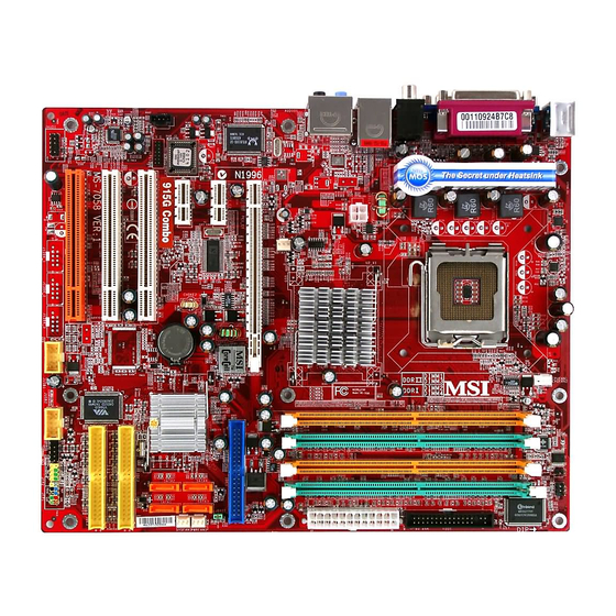
Page 18: Mainboard Layout
Chapter 2 2.1 Mainboard Layout JCI1 JL P C 1 C OM 2 T: mouse B: keyboard L G A7 7 5 C P U S o ck et Winbond W83627THF AT X_12V 91 5 G /9 1 5 GL RTL8100C Line-In Line-Out... -
Page 19: Cpu
CPU, make sure to install the cooler to prevent overheating. If you do not have the CPU cooler, contact your dealer to purchase and install them before turning on the computer. MSI Reminds You... Overheating Overheating will seriously damage the CPU and system, always make sure the cooling fan can work properly to protect the CPU from overheating. -
Page 20: Cpu & Cooler Installation
(if any). Please note not to to the center, as the arrows shown. touch the pins. MSI Reminds You... 1. Confirm if your CPU cooler is firmly installed before turning on your system. 2. Do not touch the CPU socket pins to avoid damaging. - Page 21 Introducing Mainboard 5. The CPU socket has a plastic cap on 6. Remove the cap from lever it to protect the contact from damage. h in g e s i d e ( as t h e ar row Before you have installed the CPU, shows).
- Page 22 CPU, align the 4 points (see Point 8 for details) again and push the clip to lift up the CPU. MSI Reminds You... 1. Check the information in PC Health Status of H/W Monitor in BIOS (Chapter 4) for the CPU temperature.
-
Page 23: Memory
DDR400 DDR SDRAM, and supports the memory size up to 2GB without ECC. To operate properly, at least one DIMM module must be installed. (For the updated supporting memory modules, please visit http://www. msi.com.tw/program/products/mainboard/mbd/pro_mbd_trp_list.php ) DDR DIMM Slots (DIMM 1~2) -
Page 24: Ddr Module Combination
The plastic clip at each side of the DIMM slot will automatically close. Volt Notch MSI Reminds You... You can barely see the golden finger if the module is prop- erly inserted in the socket. -
Page 25: Power Supply
Introducing Mainboard 2.4 Power Supply ATX 24-Pin Power Connector: ATX This connector allows you to connect an ATX 24-pin power supply. To connect the ATX 24-pin power supply, make pin 13 sure the plug of the power supply is inserted in the proper orientation and the pins are aligned. -
Page 26: Front Panel
Chapter 2 2.5 Front Panel Mic-in USB Ports Line-out Audio Ports These audio ports allow you to connect front audio devices. Line-out MIC-in USB Ports The mainboard provides a UHCI (Universal Host Controller Interface) Universal Serial Bus root for attaching USB devices such as keyboard, mouse or other USB-compatible devices. -
Page 27: Rear Panel
Introducing Mainboard 2.6 Rear Panel The Rear Panel provides the following connectors: Line-out Line-in Parallel Port LAN Jack Mouse Keyboard MIC -in Serial Port VGA Port USB Ports Mouse/Keyboard Connectors ® The mainboard provides two standard PS/2 mini DIN connectors ®... -
Page 28: Audio Ports
Chapter 2 Audio Ports Line Out is a connector for Speakers or Headphone. Line In is used for external CD player, Tape player, or other audio devices. MIC is a connector for stereo microphone. Line In Line Out MIC-in VGA Port The mainboard provides one DB 15-pin female connector to con- nect a VGA monitor. -
Page 29: Lan Jack
Introducing Mainboard RJ-45 LAN Jack The mainboard provides one standard RJ-45 jack for connection to Local Area Network (LAN). You can connect a network cable to the LAN jack.This LAN enables data to be transferred at 100 or 10Mbps. 10/100Mbps LAN Jack Pin Definition SIGNAL DESCRIPTION Transmit Differential Pair... -
Page 30: Parallel Port
Chapter 2 Parallel Port The mainboard provides a 25-pin female centronic connector as LPT. A parallel port is a standard printer port that supports Enhanced Parallel Port (EPP) and Extended Capabilities Parallel Port (ECP) mode. Pin Definition SIGNAL DESCRIPTION STROBE Strobe DATA0 Data0... -
Page 31: Serial Port
Introducing Mainboard Serial Port The mainboard offers one 9-pin male DIN connector as serial port. The port is 16550A high speed communication port that send/receive 16 bytes FIFOs. You can attach a serial mouse or other serial devices di- rectly to the connector. Serial Port Pin Definition 1 2 3 4 5 SIGNAL... -
Page 32: Connectors
Chapter 2 2.7 Connectors IDE Connector: IDE1 The mainboard has a 32-bit Enhanced PCI IDE and Ultra DMA 33/ 66/100 controller that provides PIO mode 0~4, Bus Master, and Ultra DMA/33/66/100 function. The connectors on the mainboard allows you to connect to the IDE devices: HDD & CD-ROM. IDE1 Floppy Disk Drive Connector: FDD The mainboard provides a standard floppy disk drive connector... -
Page 33: Serial Ata Connectors: Sata1~ Sata4
Introducing Mainboard Serial ATA Connectors: SATA1~ SATA4 The southbridge of this mainboard is ICH6 which supports four serial connectors SATA1~SATA4. SATA1~SATA4 are dual high-speed Serial ATA interface ports. Each supports 1 generation serial ATA data rates of 150 MB/s. The connectors are fully compliant with Serial ATA 1.0 specifications. -
Page 34: Front Panel Connector: Jfp1
Chapter 2 Front Panel Connector: JFP1 The mainboard provides one front panel connector for you to connect to the front panel switches and LEDs. JFP1 is compliant with ® Intel Front Panel I/O Connectivity Design Guide. Reset Power Switch Switch Power JFP1 JFP1 Pin Definition... -
Page 35: Fan Power Connectors: Cpu_Fan/Sys_Fan
Sensor +4.5V~+12V +8.5V~+12V 3.3V (High) SYS_ FAN CPU_ FAN MSI Reminds You... 1. Always consult the vendors for proper CPU cooling fan. ® 2. Please refer to the recommended CPU fans at Intel official web- site. Serial Port Connector: JCOM2 The mainboard offers one serial port JCOM2. -
Page 36: Front Usb Connectors: F_Usb1/F_Usb2
USB0+ USB1+ Key (no pin) USBOC MSI Reminds You... Note that the pins of VCC and GND must be connected cor- rectly or it may cause some damage. Chassis Intrusion Switch Connector: JCI1 This connector is connected to a 2-pin chassis switch. If the chas- sis is opened, the switch will be short. -
Page 37: Jumper
CLR_CMOS Clear Data Keep Data MSI Reminds You... You can clear CMOS by shorting 2-3 pin while the system is off. Then return to 1-2 pin position. Avoid clearing the CMOS while the system is on; it will damage the mainboard. -
Page 38: Slot
Chapter 2 2.9 Slot PCI (Peripheral Component Interconnect) Slots The PCI slots allow you to insert the expansion cards to meet your needs. When adding or removing expansion cards, make sure that you unplug the power supply first. Meanwhile, read the documentation for the expansion card to make any necessary hardware or software settings for the expansion card, such as jumpers, switches or BIOS configuration. -
Page 39: Pci Express Slot
Introducing Mainboard PCI Express Slot The PCI Express slots, as a high-bandwidth, low pin count, serial, interconnect technology, support Intel highest performance desktop plat- forms utilizing the Intel Pentium 4 processor with HT Technology with these platform benefits. You can insert the expansion cards to meet your needs. -
Page 40: Chapter 3. System Assembly
System Assembly System Assembly This chapter provides you with the installation procedures of Midas barebone. It is useful for you to read the information of mainboard setup before assembling the whole system. -
Page 41: Overview
Chapter 3 3.1 Overview The built-in MS-7036 mainboard is designed for Midas barebone only. Except MS-7036 mainboard, the built-in components of the barebone include power supply. In this chapter we’ll show you how to install CPU, F DD, HDD, Optical Drive and CPU Cooler. Installation Tools Gloves Screw Driver... -
Page 42: Checking The Items
System Assembly Checking the Items Before assembling your system, please check the items listed below for basic system operation. CPU (Optional) CPU Cooler (Optional) Optical Drive (Optional) IDE or SATA HDD (Optional) Note: The length m ust be under 190mm to avoid hindering the CPU cooler Rubber Foot (Optional) DDR SDRAM (Optional) -
Page 43: Installation Procedures
Chapter 3 3.2 Installation Procedures 1. Removing Cover, Installing Memory Modules Push the lock brackets inwards to unlock the chassis cover. Remove the chassis cover. Locate the DIMM slots. Insert the DIMM vertically into the slot. Note: The DIMM has only one notch on the center of module. -
Page 44: Installing Cpu
System Assembly 2. Installing CPU Locate the CPU socket. Pull the lever away from the socket and raise it up, then lift up the cover. Align the two pin 1 indicators (the triangles on the CPU & the CPU Clip), and use the CPU Clip to clip the CPU up, pressing the clips on both sides to the center, as the arrows shown. -
Page 45: Installing Cpu Cooler
CPU socket and secure the four to fix screws. Note: The standard CPU cooler is included with the Intel CPU, not provided by MSI. Installing the optional CPU fan Lock the screws according to the order in the right picture. MSI Reminds You... -
Page 46: Removing Drive Cage
System Assembly Lock the Fan Duct with 4 screws. Follow the direction as right picture to match the ventilation hole on the case. Rounded Side 4. Removing Drive Cage Use a screw driver to unscrew the drive cage. Pull the drive cage to release it from the chassis. -
Page 47: Installing Hdd
Chapter 3 5. Installing HDD Press the HDD lever to the left to release the HDD cage. Pull the HDD tray forwards to remove it from the drive cage. Put the HDD in the HDD tray and use 4 screws to fix it on both sides. -
Page 48: Installing Fdd And Optical Drive
System Assembly 6. Installing FDD and Optical Drive Press the F DD tray lever to release the F DD lock and push the FDD inwards to fix it. Note: The FDD tray can install the optional card reader instead. Use 2 screws to secure the F DD in the F DD tray. - Page 49 Chapter 3 Connect the cables and the power cords to the HDD and the optical drive. Note: If you are using a Serial ATA HDD, please connect it to the SATA cable. Connect the cable and the power cord to the F DD. Slide the drive cage back into the chassis.
-
Page 50: Restoring Chassis Cover
System Assembly 7. Restoring Chassis Cover Restore the chassis cover. Push the lock brackets outwards to lock the chassis cover. Attach the rubber foots to the under side (horizontal type). Horizontal type (Bottom View) Put the PC on the four foots or lay Tower type on the rubber foots. -
Page 51: Chapter 4. Bios Setup
Bios Setup BIOS Setup This chapter provides information on the BIOS Setup program and allows you to configure the system for optimum use. You may need to run the Setup program when: An error message appears on the screen during the system m booting up, and requests you to run SETUP. -
Page 52: Entering Setup
Chapter 4 Entering Setup Power on the computer and the system will start POST (Power On Self Test) process. W hen the message below appears on the screen, press <DEL> key to enter Setup. Press DEL to enter SETUP If the message disappears before you respond and you still wish to enter Setup, restart the system by turning it OFF and On or pressing the RESET button. -
Page 53: Getting Help
<F1>. The Help screen lists the appropriate keys to use and the possible selections for the highlighted item. Press <Esc> to exit the Help screen. MSI Reminds You... The items under each BIOS category described in this chapter are under continuous update for better system performance. Therefore, the description may be slightly different from the latest BIOS and should be held for reference only. -
Page 54: The Main Menu
Chapter 4 The Main Menu ® Once you enter Award BIOS CMOS Setup Utility, the Main Menu (figure below) will appear on the screen. The Main Menu allows you to select from twelve setup functions and two exit choices. Use arrow keys to select among the items and press <Enter> to accept or enter the sub-menu. - Page 55 Bios Setup Load Fail-Safe Defaults Use this menu to load the BIOS values for the best system performance, but the system stability may be affected. Load Optimized Defaults Use this menu to load factory default settings into the BIOS for stable system perfor- mance operations.
-
Page 56: Standard Cmos Features
Chapter 4 Standard CMOS Features The items in Standard CMOS Features Menu are divided into 11 categories. Each category includes no, one or more than one setup items. Use the arrow keys to highlight the item and then use the <PgUp> or <PgDn> keys to select the value you want in each item. - Page 57 Bios Setup If you select [Manual], related information is asked to be entered to the following items. Enter the information directly from the keyboard. This information should be provided in the documentation from your hard disk vendor or the system manufacturer. Access M ode The settings are CHS, LBA, Large, Auto.
-
Page 58: Advanced Bios Features
Chapter 4 Advanced BIOS Features CPU Feature Press <Enter> and the following sub-menu appears: Delay Prior to Thermal W hen the CPU temperature reaches a factory preset level, a thermal monitoring mechanism will be enabled following the appropriate timing delay specified in this field. - Page 59 In this way, the system performance is highly improved. If you disable the function, the processor will use only one core to execute the instructions. Settings: [Enabled], [Disabled]. MSI Reminds You... Enabling the functionality of Hyper-Threading Technology for your com- puter system requires ALL of the following platform Components: ®...
- Page 60 These items allow you to set the sequence of boot devices where BIOS attempts to load the operating system. MSI Reminds You... Available settings for “1st/2nd/3rd Boot Device” vary depending on the bootable devices you have installed. For example, if you did not install a floppy drive, the setting “Floppy”...
-
Page 61: Advanced Chipset Features
Bios Setup Advanced Chipset Features DRAM Timing Selectable This field allows you to select the DRAM timing setting. Setting to [By SPD] enables Max Memclock (Mhz) automatically to be determined by SPD. Selecting [Manual] allows users to configure these fields manually. Setting options: [By SPD] , [Manual]. CAS Latency Time W hen the DRAM Timing Control is set to [Manual], this field is adjustable. - Page 62 Chapter 4 Precharge Delay (tRAS) The field specifies the idle cycles before precharging an idle bank. Settings: [Auto], [4] ~ [15] (clocks). Adjust DDR Frequency W hen it is set to [Manual] in High Performance Mode, user can place an artificial memory clock limit on the system.
- Page 63 Bios Setup FIXED M emory Size Specify the size of system memory to allocate for video memory, Settings: [0M], [32M], [64MB], [128MB]. DVM T M emory Size Specify the size of DVMT memory to allocate for video memory, Settings: [0M], [32M], [64MB], [128MB], [224M].
-
Page 64: Integrated Peripherals
Chapter 4 Integrated Peripherals USB Controller This setting disables/enables the onchip USB controller. Setting options: [Enabled], [Disabled]. USB 2.0 Controller Set to [Enabled] if you need to use any USB 2.0 device in the operating system that does not support or have any USB 2.0 driver installed, such as DOS and SCO Unix. Setting options: [Enabled], [Disabled]. - Page 65 Bios Setup IO Devices Configuration Press <Enter> and the following sub-menu appears: POWER ON Function This controls how the PS/2 mouse or keyboard can power on the system. Settings: [Password], [Hot KEY], [Mouse Left], [Mouse Left], [Mouse Right], [any KEY], [BUTTON ONLY], [Keyboard 98].
- Page 66 Chapter 4 RxD, TxD Active This setting controls the receiving and transmitting speed of the IR peripheral in use. Setting options: [Hi,Hi], [Hi,Lo], [Lo,Hi], [Lo,Lo]. IR Transmission Delay This setting determines whether the IR transmission rate will be delayed while converting to receiving mode.
- Page 67 Bios Setup IDE Devices Configuration Press <Enter> and the following sub-menu appears: PCI IDE BusM aster Set this option to [Enabled] to specify that the IDE controller on the PCI local bus has bus mastering capability. Settings options: [Disabled], [Enabled]. On-Chip Primary PCI IDE The integrated peripheral controller contains two IDE interface with support for four IDE channels.
- Page 68 Chapter 4 able to see the IDE Device status listed in Standard COMS Features. [Combined] PATA and SATA will be combined. Max. of 2 IDE drives in each channel are available. [Enhanced Mode] PATA and SATA will both be enabled. Max. of 6 IDE drives are supported.
-
Page 69: Power Management Setup
Bios Setup Power Management Setup ACPI Standby State This item specifies the power saving modes for ACPI function. If your operating system supports ACPI, such as W indows 98SE, W indows ME and W indows 2000, you can choose to enter the Standby mode in S1 (POS) or S3 (STR) fashion through the setting of this field. - Page 70 Chapter 4 button. [Suspend] W hen you press the power button, the computer enters the suspend/sleep mode, but if the button is pressed for more than four seconds, the computer is turned off. Wakeup Event Setup Press <Enter> and the following sub-menu appears: Resume by PCI Device (PME#) This controls how and whether the system can be powered on by the devices installed on PCI slots.
-
Page 71: Pnp/Pci Configurations
Bios Setup PNP/PCI Configurations This section describes configuring the PCI bus system and PnP (Plug & Play) feature. PCI, or Peripheral Component Interconnect, is a system which allows I/O devices to operate at speeds nearing the speed the CPU itself uses when communicating with its special components. -
Page 72: H/W Monitor
Chapter 4 H/W Monitor This section shows the status of your CPU, fan, overall system status, etc. Monitor function is available only if there is hardware monitoring mechanism onboard. Chassis Intrusion Detect The field enables or disables the feature of recording the chassis intrusion status and issuing a warning message if the chassis is once opened. -
Page 73: Frequency/Voltage Control
Bios Setup Frequency/Voltage Control Use this menu to specify your settings for frequency/voltage control. Current CPU Clock The item shows the current status of CPU Frequency. Adjust CPU Ratio End users can overclock the processor (only if the processor supports so) by speci- fying the CPU ratio (clock multiplier) in this field. -
Page 74: Load Fail-Safe/Optimized Defaults
Chapter 4 Load Fail-Safe/Optimized Defaults The two options on the main menu allow users to restore all of the BIOS settings to the default Fail-Safe or Optimized values. The Optimized Defaults are the default values set by the mainboard manufacturer specifically for optimal performance of the mainboard. The Fail-Safe Defaults are the default values set by the BIOS vendor for stable system performance. -
Page 75: Set Password
Bios Setup Set Password W hen you select this function, a message as below will appear on the screen: Type the password, up to eight characters in length, and press <Enter>. The password typed now will replace any previously set password from CMOS memory. You will be prompted to confirm the password.
Need help?
Do you have a question about the 915 and is the answer not in the manual?
Questions and answers