Table of Contents
Advertisement
Quick Links
Advertisement
Table of Contents

Related Manuals for MSI Hetis 915


Summary of Contents for MSI Hetis 915
- Page 1 Hetis 900 Series MS-6439 (V1.X) Barebone G52-64391X1...
- Page 2 FCC-B Radio Frequency Interference Statement This equipment has been tested and found to comply with the limits for a class B digital device, pursuant to part 15 of the FCC rules. These limits are designed to provide reasonable protection against harmful interference in a residential installation.
-
Page 3: Revision History
Trademarks All trademarks are the properties of their respective owners. Intel and Pentium are registered trademarks of Intel Corporation. ® ® PS/2 and OS /2 are registered trademarks of International Business Machines ® Corporation. W indows 95/98/2000/NT/XP are registered trademarks of Microsoft Corporation. ®... -
Page 4: Safety Instructions
Safety Instructions Always read the safety instructions carefully. Keep this User’s Manual for future reference. Keep this equipment away from humidity. Lay this equipment on a reliable flat surface before setting it up. The openings on the enclosure are for air convection hence protects the equipment from overheating. - Page 5 Warning: 1. For every changes in powercord’s usage, please use an approved power cord with condition greater or equal to H05VV-F,3G , 0.75mm 2. Internal part is hazardous moving parts, please keep fingers and other body parts away. 3. For pluggable equipment, the socket-outlet shall be installed near the equipment and shall be easily accessible.
- Page 6 WEEE Statement...
- Page 8 viii...
-
Page 9: Table Of Contents
CONTENTS Chapter 1. Getting Started..................1-1 Mainboard Specifications................1-2 System Configuration..................1-4 Thermal Solution....................1-7 Chapter 2. Hardware Setup..................2-1 Mainboard Layout..................2-2 CPU (Central Processing Unit)..............2-3 Memory......................2-4 Power Supply....................2-5 Front Panel....................2-6 Back Panel.....................2-7 Connectors....................2-9 Jumper......................2-12 Slot........................2-13 Chapter 3. System Assembly................3-1 Overview.....................3-2 Installation Tools..................3-2 Installation Screws................3-2 Checking the Items................3-3 Installation Procedures.................3-4 Removing Chassis Cover..............3-4... - Page 10 Integrated Peripherals.................4-15 Power Management Setup.................4-19 PnP / PCI Configurations................4-22 PC Health Status..................4-24 Frequency / Voltage Control..............4-25 Load Fail-Safe / Optimized Defaults............4-27 Set Supervisor / User Password..............4-28 Appendix A. Realtek ALC888 Audio ..............A-1 Installing the Realtek HD Audio Driver ..............A-2 Installation for W indows 2000/XP ...............
-
Page 11: Chapter 1 Getting Started
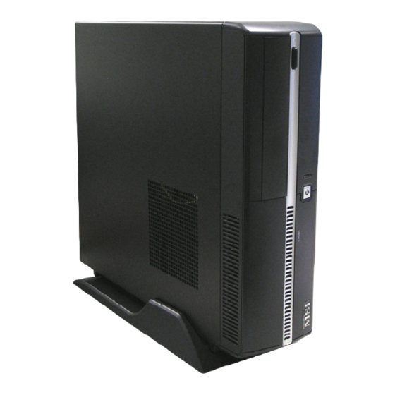
Chapter 1 Getting Started Congratulations for purchasing Hetis 900 Series (MS-6439) Barebone. Hetis 900 Series Barebone is your best Slim PC choice. W ith the fantastic appearance and small form factor, it can easily be set anywhere. The feature packed platform also gives you an exciting PC experience. -
Page 12: Mainboard Specifications
® - Supports Intel Presler LGA775 Pentium D up to 960 (3.6GHz) ® ® (For the latest information about CPU, please visit http://www.msi. com.tw/program/products/slim_pc/slm/pro_slm_cpu_support.php) Supported FSB - 400 / 533 / 800 / 1066 MHz Chipset - North Bridge: VIA P4M900 Chipset ®... - Page 13 Getting Started Connectors Back Panel - 1 PS/2 Mouse Port - 1 PS/2 Keyboard Port - 2 COM Ports - 1 VGA Port - 1 DVI Port - 6 Audio Jacks - 1 LAN Jack (RJ45) - 4 USB 2.0 Ports Front Panel - 2 Audio Jacks (Headphone and Microphone) - 2 USB 2.0 Ports...
-
Page 14: System Configuration
M S-6439 Barebone System Configuration Front View 1. Headphone (Green) 5. HDD LED 2. M icrophone (Pink) 6. ODD Eject / Close Button 3. USB 2.0 Ports 7. Optical Disk Drive (Optional) 4. Power Button / Power LED 8. Card Reader Drive (Optional) -
Page 15: Back View
Getting Started Back View 1. Voltage Selector 8. DVI Port 2. Power Jack 9. VGA Port 3. Ventilation Hole 10. Audio Jacks 4. USB 2.0 Ports 11. Power Switch 5. PS/2 M ouse (Green) 12. Support Bracket Spring 6. PS/2 Keyboard (Purple) 13. -
Page 16: Chassis Design
M S-6439 Barebone Chassis Design † Dimension: 330MM (D) x 320MM (W) x 94MM (H) † Minimized screw structure † Detachable bay housing † Multiple ventilation holes Back Side Bottom 1. CPU Fan Ventilation Hole 5. System Ventilation Hole 2. System Ventilation Hole 6. -
Page 17: Thermal Solution
Getting Started Thermal Solution To prevent the system from overheating, we have adopted a specially designed CPU cooler and multiple ventilation holes for better cooling effects. The specially designed CPU cooler supports Intel LGA775 - Conroe Core 2 Duo and Presler Pentium ®... -
Page 18: System Design
M S-6439 Barebone System Design Back Panel Power Supply Sy st em Po w e r Supply Fan Socket M e mo r y Front Panel Driver Bays DIMM Slots (from top to bottom) Card Reader Drive Optical Disk Drive Hard Disk Drive... -
Page 19: System Air Flow Direction
Getting Started System Air Flow Direction Back Panel Power Supply Sy st em Po w e r Supply Fan Socket M e mo r y Front Panel Driver Bays DIMM Slots (from top to bottom) Card Reader Drive Optical Disk Drive Hard Disk Drive After the installation is completed, please keep other objects away from the ventilation hole at least 2.5cm... -
Page 20: Chapter 2 Hardware Setup
Chapter 2 Hardware Setup This chapter provides you with the information about hard- ware setup procedures. W hile doing the installation, be careful in holding the components and follow the installation procedures. For some components, if you install in the wrong orientation, the components will not work properly. -
Page 21: Mainboard Layout
M S-6439 Barebone Mainboard Layout BIOS SATA2 SATA1 JCD1 Codec LAN Chip VT 8237A IDE1 SYS_F2 ATX1 P4M900 BATT JBAT1 CPU_F1 JFP1 JPW1 CASE_OPEN1 JACK3 JACK2 USB2 USB1 MS-7331 (V1.X) Mainboard... -
Page 22: Cpu (Central Processing Unit)
If you do not have the CPU cooler, contact your dealer to purchase and install them before turning on the computer. (For the latest information about CPU, please visit: http://www.msi.com.tw/program/products/slim_pc/slm/pro_slm_cpu_support.php) Important Overheating... -
Page 23: Memory
M S-6439 Barebone Memory These DIMM slots are used for installing memory modules. (For more information on compatible components, please visit: http://www.msi.com.tw/program/products/mainboard/mbd/pro_mbd_trp_list.php) DIMM1~2 240-pin, 1.8V 64 x 2 = 128-pin 56 x 2 = 112-pin Important Each DIMM slot supports up to a maximum size of 1GB. -
Page 24: Power Supply
Hardware Setup Power Supply ATX 20-Pin Power Connector: ATX1 This connector allows you to connect to an power supply. To connect to the power supply, make sure the plug of the power supply is inserted in the proper orientation and the pins are aligned. Then push down the power supply firmly into the connector. Pin Definition SIGNAL SIGNAL... -
Page 25: Front Panel
M S-6439 Barebone Front Panel The Front Panel provides the following connectors: Headphone M icrophone USB Ports (G reen) (Pink) Audio Ports These audio ports allow you to connect front audio devices. USB Ports The mainboard provides a UHCI (Universal Host Controller Interface) Universal Serial Bus root for attaching USB devices such as keyboard, mouse or other USB-compat- ible devices. -
Page 26: Back Panel
Hardware Setup Back Panel The Rear Panel provides the following connectors: M o us e VGA Port Line-In RS-Out Line-Out CS-Out SS-Out USB Ports Keyboard Serial Ports DVI Port The standard RJ-45 LAN jack is for connection to the Local Area Network (LAN). You can connect a network cable to it. - Page 27 M S-6439 Barebone Serial Port The serial port is a 16550A high speed communications port that sends/ receives 16 bytes FIFOs. You can attach a serial mouse or other serial devices directly to the connector. VGA Port The DB15-pin female connector is provided for monitor. DVI Port The DVI (Digital Visual Interface) connector allows you to connect a LCD monitor.
-
Page 28: Connectors
Hardware Setup Connectors IDE Connector: IDE1 This connector supports IDE hard disk drives, optical disk drives and other IDE devices. IDE1 Important If you install two IDE devices on the same cable, you must configure the drives separately to Master / Slave mode by setting jumpers. Refer to IDE device’s documentation supplied by the vendors for jumper setting instructions. - Page 29 M S-6439 Barebone Serial ATA Connectors: SATA1 / SATA2 These connectors are high-speed Serial ATA interface port. Each connector can connect to one Serial ATA device. SATA1 / SATA2 Fan Power Connectors: CPU_F1 / SYS_F2 The CPU_F1 (processor fan) and SYS_F2 (system fan) support system cooling fan with +12V.
- Page 30 Hardware Setup Front Panel Connector: JFP1 This connector is for electrical connection to the front panel switches and LEDs. The JFP1 is compliant with Intel Front Panel I/O Connectivity Design Guide. ® Pin Definition DESCRIPTION SIGNAL Hard disk LED pull-up HD_LED_P 10 9 MSG LED pull-up...
-
Page 31: Jumper
M S-6439 Barebone Jumper Clear CMOS Jumper: JBAT1 There is a CMOS RAM onboard that has a power supply from an external battery to keep the data of system configuration. W ith the CMOS RAM, the system can auto- matically boot OS every time it is turned on. If you want to clear the system configuration, set the jumper to clear data. -
Page 32: Slot
Hardware Setup Slot PCI Express Slot: SLOT1 (For Riser Card Use Only) The mainboard provides one PCI-X express slot. The PCI-X slot allows you to insert Riser Cards and the Riser Cards are included in the barebone. The Riser Cards allows you to insert PCI/PCI-E expansion card. -
Page 33: Chapter 3. System Assembly
System Assembly Chapter 3 System Assembly This chapter provides you with the information about sys- tem assembly procedures. W hile doing the installation, be careful in holding the components and follow the installa- tion procedures. Use a grounded wrist strap before handling computer components. -
Page 34: Overview
M S-6439 Barebone Overview The built-in mainboard is designed for Hetis 900 Series Barebone only. Except the mainboard, the built-in components of the barebone include power supply. In this chapter we will show you how to install CPU, CPU Cooler, Memory Modules, Card Reader, Hard Disk Drive (HDD) and Optical Disk Drive (ODD). -
Page 35: Checking The Items
System Assembly Checking the Items Before assembling your system, please check the items listed below for basic sys- tem operation. The footstand and the CPU cooler are included in the package, other items are optional. Footstand CPU Cooler CPU (Optional) ODD (Optional) HDD (Optional) Memory M odule (Optional) -
Page 36: Installation Procedures
M S-6439 Barebone Installation Procedures 1. Removing Chassis Cover Unlock the two sc rews on the back panel with hands. Remove the chassis cover. Press the level on the support bracket spring to release it. Unlock the screw on the front panel to release the drive cage. -
Page 37: Installing Hard Disk Drive (Hdd)
System Assembly 2. Installing Hard Disk Drive (HDD) Lift the drive cage to slide aside. Pull the HDD tray forwards to remove it from the chassis. Put the HDD in the HDD tray and use four screws to fix it on both sides. Connect the cable and the power cord to the HDD, then put the HDD tray back to secure it on the drive cage. -
Page 38: Installing Optical Disk Drive (Odd)
M S-6439 Barebone 3. Installing Optical Disk Drive (ODD) Pull the lock brackets outwards on the both sides to release. Insert the ODD and push the lock brack- ets back to fix it. Connect the cable and the power cord to the ODD, then restore the drive cage. -
Page 39: Installing Card Reader (Optional)
System Assembly 4. Installing Card Reader (Optional) Use the screwdriver to unlock the card reader cage. Insert the card reader into the cage with 15 degree angle. Insert the LED into the cage and lock the card reader with two screws. Restore the card reader back and con- nect the cable to the CR1 connector on the mainboard. -
Page 40: Installing Memory Modules
M S-6439 Barebone 5. Installing Memory Modules Locate the DIMM slots. Insert the DIMM vertically into the slot. Note: The DIMM has only one notch on the center of module. It will only fit in the right direction. -
Page 41: Installing Cpu
System Assembly 6. Installing CPU Locate the CPU socket. Pull the lever away from the socket and raise it up, then lift up the cover. Put the CPU onto the socket. Note: Make sure the pins are com- pletely embedded into the socket. The C P U c a n o n ly f it in t h e c o r re c t direction. -
Page 42: Installing Cpu Cooler
M S-6439 Barebone 7. Installing CPU Cooler Place the CPU cooler onto the CPU socket and secure the four screws. Important Do not fix any screw until all the four screws are in the position, and lock the four screws with balance, or it may shift the CPU position to cause the system unbootable. -
Page 43: Restoring Chassis Cover
System Assembly 8. Restoring Chassis Cover Restore the support bracket. Restore the chassis cover. L oc k th e c h as s i s c over wit h th e s c rews . Tower ty pe Horizontal type 3-11... -
Page 44: Installing Footstand
M S-6439 Barebone 9. Installing Footstand Lift up the PC and put the rubber feet into the pits on the footstand. Make sure the rubber feet to get stuck on the footstand. Put the PC on the footstand or lay on the rubber foots. -
Page 45: Chapter 4. Bios Setup
BIOS Setup Chapter 4 BIOS Setup This chapter provides information on the BIOS Setup pro- gram and allows you to configure the system for optimum use. You may need to run the Setup program when: An error message appears on the screen during the system booting up, and requests you to run SETUP. -
Page 46: Entering Setup
M S-6439 Barebone Entering Setup Power on the computer and the system will start POST (Power On Self Test) process. W hen the message below appears on the screen, press <DEL> key to enter Setup. Press DEL to enter SETUP If the message disappears before you respond and you still wish to enter Setup, restart the system by turning it OFF and On or pressing the RESET button. -
Page 47: Control Keys
BIOS Setup Control Keys < > Move to the previous item < > Move to the next item < > Move to the item in the left hand < > Move to the item in the right hand <Enter> Select the item <Esc>... -
Page 48: The Main Menu
M S-6439 Barebone The Main Menu Standard CM OS Features Use this menu for basic system configurations, such as time, date etc. Advanced BIOS Features Use this menu to setup the items of the special enhanced features. Advanced Chipset Features Use this menu to change the values in the chipset registers and optimize your system’s performance. - Page 49 BIOS Setup PC Health Status This entry shows your PC health status. Frequency / Voltage Control Use this menu to specify your settings for frequency / voltage control. Load Fail-Safe Defaults Use this menu to load the default values set by the BIOS vendor for stable system performance.
-
Page 50: Standard Cmos Features
M S-6439 Barebone Standard CMOS Features Date (mm:dd:yy) This allows you to set the system to the date that you want (usually the current date). The format is <day> <month> <date> <year>. Day of the week, from Sun to Sat, determined by BIOS. Read only. month The month from Jan. - Page 51 BIOS Setup IDE HDD Auto-Detection Press Enter to allow BIOS to auto-detect the type of the HDDs. IDE Channel 0 M aster Press PgUp/<+> or PgDn/<-> to select Manual, None or Auto type. Note that the specifications of your drive must match with the drive table. The hard disk will not work properly if you enter improper information for this category.
-
Page 52: Advanced Bios Features
M S-6439 Barebone Advanced BIOS Features CPU Feature Press <Enter> and the following sub-menu appears: Delay Prior to Thermal W hen the CPU temperature reaches a factory preset level, a thermal monitor- ing mechanism will be enabled following the appropriate timing delay specified in this field. - Page 53 BIOS Setup Limit CPUID MaxVal The item allows you to enable and disable the CPU ID maximum value. [Enabled] Set to [Enabled] only when you have Prescott CPU and NT4.0 operating system. [Disabled] Set to [Disabled] if you have operating system other than NT4.0.
- Page 54 M S-6439 Barebone Virus Warning The item is to set the Virus W arning feature for IDE Hard Disk boot sector protection. If the function is enabled and any attempt to write data into this area is made, BIOS will display a warning message on screen and beep. Important Many disk diagnostic programs that access the boot sector table can trigger the virus warning message.
- Page 55 BIOS Setup Security Option This specifies the type of BIOS password protection that is implemented. Settings are described below: Option Descripion [Setup] The password prompt appears only when end users try to run Setup. [System] A password prompt appears every time when the computer is powered on or when end users try to run Setup.
-
Page 56: Advanced Chipset Features
M S-6439 Barebone Advanced Chipset Features DRAM Clock / Drive Control Press <Enter> and the following sub-menu appears: Current FSB / DRAM Frequency Those two items are read-only to show the current FSB and DRAM Frequency information. DRAM Clock Use this field to configure the clock frequency of the installed DRAM. 4-12... - Page 57 BIOS Setup Important The value plus a ratio (CPU: DDR) with parentheses means the non-synchronous overclocking. DRAM Timing The value in this field depends on performance parameters of the installed memory chips (DRAM). Do not change the value from the factory setting un- less you install new memory that has a different performance rating than the original DRAMs.
- Page 58 M S-6439 Barebone Select Display Device Use the field to select the type of device you want to use as the display(s) of the system. CPU & PCI Bus Control Press <Enter> and the following sub-menu appears: PCI M aster 0 WS Write W hen [Enabled], writes to the PCI bus are executed with zero wait states.
-
Page 59: Integrated Peripherals
BIOS Setup Integrated Peripherals VIA OnChip IDE Device Press <Enter> and the following sub-menu appears: SATA Controller This allows you to enable or disable onchip Serial ATA controller. IDE DM A transfer access Setting to [Enabled] will open DMA bus master and execute DMA action in DOS, which will make the data transferring faster. - Page 60 M S-6439 Barebone OnChip IDE Channel0 The integrated peripheral controller contains an IDE interface with support for two IDE channels. Choose [Enabled] to activate each channel separately. IDE Prefetch M ode The onboard IDE drive interfaces support IDE prefetching, for faster drive accesses.
- Page 61 BIOS Setup Super IO Device Press <Enter> and the following sub-menu appears: Onboard Serial Port 1 / 2 Select a logical COM port name and matching address for the first and second serial ports. Select an address and corresponding interrupt for the first and second serial ports.
- Page 62 M S-6439 Barebone USB Keyboard Function Select [Enabled] if your system contains a Universal Serial Bus (USB) control- ler and you have a USB keyboard. USB M ouse Function Select [Enabled] if you need to use a USB-interfaced mouse in the operating system.
-
Page 63: Power Management Setup
BIOS Setup Power Management Setup ACPI function This item is to activate the ACPI (Advanced Configuration and Power Management Interface) Function. If your operating system is ACPI-aware, such as Windows 98SE/ 2000/ME, select [Enabled]. Important S3-related functions described in this section are available only when your BIOS supports S3 sleep mode. - Page 64 M S-6439 Barebone [S1/POS] The S1 sleep mode is a low power state. In this state, no system context is lost (CPU or chipset) and hard ware maintains all system context. [S3/STR] The S3 sleep mode is a lower power state where the information of system configuration and open appli cations/files is saved to main memory that remains powered while most other hardware components turn...
- Page 65 BIOS Setup Wakeup Event Detect Press <Enter> to enter sub-menu and the following screen appears: PS2KB Wakeup Key select The item specifies how the system will be awakened from power saving mode when input signal of the keyboard is detected. PowerOn by PCI Card This controls how and whether the system can be powered on by the devices installed on PCI slots.
-
Page 66: Pnp / Pci Configurations
M S-6439 Barebone PnP / PCI Configurations Reset Configuration Data The ESCD (Extended System Configuration Data) NVRAM (Non-volatile Random Ac- cess Memory) is where the BIOS stores resource information for both PNP and non- PNP devices in a bit string format. W hen the item is set to [Enabled], the system will reset ESCD NVRAM right after the system is booted up and then set the setting of the item back to [Disabled] automatically. - Page 67 BIOS Setup IRQ Resources The items are adjustable only when Resources Controlled By is set to Manual. Press <Enter> and you will enter the sub-menu of the items. IRQ Resources list IRQ 3/4/5/7/ 9/10/11/12/14/15 for users to set each IRQ a type depending on the type of device using the IRQ.
-
Page 68: Pc Health Status
M S-6439 Barebone PC Health Status Current System / CPU Temperature, SYS / CPU Fan Speed, Vcore, VCC5, +12V, VCC3 (V), VBAT (V), 3VSB (V) These items display the current status of all of the monitored hardware devices/ components such as CPU voltages, temperatures and all fans’ speeds. 4-24... -
Page 69: Frequency / Voltage Control
BIOS Setup Frequency / Voltage Control CPU Clock Ratio This setting controls the multiplier that is used to determine the internal clock speed of the processor relative to the external or motherboard clock speed. Auto Detect PCI Clk This item is used to auto detect the PCI slots. W hen set to [Enabled], the system will remove (turn off) clocks from empty PCI slots to minimize the electromagnetic inter- ference (EMI). - Page 70 M S-6439 Barebone Important 1. If you do not have any EMI problem, leave the setting at [Disabled] for optimal system stability and performance. But if you are plagued by EMI, select the value of Spread Spectrum for EMI reduction. 2.
-
Page 71: Load Fail-Safe / Optimized Defaults
BIOS Setup Load Fail-Safe / Optimized Defaults The two options on the main menu allow users to restore all of the BIOS settings to the default Fail-Safe or Optimized values. The Optimized Defaults are the default values set by the mainboard manufacturer specifically for optimal performance of the mainboard. -
Page 72: Set Supervisor / User Password
M S-6439 Barebone Set Supervisor / User Password W hen you select this function, a message as below will appear on the screen: Type the password, up to six characters in length, and press <Enter>. The password typed now will replace any previously set password from CMOS memory. You will be prompted to confirm the password. -
Page 73: Appendix A Realtek Alc888 Audio
Realtek ALC888 Audio Appendix A Realtek ALC888 Audio The Realtek ALC888 provides 10-channel DAC that si- multaneously supports 7.1 sound playback and 2 chan- nels of independent stereo sound output (multiple streaming) through the Front-Out-Left and Front-Out- Right channels. -
Page 74: Installing The Realtek Hd Audio Driver
M S-6439 Barebone Installing the Realtek HD Audio Driver You need to install the driver for Realtek ALC888 codec to function properly before you can get access to 2-, 4-, 6-, 8- channel or 7.1+2 channel audio operations. Follow the procedures described below to install the drivers for different operating systems. - Page 75 Realtek ALC888 Audio 3. Click Next to install the Realtek High Definition Audio Driver. Click here 4. Click Finish to restart the system. Select this option Click here...
-
Page 76: Software Configuration
M S-6439 Barebone Software Configuration After installing the audio driver, you are able to use the 2-, 4-, 6- or 8- channel audio feature now. Click the audio icon from the system tray at the lower-right corner of the screen to activate the HD Audio Configuration. It is also available to enable the audio driver by clicking the Realtek HD Audio M anager from the Control Panel. -
Page 77: Sound Effect
Realtek ALC888 Audio Sound Effect Here you can select a sound effect you like from the Environment list. Environment Simulation You will be able to enjoy different sound experience by pulling down the arrow, totally 23 kinds of sound effect will be shown for selection. Realtek HD Audio Sound Manager also provides five popular settings “Stone Corridor”, “Bathroom”, “Sewer pipe”, “Arena”... - Page 78 M S-6439 Barebone Equalizer Selection Equalizer frees users from default settings; users may create their owned preferred settings by utilizing this tool. 10 bands of equalizer, ranging from 100Hz to 16KHz. Save Reset The settings are saved 10 bands of equalizer permanently for future would go back to the use.
- Page 79 Realtek ALC888 Audio Frequently Used Equalizer Setting Realtek recognizes the needs that you might have. By leveraging our long experience at audio field, Realtek HD Audio Sound Manager provides you certain optimized equal- izer settings that are frequently used for your quick enjoyment. [How to Use It] Other than the buttons “Pop”...
-
Page 80: Mixer
M S-6439 Barebone Mixer In the Mixer part, you may adjust the volumes of the rear and front panels individually. 1. Adjust Volume You can adjust the volume of the speakers that you pluged in front or rear panel by select the Realtek HD Audio rear output or Realtek HD Audio front output items. - Page 81 Realtek ALC888 Audio Important You have to plug audio device into the jacks on the rear and front panel first before enable the multi-stream function. W hen you are playing the first audio source (for example: use W indows Media Player to play DVD/VCD), the output will be played from the rear panel, which is the default setting.
- Page 82 M S-6439 Barebone 3. Playback control Tool Mute Playback device This function is to let you freely decide which ports to output the sound. And this is essential when multi- streaming playback enabled. - Realtek HD Audio Rear Output - Realtek HD Audio Front Output M u te You may choose to mute single or multiple volume controls or to completely mute sound output.
- Page 83 Realtek ALC888 Audio 4. Recording control Tool Mute Recording device -Back Line in/Mic, Front Lin in -Realtek HD Audio Input M u te You may choose to mute single or multiple volume controls or to completely mute sound input. Tool - Show the following volume controls This is to let you freely decide which volume control items to be displayed.
-
Page 84: Audio I/O
M S-6439 Barebone Audio I/O In this tab, you can easily configure your multi-channel audio function and speakers. You can choose a desired multi-channel operation here. a. Headphone for the common headphone b. 2CH Speaker for Stereo-Speaker Output c. 4CH Speaker for 4-Speaker Output d. - Page 85 Realtek ALC888 Audio Connector Settings Click to access connector settings. Disable front panel jack detection (option) Find no function on front panel jacks? Please check if front jacks on your system are so-called AC’97 jacks. If so, please check this item to disable front panel jack detection. M ute rear panel output when front headphone plugged in.
- Page 86 M S-6439 Barebone Test Speakers You can select the speaker by clicking it to test its functionality. The one you select will light up and make testing sound. If any speaker fails to make sound, then check whether the cable is inserted firmly to the connector or replace the bad speakers with good ones.
-
Page 87: Microphone
Realtek ALC888 Audio Microphone In this tab you may set the function of the microphone. Select the Noise Suppres- sion to remove the possible noise during recording, or select Acoustic Echo Cancelltion to cancel the acoustic echo druing recording. Acoustic Echo Cancelltion prevents playback sound from being recorded by mi- crophone together with your sound. -
Page 88: Audio Demo
M S-6439 Barebone 3D Audio Demo In this tab you may adjust your 3D positional audio before playing 3D audio applica- tions like gaming. You may also select different environment to choose the most suitable environment you like. A-16... -
Page 89: Information
Realtek ALC888 Audio Information In this tab it provides some information about this HD Audio Configuration utility, including Audio Driver Version, DirectX Version, Audio Controller & Audio Codec. You may also select the language of this utility by choosing from the Language list. Also there is a selection Show icon in system tray. - Page 90 M S-6439 Barebone Hardware Setup Connecting the Speakers W hen you have set the Multi-Channel Audio Function mode properly in the software utility, connect your speakers to the correct phone jacks in accordance with the setting in software utility. n 2-Channel M ode for Stereo-Speaker Output Refer to the following diagram and caption for the function of each phone jack on the back panel when 2-Channel Mode is selected.
- Page 91 Realtek ALC888 Audio n 4-Channel M ode for 4-Speaker Output Back Panel 4-Channel Analog Audio Output Line-In Line-Out (Front channels) RS-Out (Rear surround channels) No function No function A-19...
- Page 92 M S-6439 Barebone n 6-Channel M ode for 6-Speaker Output Back Panel 6-Channel Analog Audio Output Line-In Line-Out (Front channels) RS-Out (Rear surround channels) CS-Out (Center and Subwoofer channel) No function A-20...
- Page 93 Realtek ALC888 Audio n 8-Channel M ode for 8-Speaker Output Back Panel 8-Channel Analog Audio Output Line-In Line-Out (Front channels) RS-Out (Rear surround channels) CS-Out (Center and Subwoofer channel) SS-Out (Side channels) A-21...
Need help?
Do you have a question about the Hetis 915 and is the answer not in the manual?
Questions and answers