Table of Contents
Advertisement
Quick Links
Advertisement
Table of Contents

Related Manuals for MSI MS6243


Summary of Contents for MSI MS6243
- Page 1 Hermes 845GV Series MS6243 Barebone Version 2.2 G52-B6243X6-K01...
- Page 2 Manual Rev: 2.2 Release Date: Dec. 2002 FCC-B Radio Frequency Interference Statement This equipment has been tested and found to comply with the limits for a class B digital device, pursuant to part 15 of the FCC rules. These limits are designed to provide reasonable protection against harmful interference when the equip- ment is operated in a commercial environment.
-
Page 3: Copyright Notice
Copyright Notice The material in this document is the intellectual property of MICRO-STAR INTERNATIONAL. We take every care in the preparation of this document, but no guarantee is given as to the correctness of its contents. Our products are under continual improvement and we reserve the right to make changes without notice. -
Page 4: Safety Instructions
Safety Instructions Always read the safety instructions carefully. Keep this User’s Manual for future reference. Keep this equipment away from humidity. Lay this equipment on a reliable flat surface before setting it up. The openings on the enclosure are for air convection hence protects the equipment from overheating. -
Page 5: About This Manual
About This Manual This manual is written based on the idea to make a brief introduction of MS6243 barebone. It is ideal for the end-users to get a complete understanding about this model. The advanced users can also get help while studying this book. -
Page 6: Technical Support
Alternatively, please try the follow- ing help resources for further guidance. Visit the MSI website for FAQ, technical guide, BIOS updates, driver updates, and other information: http://www. msi.com.tw/... -
Page 7: Table Of Contents
CONTENTS Chapter 1. Introduction ................1-1 Barebone Specifications ............... 1-2 Mainboard Specifications ..............1-4 Mainboard Layout ................1-6 Quick Component Guide ..............1-7 Chapter 2. Mainboard Setup ..............2-1 Central Processing Unit: CPU .............. 2-2 CPU Installation Procedure ............2-3 Attaching CPU Cooler .............. - Page 8 VGA Port ..................2-14 USB Ports ..................2-15 Mouse Connector ............... 2-15 Keyboard Connector ..............2-16 Connectors ..................2-17 Hard Disk Connectors: IDE1 & IDE2 ........... 2-17 Front Panel Connector: JFP1 ............2-18 CD-In Connector: JCD1 ............... 2-19 Fan Power Connectors: CPUFAN1/SYS_FAN ......2-20 FDD Connector: FDD1 ..............
- Page 9 Advanced BIOS Features ..............4-8 Advanced Chipset Features ............... 4-13 Power Management Features ............. 4-16 PNP/PCI Configurations ..............4-19 Integrated Peripherals ................ 4-22 PC Health Status ................4-25 Frequency/Voltage Control ..............4-26 Set Supervisor/User Password ............4-27 Load Optimal/Fail-Safe Defaults ............4-28 Appendix: Using 4- or 6-Channel Audio Function ........
-
Page 10: Chapter 1. Introduction
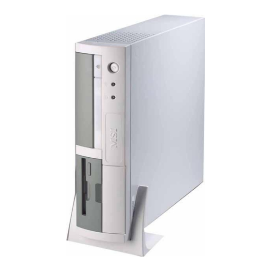
Introduction Introduction Congratulations for purchasing MS-6243 barebone. The MS- 6243 barebone is your best Slim PC choice. Based on the “all-in- one” design idea, the MS-6243 provides 2 “1394” ports (option), 6 USB ports, 2 TV-out jacks (option), 1 DVI jack (option) and 1 SPDIF jack. -
Page 11: Barebone Specifications
Chapter 1 Barebone Specifications Chassis Dimension: 310mm (H) x 84mm (W) x 345mm (D) Minimised screw structure Detachable bay housing Front Panel 1. Slim Floppy Drive 7. USB Ports 8. MIC-in 2. CD-ROM Drive 9. Line-out 3. Power Switch 10. SPDIF Jack (optical) 4. -
Page 12: Back Panel
Introduction Back Panel 1. S-Video Port (option) 10. DVI Port (option) 2. COM A 11. VGA Port 3. PCI Slots 12. RJ-45 LAN Jack 4. COM B 13. USB Ports 5. MIC-in 14. PS/2 Mouse 6. Line-in 15. PS/2 Keyboard 7. -
Page 13: Mainboard Specifications
Chapter 1 Mainboard Specifications Model: MS-6557 ® Supports Socket 478 for Intel Pentium™ 4 processor up to 2.53GHz and above Chipset ® Intel 845GV chipset - Integrated video accelerator - Supports 100/133 MHz FSB ® - Supports 533 /400 MHz Intel NetBurst micro-architecture bus - Supports DDR 200/266 memory. - Page 14 Introduction - 1 LAN (RJ45) port - 1 DVI connector for LCD monitor (Optional) - 2 TV out connectors: AV out & S-video out (Optional) - 6-pin 1394 connector (Optional) - 2 serial ports (On-board x1; Header x 1) Front Panel - 2 audio ports (Headphone-out, Mic_in) - 4 USB ports - 1 SPDIF...
-
Page 15: Mainboard Layout
Chapter 1 Mainboard Layout MS-6557 (V3.X) Mainboard... -
Page 16: Quick Component Guide
Introduction Quick Component Guide Component Function Reference Socket 478 Installing CPU See p. 2-2~2-3 DIMM1 & DIMM2 Installing DIMM modules See p. 2-5~2-6 ATX Power Supply Connecting to ATX Power Supply See p. 2-7 IDE1 & IDE2 Connecting to HDD See p. -
Page 17: Chapter 2. Mainboard Setup
Mainboard Setup Mainboard Setup This chapter provides you with the information about hard- ware setup procedures for MS-6557 mainboard. While doing the installation, be careful in holding the components and follow the installation procedures. For some components, if you install in the wrong orientation, the components will not work properly. -
Page 18: Central Processing Unit: Cpu
Chapter 2 Central Processing Unit: CPU ® The mainboard supports Intel Pentium 4 processors (Willimate 478 and Northwood 478). The mainboard uses a CPU socket called Socket 478 for easy CPU installation. While installing the CPU, make sure the CPU has a heat sink and a cooling fan attached on the top to prevent overheating. -
Page 19: Cpu Installation Procedure
Mainboard Setup CPU Installation Procedures Turn off the power and unplug the power cord before install- ing the CPU. Open Lever Pull the lever sideways away Sliding 90 degree from the socket. Make sure Plate to raise the lever up to a 90- degree angle. -
Page 20: Attaching Cpu Cooler
Chapter 2 Attaching CPU Cooler The CPU cooler included in the packing is designed specially for MS- 6243 barebone. It is different from other CPU cooler of Pentium 4. See the follows for the features: Copper Material The heatsink is made of copper that has better heat-disseminating effect. Shockproof Effect The cooler has good shockproof effect through the mechanical combi nation design of CPU fan and heatsink. -
Page 21: Memory Installation
Mainboard Setup Memory Installation The mainboard provides two sockets for 184-pin DDR SDRAM DIMM (Double In-Line Memory Module) and supports the memory size up to 2 GB. You can install PC2100/DDR266 or PC1600/DDR200 modules into the DDR DIMM slots. DDR1 DDR2 Introduction to DDR SDRAM DDR (Double Data Rate) SDRAM is similar to conventional SDRAM, but doubles the rate by transferring data twice per cycle. -
Page 22: Ddr Module Combination
Chapter 2 DDR Module Combination Install at least one DIMM module into the slots. Memory modules can be installed into the slots in any order. You can install either single or double- sided modules to meet your need. Slot Combination DDR 1 DDR 2 64MB~2GB... -
Page 23: Power Supply
Mainboard Setup Power Supply ATX 20-Pin Power Connector: ATX1 This connector allows you to connect to an ATX power supply. To connect to the ATX power supply, make sure the plug of the power supply is inserted in the proper orientation and the pins are aligned. Then push down the power supply firmly into the connector. -
Page 24: Front Panel
Chapter 2 Front Panel Audio Port J1394-2 SPDIF Jack USB Ports IEEE 1394 Port: J1394-2 The mainboard provides two IEEE 1394 ports. This smaller one is designed for you to connect the IEEE 1394 device with external power. The IEEE 1394 high- speed serial bus complements USB by providing enhanced PC connectivity for a wide range of devices, including consumer electronics audio/video (A/V) appliances, storage peripherals, other PCs, and portable devices. -
Page 25: Usb Ports
Mainboard Setup USB Ports The mainboard provides a UHCI (Universal Host Controller Interface) Universal Serial Bus root for attaching USB devices such as keyboard, mouse or other USB-compatible devices. You can plug the USB device directly into these connectors. USB Port Description SIGNAL DESCRIPTION -Data 0... -
Page 26: Back Panel
Chapter 2 Back Panel The Rear Panel provides the following connectors: COM A Parallel Port LAN Jack Mouse DVI Port Line-in MIC -in VGA Port Keyboard J1394-1 USB Ports Line-out Serial Ports: COM A & COM B The mainboard offers two 9-pin male DIN connectors as serial port COM A &... -
Page 27: Audio Port
Mainboard Setup Audio Port Line Out is a connector for Speakers or Headphones. Line In is used for external CD player, Tape player, or other audio devices. Mic-in is a connector for microphones. 1/8” Stereo Audio Connectors Line Out Line In MIC-in Note: The mainboard supports 4- or 6- channel audio function. -
Page 28: Parallel Port
Chapter 2 Parallel Port The mainboard provides a 25-pin female centronic connector as LPT. A parallel port is a standard printer port that supports Enhanced Parallel Port (EPP) and Extended Capabilities Parallel Port (ECP) mode. Pin Definition SIGNAL DESCRIPTION STROBE Strobe DATA0 Data0... -
Page 29: Dvi Port
Mainboard Setup DVI Port The mainboard provides a DVI (Digital Visual Interface) connector which allows you to connect an LCD monitor. The DVI connector provides a high-speed digital interconnection between the computer and its display device. C1 C2 DVI-I Connector P i n Signal Assignment P i n... -
Page 30: Ieee 1394 Port: J1394-1
Chapter 2 IEEE 1394 Port: J1394-1 The bigger 6-pin IEEE 1394 Port on the back panel is designed for you to connect to IEEE 1394 devices without external power. That means the mainboard can provide the power for the devices connected to this port. Software Support ®... -
Page 31: Usb Ports
Mainboard Setup USB Ports The mainboard provides a UHCI (Universal Host Controller Interface) Universal Serial Bus root for attaching USB devices such as keyboard, mouse or other USB-compatible devices. You can plug the USB device directly into the connector. USB Port Description SIGNAL DESCRIPTION -Data 0... -
Page 32: Keyboard Connector
Chapter 2 Keyboard Connector ® The mainboard provides a standard PS/2 keyboard mini DIN connec- ® ® tor for attaching a PS/2 keyboard. You can plug a PS/2 keyboard directly into this connector. Pin Definition SIGNAL DESCRIPTION Keyboard DATA Keyboard DATA No connection Ground Keyboard Clock... -
Page 33: Connectors
Mainboard Setup Connectors Hard Disk Connectors: IDE1 & IDE2 The mainboard has a 32-bit Enhanced PCI IDE and Ultra DMA 33/66/100 controller that provides PIO mode 0~4, Bus Master, and Ultra DMA/33/66/100 function. The two connectors on the motherboard allows you to connect to only two IDE devices. -
Page 34: Front Panel Connector: Jfp1
Chapter 2 Front Panel Connector: JFP1 The mainboard provides one front panel connector for you to connect ® to the front panel switches and LEDs. JFP1 is compliant with Intel Front Panel I/O Connectivity Design Guide. Power Power Switch JFP1 Reset Switch JFP1 Pin Definition... -
Page 35: Cd-In Connector: Jcd1
Mainboard Setup CD-In Connector: JCD1 The connector is for CD-ROM audio connector. 2-19... -
Page 36: Fan Power Connectors: Cpufan1/Sys_Fan
Chapter 2 Fan Power Connectors: CPUFAN1/SYS_FAN The CPUFAN1 (CPU fan) & SYS_FAN (system fan) support system cool- ing fans with +12V that is controlled by PWM. When connecting the wire to the three-pin head connectors, always note that the red wire is the positive and should be connected to the +12V (that is controlled by PWM), the black wire is Ground and should be connected to GND. -
Page 37: Fdd Connector:fdd1
Mainboard Setup FDD Connector:FDD1 The mainboard provides you with a standard floppy disk drive connec- tor that supports 360K, 720K, 1.2M, 1.44M and 2.88M floppy disk types FDD1 TV-Out Connector:JTV1 The mainboard provides an onboard TV-out connector for you to con- nect to a TV or video device. -
Page 38: Jumper
Chapter 2 Jumper The motherboard provides one jumper for you to set the computer’s function. This section will explain how to change your motherboard’s function through the use of the jumper. Clear CMOS Jumper:JBAT1 There is a CMOS RAM on board that has a power supply from external battery to keep the data of system configuration. -
Page 39: Slot
Mainboard Setup Slot The mainboard provides one 32-bit Master PCI bus slot. PCI Slot 1 PCI Riser Card PCI Slot The PCI slot allows you to insert PCI Riser Card. The PCI Riser Card is included in the MS-6243 Barebone. The Riser Card allows you to insert two expansion cards. -
Page 40: Pci Interrupt Request Routing
Chapter 2 PCI Interrupt Request Routing The IRQ, abbreviation of interrupt request line and pronounced I-R-Q, are hardware lines over which devices can send interrupt signals to the microprocessor. The “AGP/PCI” IRQ pins are typically connected to the PCI bus INT A# ~ INT D# pins as follows: Order 1 Order 2 Order 3 Order 4 1394 INT E#... -
Page 41: Chapter 3. Chassis Installation
Chassis Installation Chassis Installation This chapter provides you with the installation procedures of the MS-6243 chassis. It is useful for you to read the information of mainboard setup before assembling the whole system. -
Page 42: Overview
Chapter 3 Overview The built-in MS-6557 mainboard is designed for MS-6243 barebone only. Except MS-6557 mainboard, the built-in components of MS-6243 barebone include power supply and PCI riser card. In this chapter we’ll show you how to install CPU, FDD, HDD, CD-ROM and CPU Cooler. Installation Tools Screw Driver Pliers... -
Page 43: Installation Flowchart
Chassis Installation Installation Flowchart START Install HDD Module Remove Chassis Cover Remove Front Panel Bezel Install FDD Module Install DIMM Module Install CD-ROM Module Install CPU Replace Front Panel Bezel Install CPU Cooler Replace Cover FINISH... -
Page 44: Checking The Items
Chapter 3 Checking the Items Before installing chassis, check the items that are used. Some items are in- cluded in packing whereas some are not. Check with your dealer for the real and complete packing list. The Cables CPU Cooler CD-ROM FDD (Option) HDD Tray... -
Page 45: Installation Procedures
Chassis Installation Installation Procedures Removing Cover & Front Panel Bezel Remove the two screws on the cover. Take out the cover. Use your two hands to press the place indicated. Remove the Front Panel Bezel. - Page 46 Chapter 3 Installing Ram/CPU/CPU Cooler The barebone without cover and Front Panel Bezel. Install the DIMM module. (Refer to p. 2-6 for more information.) Put the CPU on the CPU socket. Close the lever to finish the installation of CPU. (Refer to p.
- Page 47 Chassis Installation Put the CPU cooler on the CPU. Use screws to secure the CPU cooler.
- Page 48 Chapter 3 Installing HDD Module Flip the tray lever to release the tray. Pull the lever in the direction indicated to take out the tray. Insert the HDD module into the tray. Using 4 screws to secure the HDD module. Insert the HDD tray into the chassis.
- Page 49 Chassis Installation Connect the cables (including HDD cable and power cord). Power Cord HDD Cable Push the lever back into place. Finish the HDD installation.
- Page 50 Chapter 3 Installing FDD Flip the place indicated to take out the bracket of Front Panel Bezel. Reverse the Front Panel Bezel. Insert the FDD module into the Front Panel Bezel. Using screws to secure the FDD module. 3-10...
- Page 51 Chassis Installation Installing CD-ROM Insert the CD-ROM into the Front Panel Bezel. Secure the CD-ROM using the two screws on the top. Note: There are three holes: I, E and S. Please insert the screw into the third hole “S”. Secure the CD-ROM using the two screws on the right side.
- Page 52 Chapter 3 Connecting the Cables; Replacing Bezel & Cover Connect the System Fan cable. Replace the Front Panel Bezel. Connect the LED indicator cable. Connect the CD-ROM cable. 3-12...
- Page 53 Chassis Installation Connect the FDD cable. Use screws to secure the Front Panel Bezel. Replace the cover and use screws to secure it Place the barebone on the Footstand. 3-13...
-
Page 54: Chapter 4. Ami Bios Setup
BIOS Setup ® BIOS Setup This chapter provides information on the BIOS Setup pro- gram and allows you to configure the system for optimum use. You may need to run the Setup program when: An error message appears on the screen during the system booting up, and requests you to run SETUP. -
Page 55: Entering Setup
Chapter 4 Entering Setup Power on the computer and the system will start POST (Power On Self Test) process. When the message below appears on the screen, press <DEL> key to enter Setup. DEL:Setup F12:Network boot TAB:Logo If the message disappears before you respond and you still wish to enter Setup, restart the system by turning it OFF and On or pressing the RESET button. -
Page 56: Control Keys
BIOS Setup Control Keys < > Move to the previous item < > Move to the next item < > Move to the item on the left-hand side < > Move to the item on the right-hand side <Enter> Select the item <Esc>... -
Page 57: The Main Menu
Chapter 4 The Main Menu Once you enter AMIBIOS EASY SETUP UTILITY, the Main Menu will appear on the screen. The Main Menu displays twelve configurative func- tions and two exit choices. Use arrow keys to move among the items and press <Enter>... - Page 58 BIOS Setup PC Health Status This entry shows your PC health status. Frequency/Voltage Control Use this menu to specify your settings for frequency/voltage control. Set Supervisor Password Use this menu to set Supervisor Password. Set User Password Use this menu to set User Password. Load Fail Safe Defaults Use this menu to load factory default settings into the BIOS for stable system performance operations.
-
Page 59: Standard Cmos Features
Chapter 4 Standard CMOS Features The items inside STANDARD CMOS FEATURES menu are divided into 9 categories. Each category includes none, one or more setup items. Use the arrow keys to highlight the item you want to modify and use the <PgUp> or <PgDn>... - Page 60 BIOS Setup Primary/Secondary IDE Master/Slave Press PgUp/<+> or PgDn/<-> to select the hard disk drive type. The specifica- tion of hard disk drive will show up on the right hand according to your selection. TYPE Type of the device. Number of cylinders. Number of heads.
-
Page 61: Advanced Bios Features
Chapter 4 Advanced BIOS Features Quick Boot Setting the item to Enabled allows the system to boot within 5 seconds since it will skip some check items. Available options: Enabled, Disabled. Full Screen LOGO Show This item enables you to show the company logo on the bootup screen. Set- ting options: Enabled, Disabled. - Page 62 BIOS Setup 1st/2nd/3rd The items allow you to set the sequence of boot devices where AMIBIOS attempts to load the operating system. The settings are: IDE-0 The system will boot from the first HDD. IDE-1 The system will boot from the second HDD. IDE-2 The system will boot from the third HDD.
- Page 63 Chapter 4 S. .M.A.R.T. for Hard Disks This allows you to activate the S.M.A.R.T. (Self-Monitoring Analysis & Re- porting Technology) capability for the hard disks. S.M.A.R.T is a utility that monitors your disk status to predict hard disk failure. This gives you an opportunity to move data from a hard disk that is going to fail to a safe place before the hard disk becomes offline.
- Page 64 BIOS Setup Boot To OS/2 ® This allows you to run the OS/2 operating system with DRAM larger than ® 64MB. When you choose No, you cannot run the OS/2 operating system with DRAM larger than 64MB. But it is possible if you choose Yes. CPU L1 &...
- Page 65 Chapter 4 Settings: Enabled, Disabled. MPS Revision This field allows you to select which MPS (Multi-Processor Specification) version to be used for the operating system. You need to select the MPS version supported by your operating system. To find out which version to use, consult the vendor of your operating system.
-
Page 66: Advanced Chipset Features
BIOS Setup Advanced Chipset Features Note: Change these settings only if you are familiar with the chipset. DRAM Timing Setting Press <Enter> and the following sub-menu appears. Configure DRAM Timing by SPD Selects whether DRAM timing is controlled by the SPD (Serial Presence Detect) EEPROM on the DRAM module. - Page 67 Chapter 4 CAS# Latency The field controls the CAS latency, which determines the timing de- lay before SDRAM starts a read command after receiving it. Setting options: 2 Clocks and 3 Clocks. 2 Clocks increases system perform- ance while 3Clocks provides more stable system performance. RAS# Precharge This item controls the number of cycles for Row Address Strobe (RAS) to be allowed to precharge.
- Page 68 BIOS Setup AGP Aperture Size This setting controls just how much system RAM can be allocated to AGP for video purposes. The aperture is a portion of the PCI memory address range dedicated to graphics memory address space. Host cycles that hit the aperture range are forwarded to the AGP without any translation.
-
Page 69: Power Management Features
Chapter 4 Power Management Features ACPI Standby State This item specifies the power saving modes for ACPI function. Options are: S1/POS The S1 sleep mode is a low power state. In this state, no system context is lost (CPU or chipset) and hardware maintains all system context. - Page 70 BIOS Setup Power Management/APM Setting to Enabled will activate an Advanced Power Management (APM) device to enhance Max Saving mode and stop CPU internal clock. Settings: Disabled, Enabled. Power Button Function This feature sets the function of the power button. Settings are: On/Off The power button functions as normal on/off button.
- Page 71 Chapter 4 Keyboard/Mouse/USB Device Wake up From S3, Resume On Ring/PME# These fields specify whether the system will be awakened from power saving modes when activity or input signal of the specified hardware peripheral or component is detected. 1. You need to install a modem card supporting power on function for “Resume On Ring”...
-
Page 72: Pnp/Pci Configurations
BIOS Setup PNP/PCI Configurations This section describes configuring the PCI bus system and PnP (Plug & Play) feature. PCI, or Peripheral Component Interconnect, is a system which allows I/O devices to operate at speeds nearing the speed the CPU itself uses when communicating with its special components. - Page 73 Chapter 4 PCI Latency Timer This item controls how long each PCI device can hold the bus before another takes over. When set to higher values, every PCI device can conduct transac- tions for a longer time and thus improve the effective PCI bandwidth. For better PCI performance, you should set the item to higher values.
- Page 74 BIOS Setup IRQ 3/4/5/7/9/10/11/14/15 These items specify the bus where the specified IRQ line is used. The settings determine if AMIBIOS should remove an IRQ from the pool of available IRQs passed to devices that are configurable by the system BIOS.
-
Page 75: Integrated Peripherals
Chapter 4 Integrated Peripherals USB Controller This setting is used to enable/disable the onboard USB controllers. Setting options: 2 USB Ports, 4 USB Ports, 6 USB Ports, Disabled. USB Legacy Support Set to All Device if you need to use a USB1.1 device in the operating system that does not support or have any USB driver installed, such as DOS and SCO Unix. - Page 76 BIOS Setup options: Enabled, Disabled. OnBoard 1394 This item allows you to enable the onboard 1394 function. Set Super I/O Press <Enter> to enter the sub-menu and the following screen appears: OnBoard FDC This is used to enable or disable the onboard Floppy controller. Option Description Auto...
- Page 77 Chapter 4 OnBoard Parallel Port This field specifies the base I/O port address of the onboard parallel port. Selecting Auto allows AMIBIOS to automatically determine the correct base I/O port address. Settings: Auto, 378, 278, 3BC, Disabled. Parallel Port Mode This item selects the operation mode for the onboard parallel port: ECP, Normal, Bi-Dir or EPP.
-
Page 78: Pc Health Status
BIOS Setup PC Health Status This section shows the status of your CPU, fan, and overall system status. Chassis Intrusion Detect The field enables or disables the feature of recording the chassis intrusion status and issuing a warning message if the chassis is once opened. To clear the warning message, set the field to Reset. -
Page 79: Frequency/Voltage Control
Chapter 4 Frequency/Voltage Control Use this menu to specify your settings for frequency/voltage control. Spread Spectrum When the motherboard clock generator pulses, the extreme values (spikes) of the pulses creates EMI (Electromagnetic Interference). The Spread Spectrum function reduces the EMI generated by modulating the pulses so that the spikes of the pulses are reduced to flatter curves. -
Page 80: Set Supervisor/User Password
BIOS Setup Set Supervisor/User Password When you select this function, a message as below will appear on the screen: Type the password, up to six characters in length, and press <Enter>. The password typed now will replace any previously set password from CMOS memory. -
Page 81: Load Optimal/Fail-Safe Defaults
Chapter 4 Load Optimal/Fail-Safe Defaults The two options on the main menu allow users to restore all of the BIOS settings to Optimal defaults or Fail-Safe defaults. The Optimal Defaults are the default values set by the mainboard manufacturer for the best system perform- ance but probably will cause a stability issue. -
Page 82: Appendix: Using 4- Or 6-Channel Audio Function
Using 4- or 6-Channel Audio Function Appendix: Using 4- or 6-Channel Audio Function The motherboard is equipped with Realtek ALC650 chip, which provides support for 6-channel audio output, including 2 Front, 2 Rear, 1 Center and 1 Subwoofer channel. ALC650 allows the board to attach 4 or 6 speakers for better surround sound effect. -
Page 83: Installing The Audio Driver
Appendix Installing the Audio Driver You need to install the driver for Realtek ALC650 chip to function prop- erly before you can get access to 4-/6-channel audio operations. Follow the procedures described below to install the drivers for different operating systems. Installation for Windows 98SE/ME/2000/XP ®... -
Page 84: Using 4-/6- Channel Audio Function
Using 4- or 6-Channel Audio Function Click here Click Finish to restart the system. Select this option Click here... - Page 85 Appendix Using 4- or 6- Channel Audio Function In addition to a default 2-Channel analog audio output function, the audio connectors on the Back Panel also provide 4- or 6-Channel analog audio output function if a proper setting is made in the software utility. Read the following steps to have the Multi-Channel Audio Function properly set in the software utility, and have your speakers correctly connected to the Back Panel:...
- Page 86 Using 4- or 6-Channel Audio Function Connecting the Speakers When you have set the Multi-Channel Audio Function mode properly in the software utility, connect your speakers to the correct phonejacks in accordance with the setting in software utility. 2-Channel Mode for Stereo-Speaker Output Refer to the following diagram and caption for the function of each phonejack on the back panel when 2-Channel mode is selected.
- Page 87 Appendix 4-Channel Mode for 4-Speaker Output The audio jacks on the back panel always provide 2-Channel analog audio output function, however these audio jacks can be transformed to 4- or 6- channels analog audio jacks by selecting the corresponding multi-channel operation from No. of Speakers. Refer to the following diagram and caption for the founction of each jack on the back panel when 4-Channels mode is selected.
- Page 88 Using 4- or 6-Channel Audio Function 6-Channel Mode for 6-Speaker Output Refer to the following diagram and caption for the founction of each jack on the back panel when 6-Channels mode is selected. Line Out (Front channels) 2 * Line Out (Rear channels) 3 * Line Out (Center and Subwoofer channel) * Both Line In and MIC function are converted to Line Out function when 4-...
-
Page 89: Testing The Connected Speakers
Appendix Testing the Connected Speakers To ensure that 4- or 6-channel audio operation works properly, you may need to test each connected speaker to make sure every speaker work properly. If any speaker fails to sound, then check whether the cable is inserted firmly to the connector or replace the bad speakers with good ones. - Page 90 Using 4- or 6-Channel Audio Function 4. While you are testing the speakers in 6-Channel mode, if the sound coming from the center speaker and subwoofer is swapped, you should select Swap Center/Subwoofer Output to readjust these two channels . Select this function...
-
Page 91: Playing Karaok
Appendix Playing KaraOK The KaraOK function will automatically remove human voice (lyrics) and leave melody for you to sing the song. Note that this function applies only for 2-channel audio operation. Playing KaraOK: Click the audio icon from the window tray at the lower-right cornerof the screen. -
Page 92: Glossary
Glossary Glossary Glossary ACPI (Advanced Configuration & Power Interface) This power management specification enables the OS (operating system) to control the amount of power given to each device attached to the computer. Windows 98/98SE, Windows 2000 and Windows ME can fully support ACPI to allow users managing the system power flexibly. - Page 93 power consumption. PCs usually contain a small amount of battery-powered CMOS memory to retain the date, time, and system setup parameters. DRAM (Dynamic RAM) A most common type of computer memory. It usually uses one transistor and a capacitor to represent a bit. As the development of technology, the memory type and specification used in computer becomes variety, such as SDRAM, DDR SDRAM, and RDRAM.
- Page 94 Glossary supports data transfer rates of up to 400 Mbps for connecting up to 63 external devices. IrDA (Infrared Data Association) A group of device vendors, including computer, component and telecommunications, who have developed a standard for transmitting data via infrared light waves. This enables you to transfer data from one device to another without any cables.
- Page 95 organization consisting of some 500 companies that has developed a standard for small , credit card-sized devices, called PC Cards. Originally designed for adding memory to portable computers, the PCMCIA standard has been expanded several times and is now suitable for many types of devices. PnP (Plug and Play) A set of specifications that allows a PC to configure itself automatically to work with peripherals.
Need help?
Do you have a question about the MS6243 and is the answer not in the manual?
Questions and answers