Smiths Medical LEVEL 1 HOTLINE HL-90 Technical Service
Blood and fluid warmer
Hide thumbs
Also See for LEVEL 1 HOTLINE HL-90:
- Step-by-step manual (2 pages) ,
- Operator's manual (50 pages) ,
- Operator's manual (57 pages)
Table of Contents
Advertisement
Advertisement
Table of Contents
Troubleshooting

Related Manuals for Smiths Medical LEVEL 1 HOTLINE HL-90


Summary of Contents for Smiths Medical LEVEL 1 HOTLINE HL-90
- Page 2 Introduction / Specifications Sub-Assemblies Technical Description Disassembly Procedures Maintenance, Testing and Calibration Troubleshooting Spare Parts Rounding Off Appendix 1- Circuits Appendix 2 - ® PCB Layout Blood and Appendix 3 - Symbols Glossary Fluid Warmer Appendix 4 - Frequently Asked Questions Information Bulletins...
- Page 3 Smiths Medical’s Technical Service Packs Who are we? Smiths Medical is a global manufacturer and supplier of medical devices for treating critically ill patients. These devices may be used in high-risk situations, and include ambulatory and hospital infusion pumps, neo-natal and paediatric monitors, blood and fluid warmers, and convective warming systems for patients.
- Page 4 P R E F A C E W e l c o m e . . . Smiths Medical has a long history, bringing many well known ® ® ® ® brands to the market, such as Portex , Level 1...
- Page 5 P R E F A C E W e l c o m e . . . What hypothermia does to the patient ■ Cardiovascular instability ■ Vasoconstriction, decreased cardiac output, and changes in electrical conduction can contribute to an increased incidence of cardiac ischemia, arrhythmias, and arrest.
- Page 6 Smiths Medical ASD, Inc. 160 Weymouth St, Rockland, MA 02370, USA ■ For assistance or further information, contact Smiths Medical ASD, Inc., Technical Service Department or your Smiths Medical ASD, Inc., distributor at: USA/ Canada ■ Smiths Medical ASD, Inc.
- Page 7 É ■ All possible care has been taken in the preparation and production of this publication, but Smiths Medical accepts no liability for any inaccuracies that may be found. ■ This publication may be subject to revision and it is the user’s responsibility to ensure that the correct version is used appropriate to the intended use.
- Page 8 P R E F A C E R e v i s i o n H i s t o r y É Revision History Issue Reason for Change Pages Date Affected New Revision - First Release July 2006 Updated EU Rep address iv, v, vi, 6, October 2011 front and...
- Page 9 ... ■ ... diagnose, ■ maintain, ■ repair, ■ and update ..Smiths Medical products as appropriate to meet the needs of your healthcare establishment’s equipment management protocols. ® HOT LINE Blood and Fluid Warmer Technical Service Pack...
- Page 10 The material covered by this manual is also offered as part of a training course that can be held either at Smiths Medical’s premises, or at your own establishment if that would be more convenient. Successful training course attendees may be certified by Smiths Medical, an option not open to non-attendees.
-
Page 11: Table Of Contents
C O N T E N T S Contents Section 1 - Introduction and Specifications Superior Performance - - - - - - - - - - - - - - - - - 2 Ease of Use - - - - - - - - - - - - - - - - - - - - - - 2 Features - - - - - - - - - - - - - - - - - - - - - - - 3 Specifications - - - - - - - - - - - - - - - - - - - - - 4... - Page 12 C O N T E N T S Section 4 - Disassembly Procedure Tools you will need - - - - - - - - - - - - - - - - - - - 33 Disassembly - - - - - - - - - - - - - - - - - - - - - 34 Step 1: Open the case - - - - - - - - - - - - - - - - 34 Step 2: Remove the PCB - - - - - - - - - - - - - - 36...
- Page 13 C O N T E N T S Section 7 - Spare Parts Enclosure Parts for two-part case - - - - - - - - - - - 76 Enclosure Parts for single-part case - - - - - - - - - - 77 Float Switch and related parts - - - - - - - - - - - - - - 77 Parts in the Recirculating Solution Path - - - - - - - - - 78 P.C.B and mounting accessories - - - - - - - - - - - - - 79...
- Page 14 Introduction / Specifications ® Blood and Fluid Warmer...
-
Page 15: Superior Performance
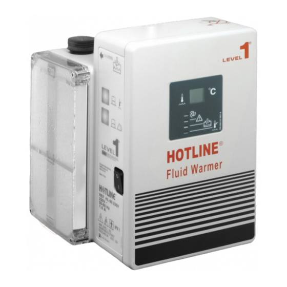
S E C T I O N H O T L I N E ® H L - 9 0 ® HOTLINE HL-90 Blood and Fluid Warmer ® The HOTLINE HL-90 Blood and Fluid Warmer is designed for ® use with the HOTLINE Warming Set to warm blood and IV fluids, and deliver them to the patient’s intravenous access site at normo- thermic temperatures under gravity flow conditions. -
Page 16: Features
S E C T I O N H O T L I N E ® H L - 9 0 Features ■ Integrated, highly effective design gives unparalleled ease of ■ Can be set up and operated in seconds ■ Warmed Intravenous Fluid delivery at up to 4750 ml/hr ■... -
Page 17: Specifications
S E C T I O N S p e c i f i c a t i o n s Specifications Dimensions inch Height 24.1 Length 21.0 Width 17.8 Weights Weight (dry) Weight (full) 11.0 Weight (as Shipped) 7.95 Electrical HL-90 US HL-90 UK... -
Page 18: Environmental
S E C T I O N S p e c i f i c a t i o n s Environmental Temperature Operating Range C — 45 10 — 95% RH, (non-condensing) Transport / Storage C — 70 5 — 95% RH, (non-condensing) Water Resistance Enclosure Protection IEC 60529, IP Code: IPX1... -
Page 19: Contra-Indications
S E C T I O N C o n t r a - i n d i c a t i o n s Contra-indications ■ Not Suitable for use in the presence of flammable anaesthetic mixtures with air or oxygen or with nitrous oxide. ®... - Page 20 Sub-Assemblies ® Blood and Fluid Warmer...
-
Page 21: Section 2 - Sub-Assemblies
S E C T I O N S u b - a s s e m b l i e s Sub-assemblies ® The principal sub-assemblies to be found in the HOTLINE HL-90 are: ■ The enclosure and chassis parts ■... -
Page 22: Enclosure
S E C T I O N E n c l o s u r e ( 1 ) Enclosure (1) ® HOT LINE Blood and Fluid Warmer Technical Service Pack... - Page 23 S E C T I O N E n c l o s u r e ( 2 ) Enclosure (2) Newer design Fillport Cover removes need for chain or retaining screw ® HOT LINE Blood and Fluid Warmer Technical Service Pack...
- Page 24 S E C T I O N E n c l o s u r e ( 3 ) Enclosure (3) ® HOT LINE Blood and Fluid Warmer Technical Service Pack...
-
Page 25: Recirculating Solution Path
S E C T I O N R e c i r c u l a t i n g S o l u t i o n P a t h Recirculating Solution Path ® HOT LINE Blood and Fluid Warmer Technical Service Pack... -
Page 26: Interlock Block
S E C T I O N I n t e r l o c k B l o c k Interlock Block ® HOT LINE Blood and Fluid Warmer Technical Service Pack... -
Page 27: Pcb Mounting
S E C T I O N P C B M o u n t i n g PCB Mounting ® HOT LINE Blood and Fluid Warmer Technical Service Pack... - Page 28 Technical Description ® Blood and Fluid Warmer...
-
Page 29: Section 3 - Technical Description
S E C T I O N T e c h n i c a l D e s c r i p t i o n Technical Description General ® The HOTLINE employs a safe recirculating solution heating ® system, inherently free of hotspots, to actively warm the HOTLINE Blood and Fluid Warming Set - a co-axial arrangement of warm... -
Page 30: Controls And Indicators
S E C T I O N T e c h n i c a l D e s c r i p t i o n Controls and Indicators Shows the current temperature of the circulating warmed recirculating solution. This steady GREEN indicator illuminates when power is ON and the Warming Set is correctly installed. - Page 31 S E C T I O N T e c h n i c a l D e s c r i p t i o n Mechanical (contd) The outer face of the reservoir is transparent so the recirculating solution level and flow can both be observed. A float switch is fitted in the tank, so that the unit cannot operate if there is insufficient recirculating solution to properly circulate.
-
Page 32: Electrical
S E C T I O N T e c h n i c a l D e s c r i p t i o n Electrical Power Circuits Line DPST Input F1 1.5A Filter F2 1.5A Contacts U501 Outlet R501 270R... -
Page 33: Control Circuit
S E C T I O N T e c h n i c a l D e s c r i p t i o n derived from a conventional step-down transformer. After rectification and smoothing, the supply is regulated to a nominal 10 volts by U501, an LM317T integrated regulator. - Page 34 S E C T I O N T e c h n i c a l D e s c r i p t i o n As a result, the current through the chain [control thermistor - R202 - R01/9] is roughly proportional to the recirculating solution temperature, and thus, so is the voltage sample at R202 slider.
-
Page 35: Digital Display
S E C T I O N T e c h n i c a l D e s c r i p t i o n Digital Display The temperature control thermistor is one of a pair, siamesed together in the heater housing. The other of these provides a user display of the recirculating solution temperature and, as we will see later, protection in case of failure by the first thermistor. -
Page 36: Thermistor Loss
S E C T I O N T e c h n i c a l D e s c r i p t i o n Thermistor Loss 78L05 LCD Module R601 R03/8 R607 178k 12 13 R03/3 O'temp Test U1.4 J101... - Page 37 S E C T I O N T e c h n i c a l D e s c r i p t i o n R03/6 R03/1 R302 R03/2 R304 R03/7 8.2M 100k R308 C301 15.4k µ 0.1 F U4.2 U2.4 R03/9...
-
Page 38: Over Temperature Alarm
S E C T I O N T e c h n i c a l D e s c r i p t i o n Over Temperature Alarm Earlier, we looked at how the display was generated from the second thermistor in the siamesed package. - Page 39 S E C T I O N T e c h n i c a l D e s c r i p t i o n Pressing the Alarm Test button artificially lowers the set point by making U3.6 short out R606. Since the set point is lowered to below room temperature, this should set off the alarm whatever the actual fluid temperature.
-
Page 40: Flasher
S E C T I O N T e c h n i c a l D e s c r i p t i o n R03/6 R03/1 R302 R03/2 R304 R03/7 8.2M 100k R308 C301 µ 15.4k 0.1 F U4.2 U2.4 R03/9... - Page 41 S E C T I O N T e c h n i c a l D e s c r i p t i o n The alarm LED does not return directly to the positive rail, as you might expect. Instead it gets its power from U2.4, which is configured as a low-frequency square-wave oscillator.
-
Page 42: Interlock Alarm
S E C T I O N T e c h n i c a l D e s c r i p t i o n Interlock Alarm R03/6 R03/1 R302 R03/2 R304 R03/7 8.2M 100k R308 C301 15.4k µ... -
Page 43: Recirculating Solution Level Alarm
S E C T I O N T e c h n i c a l D e s c r i p t i o n U3.7 is the Alarm Test circuit; if there is a fault in the alarm test switch, nothing happens except the unit will be unable to test its alarms. - Page 44 S E C T I O N T e c h n i c a l D e s c r i p t i o n Answer to the page 28 Puzzler As you probably guessed, it’s a bit of a trick question. The fact is that it really does look like the volume should increase, but this is apparently not the case.
- Page 45 Disassembly Procedures ® Blood and Fluid Warmer...
-
Page 46: Tools You Will Need
S E C T I O N T o o l s y o u w i l l n e e d Tools you will need ■ Needle-nose pliers ■ Philips head screwdriver ■ Small straight head screwdriver ■ inch A/F Allen key (hex wrench) ■... -
Page 47: Disassembly
S E C T I O N D i s a s s e m b l y Disassembly Step 1: Open the case ® WARNING: Ensure that the HOTLINE is disconnected from the Mains power. ® If the HOTLINE has been recently used, be aware that some interior components may be hot. - Page 48 S E C T I O N D i s a s s e m b l y Later models have only two front cover retaining screws, locat- ed under the unit. Again, it is not necessary to completely remove these screws.
-
Page 49: Step 2: Remove The Pcb
S E C T I O N D i s a s s e m b l y Step 2: Remove the PCB Remove connectors J2, J3, J4 by gently pulling on them. Figure 4 - 3: Disconnecting J3 Do not pull on the wiring, but grasp the connector body itself. It may be easier to use the needle-nose pliers. - Page 50 S E C T I O N D i s a s s e m b l y Remove the membrane switch ribbon connection from J1 by gently pulling it. Figure 4 - 4: Membrane Switch Connector Now release the mains input cable from the “Lego brick” termi- nals at the bottom front of the case.
- Page 51 S E C T I O N D i s a s s e m b l y Remove the eight wires from the terminals along the bottom edge of the PCB. To release the wires, each terminal’s orange tab must be pressed into the terminal body with pliers.
- Page 52 S E C T I O N D i s a s s e m b l y Alternatively, the tabs may be manipulated with a small straight screwdriver through the slot on the terminal’s top surface. Remove the four screws indicated. GM-0163_8408-GB-A Figure 4 - 7: PCB Mounting Points (Only on older models)
-
Page 53: Step 3: Release The Earth Stud
S E C T I O N D i s a s s e m b l y Step 3: Release the Earth Stud With the PCB removed, you will be able to see the external Earthing Stud which is attached to the chassis and passes out through the rear of the case. -
Page 54: Step 4: The Recirculating Solution Return Pipe
S E C T I O N D i s a s s e m b l y Step 4: The Recirculating Solution Return Pipe The recirculating solution return pipe emerges straight from the back of the interlock block and crosses the enclosure to the left- hand side, where it passes into the reservoir. -
Page 55: Step 5: Removing The Chassis
S E C T I O N D i s a s s e m b l y Step 5: Removing the Chassis Undo the four GM-0163_8411-GB-A poleclamp retaining screws from the rear of the chassis. Be ready to catch the poleclamp if it should fall off the back of the case. - Page 56 S E C T I O N D i s a s s e m b l y Slide the chassis forward at the left-hand side until you can re- lease the final silicone tube from the elbow beneath the interlock block.
-
Page 57: Reassembly
S E C T I O N R e a s s e m b l y Reassembly Reassembly is a straightforward process, consisting of following the aforementioned procedures in the reverse order. Measurements ® While you have the chance on a (presumed) good HOTLINE make a note of the following resistance measurements. -
Page 58: Section 5 - Maintenance, Testing And Calibration
Maintenance, Testing and Calibration ® Blood and Fluid Warmer... -
Page 59: Before Each Use
Lubricating the O-Ring Seals Using a cotton swab, apply a small amount of silicone grease (Smiths Medical Part Number EZL 80-04-002) to the O-Rings in the Disposable Set connector block. If this does not solve the problem, reject the unit. -
Page 60: Routine Maintenance Tasks
M a i n t e n a n c e Routine Maintenance Tasks Smiths Medical recommends that preventative maintenance be carried out at specified intervals. Some maintenance tasks need to be repeated at 30-day intervals and others at annual intervals, depending on your choice of recirculating solution. -
Page 61: Every 30 Days
S E C T I O N E v e r y d a y s Every 30 days ■ Perform a Visual Inspection looking for damage to the case, poleclamp, mains cable, etc. ■ Lubricate O-Ring Seals with a cotton swab, applying a small amount of silicone grease to the O-Rings. -
Page 62: Every 12 Months
S E C T I O N E v e r y M o n t h s Every 12 Months Alarm Testing ® Place the HOTLINE on a suitable firm surface. Visually check that the recirculating solution level in the reservoir is above the MIN mark. - Page 63 S E C T I O N E v e r y M o n t h s Over Temperature Alarm Test Allow the unit to run for sufficient time to stabilise the temperature. Press and hold the Over Temperature Alarm Test button.
- Page 64 S E C T I O N E v e r y M o n t h s Observe that: ■ the GREEN LED extinguishes. ■ the RED recirculating Solution Level LED lights up. the AUDIBLE ALARM commences beeping. ■ ■...
- Page 65 S E C T I O N E v e r y M o n t h s Replace O-Ring Seals GM-0163_8501-GB-A Figure 5 - 2: Getting access to the O-Ring Seals ■ Remove the socket head screws with an -inch Allen key.
- Page 66 S E C T I O N E v e r y M o n t h s Apply a smear of silicone grease (Smiths Medical Part ■ Number EZL 80-04-002) to two new O-Rings, and locate them in the sockets.
-
Page 67: Maintenance Solutions
If using plain distilled water as the recirculating fluid, then this must be changed at the 30-day service interval, using the procedure given here. Smiths Medical currently recommends using the Hydrogen Peroxide based recirculating solution which allows a 12-monthly recirculating solution change protocol, resulting in a significant reduction of service time. - Page 68 S E C T I O N M a i n t e n a n c e S o l u t i o n s Unplug the HOTLINE®. ■ ■ (Old case) Remove the Fill Port plug and hold the Unit over a sink to empty the water.
-
Page 69: Isopropyl Alcohol Solution
S E C T I O N M a i n t e n a n c e S o l u t i o n s Switch off and disconnect the Unit. ■ ■ Empty the unit once more. ■... -
Page 70: Hydrogen Peroxide Solution
S E C T I O N M a i n t e n a n c e S o l u t i o n s Switch off the HOTLINE® and dispose of the Disposable Set ■ in accordance with the usual procedures for your establishment. - Page 71 S E C T I O N M a i n t e n a n c e S o l u t i o n s establishment. Drain the fluid from the HOTLINE® and discard. ■ Refill the HOTLINE® with the second of the recirculating solution batches you made earlier.
- Page 72 S o l u t i o n s If you do not have a HOTLINE® TEMP CHECK thermometer, units may be returned to Smiths Medical for temperature verification. Set up the HOTLINE® ready for use as before. Attach the TEMP CHECK thermometer to the interlock block of the HOTLINE®...
-
Page 73: Routine Maintenance Checklists
S E C T I O N R o u t i n e M a i n t e n a n c e C h e c k l i s t s Routine Maintenance Checklists You may freely photocopy the checklists on the next three pages to act as a continuing record of your routine HOTLINE®... - Page 74 S E C T I O N R o u t i n e M a i n t e n a n c e C h e c k l i s t s ® HOT LINE Blood and Fluid Warmer Technical Service Pack...
- Page 75 S E C T I O N R o u t i n e M a i n t e n a n c e C h e c k l i s t s ® HOT LINE Blood and Fluid Warmer Technical Service Pack...
- Page 76 S E C T I O N ® HOT LINE Blood and Fluid Warmer Technical Service Pack...
-
Page 77: Full Service Test Procedure
Mains voltages are present inside. Avoid contact with any internal components not specified in this procedure. CAUTION: The Auxiliary Outlet is for use only with approved accessories supplied by your Smiths Medical distributor for that purpose. ® CAUTION: Do not fill the HOTLINE reservoir with a Disposable Set in place. -
Page 78: Hl-90 Service Test Specification
S E C T I O N 5 H L - 9 0 S e r v i c e T e s t S p e c i f i c a t i o n HL-90 Service Test Specification Setup Fill unit up with de-ionised water, attach an L-70 Disposable Set, turn on and let the HOTLINE®... - Page 79 S E C T I O N 5 H L - 9 0 S e r v i c e T e s t S p e c i f i c a t i o n Alarm Test Switch Depress the General Alarm Test switch.
- Page 80 S E C T I O N 5 H L - 9 0 S e r v i c e T e s t S p e c i f i c a t i o n If necessary, turn the “H2O” or “40” temperature set point adjustment pot clockwise to increase recirculating solution temperature, or counter-clockwise to decrease recirculating solution temperature.
- Page 81 S E C T I O N 5 H L - 9 0 S e r v i c e T e s t S p e c i f i c a t i o n [iii] The PCB display should increase to 43.6°C ± 0.3°C and then the Over Temperature Alarm should activate.
- Page 82 S E C T I O N 5 H L - 9 0 S e r v i c e T e s t S p e c i f i c a t i o n Other Territories Nominal Temperature Water Temperature Over Temperature (paragraph 6)
-
Page 83: Section 6 - Troubleshooting
Troubleshooting ® Blood and Fluid Warmer... -
Page 84: Troubleshooting Hints
S E C T I O N T r o u b l e s h o o t i n g H i n t s Troubleshooting Hints The following troubleshooting hints are organised into two groups - those involving alarm conditions and those that refer to conditions that do not normally incur an alarm. -
Page 85: Over Temperature Alarm Not Working
S E C T I O N T r o u b l e s h o o t i n g H i n t s Over Temperature Alarm not working Problem Possible Causes Remedial Action Display reading Over Temperature Alarm set point Recalibrate using TEMP CHECK. -
Page 86: Low Recirculating Solution Level Alarm Always On
S E C T I O N T r o u b l e s h o o t i n g H i n t s Recirculating Solution Level Alarm ON continuously Problem Possible Causes Remedial Action Recirculating Recirculating Solution really is low Add Recirculating Solution! Solution is Low. -
Page 87: Non-Alarm Related Faults
S E C T I O N T r o u b l e s h o o t i n g H i n t s Non-Alarm related Faults Problem Possible Causes Remedial Action No Power. Is the Unit plugged into a good Test socket with some other Mains powered socket and turned ON? device. -
Page 88: Section 7 - Spare Parts
Spare Parts ® Blood and Fluid Warmer... -
Page 89: Enclosure Parts For Two-Part Case
S E C T I O N H o t l i n e ® S p a r e P a r t s L i s t ® Hotline Spare Parts List For HL-90 with original style two-part case HL-90 Enclosure 64-02-005 HL-90 Front Cover... -
Page 90: Enclosure Parts For Single-Part Case
S E C T I O N H o t l i n e ® S p a r e P a r t s L i s t For HL-90 with single-part (1.5) case HL-90 1.5 Enclosure (badged for 115v) 78-03-090 HL-90 1.5 Enclosure (badged for 230v) 78-03-095... -
Page 91: Parts In The Recirculating Solution Path
S E C T I O N H o t l i n e ® S p a r e P a r t s L i s t Internal Recirculating Solution Path Parts 1/4 inch OD Silicone Tube 62-20-013 HL-90 Chassis 64-01-032 200W Heater ( 115V ) -
Page 92: And Mounting Accessories
S E C T I O N H o t l i n e ® S p a r e P a r t s L i s t PCB and Mounting Parts Item Description Part Number Assembled PC Board (US) 60-60-090 Assembled PC Board (Int) 70-02-096... -
Page 93: Interlock Block And Related Parts
S E C T I O N H o t l i n e ® S p a r e P a r t s L i s t Disposable Attachment and Interlock Parts Interlock Block 64-10-021 O-Ring Seal AS-568-108 62-40-010 O-Ring Lube 80-04-002... -
Page 94: External Parts, Rear Of Case
S E C T I O N H o t l i n e ® S p a r e P a r t s L i s t Rear External Parts Strain Relief 62-07-015 Strain Relief Nut 62-07-016 Line Cord Assembly (US) 70-01-093 Line Cord Assembly (Int) 70-01-091... -
Page 95: Poleclamp Parts
S E C T I O N H o t l i n e ® S p a r e P a r t s L i s t Pole Mounting Parts T-Bar Knob 64-10-027 Swivel Screw 62-05-022 Swivel Screw Foot 62-31-008 Poleclamp Block 64-10-026... - Page 96 Rounding Off ® Blood and Fluid Warmer...
-
Page 97: Section 8 - Rounding Off
S E C T I O N R o u n d i n g O f f Rounding Off This section collects together various loose ends, and in no particular order attempts to knit them together. Firstly, there’s the update history and modification status for the HOTLINE®... - Page 98 Figure 8 - 1: Location of components for two-second delay update This modification is not a safety related issue, so its implemen- tation is not mandatory. It is, however, recommended, and HOT- LINE® fluid warmers returned to Smiths Medical for service will be routinely updated with this modification. ®...
-
Page 99: Gri Pump
S E C T I O N R o u n d i n g O f f GRI Pump The original HOTLINE® units were manufactured with pumps made by March. This pump became unavailable in 1998 and an al- ternative pump, made by GRI was substituted. -
Page 100: Float Switch Sealing Washer
It is recommended that any black foam washer, whether or not it shows signs of degradation, be replaced with the new part made from orange silicone rubber. The part number remains as 62-40-011, and it is available FOC from your local Smiths Medical Distributor on request. ®... - Page 101 S E C T I O N R o u n d i n g O f f ® HOTLINE Quiz What is the maximum height above floor level allowed for a ® HOTLINE on an IV pole? 40 inches 42 inches 44 inches 46 inches...
- Page 102 S E C T I O N R o u n d i n g O f f What is the function of the control identified by this symbol? Switch on Heater Switch on Pump Test All Alarms Clear Airlock Which of these is not required by the 30-day routine mainte- nance? General Alarm Test...
- Page 103 S E C T I O N R o u n d i n g O f f Aside from Hydrogen Peroxide, which other active ingredient (at a suitable dilution strength) is specified as appropriate for ® disinfecting the HOTLINE ’s internal components? Ethyl Alcohol Isopropyl Alcohol...
- Page 104 Title of Training Program Trainee (optional) Location Program Presenter Date General 1) How did you (or your boss) find out about this course? Magazine advert Colleague (this establishment) S.M.I. Ltd Rep Colleague (another establishment) Other (what?) 2) How well did the course meet your training objectives? Completely Not at all 3) What objectives did it fail to meet?
- Page 105 Course Presentation 9) What was your opinion of the instructional materials provided with this course? (marks for (a) quality ... Not good Very good ... and (b) appropriateness) Not good Very good 10) What was your opinion of the A-V or multimedia aids (if any) used in this course? (marks for (a) quality ...
-
Page 106: Appendix 1- Circuits
Appendix 1- Circuits ® Blood and Fluid Warmer... - Page 107 A P P E N D I X C i r c u i t s ® HOT LINE Blood and Fluid Warmer Technical Service Pack...
- Page 108 A P P E N D I X C i r c u i t s ® HOT LINE Blood and Fluid Warmer Technical Service Pack...
- Page 109 A P P E N D I X C i r c u i t s ® HOT LINE Blood and Fluid Warmer Technical Service Pack...
-
Page 110: Appendix 2 - Pcb Layout
Appendix 2 - ® PCB Layout Blood and Fluid Warmer... - Page 111 A P P E N D I X P C B l a y o u t PCB layout F3 CR1 VOLTAGE C2(below) SIDE Transformer T1 (below) U501 HIGH VOLTAGE SIDE K1 (below) U102 R401 R607 (below) R103 R606 C101 (below) R301 R203 C301...
-
Page 112: Component Listing
L i s t i n g Component Listing ■ This listing is for information only. None of the parts listed be- low are offered by Smiths Medical as spare parts. ■ For the complete list of all available spare parts, please see sec- tion 6. - Page 113 A P P E N D I X C o m p o n e n t L i s t i n g Resistors 15k x 9 way R201 16K5 R401 15k x 7 way R202 5K POT R501 433R 15k x 9 way R203...
- Page 114 A P P E N D I X C o m p o n e n t L i s t i n g Capacitors Miscellaneous 100 pF LS301 Piezo-Sounder µ C101 µ µ C201 µ C301 µ C302 µ C501 ®...
- Page 115 ® Blood and Appendix 3 - Symbols Glossary Fluid Warmer...
-
Page 116: Appendix 3 - Symbols Glossary
A P P E N D I X S y m b o l s G l o s s a r y Symbols Glossary Symbol Meaning Read Instructions before use or (failing that) Disposable Interlock Alarm. The Warming Set is not connected correctly, and must be reattached before proceeding. - Page 117 A P P E N D I X S y m b o l s G l o s s a r y Symbol Meaning Test Button that simulates the Over Temperature Alarm condition. The Over Temperature Alarm lamp should light up, and the audible alarm should sound repetitively.
- Page 118 ® Blood and Fluid Warmer Appendix 4 - Frequently Asked Questions Information Bulletins...
- Page 119 A P P E N D I X F r e q u e n t l y A s k e d Q u e s t i o n s Frequently Asked Questions These are general Questions and their Answers about various ®...
- Page 120 A P P E N D I X F r e q u e n t l y A s k e d Q u e s t i o n s warmed, it must be done so as not to cause hemolysis." In the abstract, "The Effect of Heat on In-Vitro Parameters of Red Cell Integrity", presented at the 46th Annual Meeting of the AABB, Uhl, Pacini and Kruskall state that "subtle...
- Page 121 Test the fault condition alarms Verify the temperature calibration ■ If you operate your HOTLINE® with an approved microbicidal solution as the recirculating solution (as recommended by Smiths Medical), the following maintenance will be needed: ■ Monthly: Lubricate the O-Rings with silicone lubricant Annually: ■...
- Page 122 A P P E N D I X F r e q u e n t l y A s k e d Q u e s t i o n s ■ Is my disposable sterile? ® ■ All Level 1 IV disposables are labeled with "sterile fluid ®...
-
Page 123: General Advisement
A P P E N D I X G e n e r a l A d v i s e m e n t General Advisement These Customer Information Bulletins are included for histori- cal completeness. They relate to subjects that were significant at the time of issue. -
Page 124: Hotline ® - Specific Announcements
A P P E N D I X H O T L I N E ® - S p e c i f i c A n n o u n c e m e n t s ® HOTLINE - Specific Announcements Topic Original Format... - Page 125 A P P E N D I X H O T L I N E ® - S p e c i f i c A n n o u n c e m e n t s Figure A4 - 1: Extension of the maintenance interval to 6 months - page 1 ®...
- Page 126 A P P E N D I X H O T L I N E ® - S p e c i f i c A n n o u n c e m e n t s Figure A4 - 2: Extension of the maintenance interval to 6 months - page 2 ®...
- Page 127 A P P E N D I X H O T L I N E ® - S p e c i f i c A n n o u n c e m e n t s Figure A4 - 3: Extension of the maintenance interval to 12 months - page 1 ®...
- Page 128 A P P E N D I X H O T L I N E ® - S p e c i f i c A n n o u n c e m e n t s Figure A4 - 4: Extension of the maintenance interval to 12 months - page 2 ®...
- Page 129 A P P E N D I X H O T L I N E ® - S p e c i f i c A n n o u n c e m e n t s Figure A4 - 5: Extension of the maintenance interval to 12 months - page 3 ®...
- Page 130 WEB ANNOUNCEMENT A P P E N D I X H O T L I N E ® - S p e c i f i c A n n o u n c e m e n t s ONE-YEAR MAINTENANCE PROTOCOL ®...
- Page 131 A P P E N D I X M e m o r a n d u m Memorandum Smiths Medical ASD, Inc. Anesthesia and Safety Devices Division 160 Weymouth Street Rockland MA 02370 USA Tel: 781 878 8011 Fax: 781 878 8201 www.smiths-medical.com...
- Page 133 European Representative: Smiths Medical International Ltd., Ashford, Kent, TN25 4BF, UK Tel +44 (0) 1233 722100 Australian Representative: Smiths Medical Australasia Pty. Ltd., Eight Mile Plains, QLD 4113, Australia Tel +61 (0) 7 3340 1300, Fax +61 (0) 7 3340 1399 www.smiths-medical.com...
Need help?
Do you have a question about the LEVEL 1 HOTLINE HL-90 and is the answer not in the manual?
Questions and answers