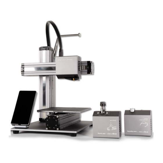
Snapmaker A150 User Manual
Hide thumbs
Also See for A150:
- Quick start manual (81 pages) ,
- Quick start manual (41 pages) ,
- Quick start manual (25 pages)
Table of Contents
Advertisement
Quick Links
Advertisement
Chapters
Table of Contents
Troubleshooting

Related Manuals for Snapmaker A150


Summary of Contents for Snapmaker A150
-
Page 2: Foreword
Foreword This manual instructs you to use the Snapmaker 2.0 A150, A250, and A350. The three models with different sizes share the same 3-in-1 function, so we will demonstrate their use with the A350 model. Before operation, ensure that you have read the entire manual. -
Page 3: Table Of Contents
Contents Foreword Contents Safety Guidelines Labels on Your Snapmaker Safety Symbols Safety Measures Emergency Response Touchscreen User Interface Firmware Snapmaker Luban How to Install Version Requirements 3D Printing 01 Operating Environment 02 Filament Library 03 How to 3D Print 04 Waste Disposal... - Page 4 03 How to Laser Engrave and Cut 04 Waste Disposal 05 Maintenance 06 Troubleshooting CNC Carving 01 Operating Environment 02 Material Library 03 Tool Library 04 How to CNC Carve 05 Waste Disposal 06 Maintenance 07 Troubleshooting Resources Compliance Disclaimer Copyright...
-
Page 5: Safety Guidelines
Safety Guidelines... -
Page 6: Labels On Your Snapmaker
Safety Guidelines - Labels on Your Snapmaker Labels on Your Snapmaker On the 3D Printing Module Warns you of the hot surface. Avoid direct contact with the nozzle and hot end during printing or immediately after printing. On the Laser Module Warns you of laser radiation. - Page 7 Do not print directly on this surface; otherwise, you will damage the Heated Bed. Do not touch the Heated Bed with bare hands during printing or immediately after printing. There are no labels on the Heated Bed on Snapmaker 2.0 A150. Nevertheless, you should remain cautious in operation.
-
Page 8: Safety Symbols
Safety Guidelines - Labels on Your Snapmaker Safety Guidelines - Safety Symbols On the Print Sheet Warns you of danger. Pay attention to any operations on the Print Sheet. Warns you of the hot surface. Avoid direct contact with the Print Sheet during printing or immediately after printing. -
Page 9: Safety Measures
Safety Guidelines - Labels on Your Snapmaker Safety Guidelines - Safety Measures Safety Guidelines - Safety Measures Safety Measures General Safety Information Read the entire manual before use. This machine should only be used by trained operators aged 18 and above. -
Page 10: Emergency Response
Safety Guidelines - Labels on Your Snapmaker Safety Guidelines - Safety Measures Safety Guidelines - Emergency Response CNC Safety Always operate the machine wearing the CNC Safety Goggles. Operate the CNC carver in a well-ventilated place and take safety precautions like wearing protective masks. - Page 11 Safety Guidelines - Labels on Your Snapmaker Safety Guidelines - Emergency Response Skin Injury from Laser Lasers can harm the skin via photochemical or thermal burns, which can be treated as could any other burn. Take the following steps as an emergency response: (1) If it is a major burn, call for emergency medical care before you take the subsequent steps.
- Page 12 Safety Guidelines - Labels on Your Snapmaker Safety Guidelines - Emergency Response (1) If the fire is small in size (no larger than a small trash can), you can use an extinguisher to put it out. Remember to cut electrical power before dousing the flame.
-
Page 13: Touchscreen
Touchscreen... -
Page 14: User Interface
Safety Guidelines - Touchscreen Touchscreen - User Interface Touchscreen - User Interface User Interface Home Screen Wireless Network Machine Name Toolhead Name Green indicates normal status Parts Name Orange indicates abnormal status Swipe left Key Parameter Start working by selecting files APP List Screen 3DP: Control the movement, nozzle temperature, and Heated Bed temperature... -
Page 15: Firmware
Firmware Update > Check for Updates > Update Now > Complete. : Download our firmware from snapmaker.com/product/snapmaker-2/downloads > Insert the USB flash drive into the Controller > Turn on the machine > Swipe left on the Touchscreen > Tap Files > USB > Tap the firmware file to update. -
Page 16: Snapmaker Luban
Safety Guidelines - Touchscreen Snapmaker Luban User Manual |... -
Page 17: How To Install
Safety Guidelines - Touchscreen Snapmaker Luban - How to Install How to Install Our free slicing Software Snapmaker Luban (Luban hereafter) supports three operating systems. - Windows - macOS - Linux Download Luban from luban.xyz or Forum. Double-click and install Luban. -
Page 18: Printing
3D Printing... - Page 19 Filament Holder Linear Module (X Axis) Hot End Kit Nozzle 3D Printing Module (Toolhead) Controller Filament Linear Modules (Z Axes) Support Platform Print Sheet Heated Bed Touchscreen Linear Modules (Y Axes) Base Plate Power Module...
-
Page 20: Operating Environment
01 Operating Environment 1.1 Temperature and Humidity 1.2 Workbench 02 Filament Library 2.1 Filament Overview 2.2 PLA 2.3 ABS 2.4 TPU 2.5 PETG 03 How to 3D Print 3.1 3D Printing Workflow 3.2 Level the Heated Bed 3.3 Load the Filament 3.4 Prepare the G-code File 3.5 Transfer the File and Start Printing 3.6 Remove Prints... - Page 21 5.3 Every Month 5.4 Every Three Months 06 Troubleshooting 6.1 First Layer Does Not Stick 6.2 Warping 6.3 Toolhead Hits the Heated Bed 6.4 Filament Does Not Come Out 6.5 Blobs on Nozzle...
-
Page 22: Temperature And Humidity
3D Printing - 01 Operating Environment 01 Operating Environment 1.1 Temperature and Humidity 1.1.1 Recommended Temperature The Fused Deposition Modeling (FDM) technology is highly susceptible to temperature. To ensure a perfect print result, put the 3D printer at a recommended ambient temperature. The recommended operating temperature for your 3D printer is between 0°C to 40°C (32°F to 104°F). -
Page 23: Filament Overview
3D Printing - 02 Filament Library 02 Filament Library 2.1 Filament Overview Your 3D printer support filaments including PLA, ABS, TPU, PETG, more being tested. Filament Properties Application Easy to print, environmentally friendly, degradable, food safe, high tensile Medical devices, food handling, packaging, strength, low shrinkage, variety in automotive components color... -
Page 24: Pla
3D Printing - 02 Filament Library 2.2 PLA Filament Properties Physical Properties Diameter 1.75 mm Density 1.2 g/cm Thermal Properties Melt Flow Index 3.5 g/10 min Heat Deflection Temperature 53°C (127.4°F) Mechanical Properties Flexural Strength 90 MPa (13 ksi) Flexural Modulus 1,915 MPa (277.7 ksi) Impact Strength 5.4 KJ/m... -
Page 25: Abs
3D Printing - 02 Filament Library 2.3 ABS Filament Properties Physical Properties Diameter 1.75 mm Density 1.06 g/cm Thermal Properties Heat Deflection Temperature 73°C (163.4°F) Mechanical Properties Flexural Strength 68 Mpa (9.9 ksi) Flexural Modulus 1,203 Mpa (174.5 ksi) Tensile Strength 40 MPa (5.8 ksi) Impact Strength 42 KJ/m... -
Page 26: Tpu
3D Printing - 02 Filament Library 2.4 TPU Filament Properties Physical Properties Diameter 1.75 mm Density 1.21 g/cm Thermal Properties Melt Flow Index 1.2 g/10 min Mechanical Properties Tensile Strength 35 MPa (5.1 ksi) Elongation at Break 800% Printing Parameters Printing Temperature 230°C–250°C (446°F–482°F) Heated Bed Temperature... - Page 27 3D Printing - 02 Filament Library Density 1.38 g/cm Thermal Properties Melt Flow Index 20 g/10 min Heat Deflection Temperature 64°C (147.2°F) Mechanical Properties Flexural Strength 68 Mpa (9.9 ksi) Flexural Modulus 1,800 Mpa (261.1 ksi) Tensile Strength 49 MPa (7.1 ksi) Impact Strength 7.6 KJ/m Elongation at Break...
-
Page 28: Printing Workflow
3D Printing - 03 How to 3D Print 03 How to 3D Print 3.1 3D Printing Workflow ⇩ Pre-check ⇩ Level the Heated Bed ⇩ Load the Filament ⇩ Prepare the G-code File ⇩ Transfer the G-code File ⇩ Start Printing Remove the Print Before printing, you should thoroughly check the 3D printer and filament (see 5.2 Before You Print... - Page 29 3D Printing - 03 How to 3D Print Auto Leveling (1) Turn on the 3D printer. (2) Read instructions. On the Touchscreen, swipe left to tap Calibration. Read on-screen instructions on how to level the bed and tap Start to run Auto Leveling. (3) Start calibrating.
- Page 30 3D Printing - 03 How to 3D Print b. Fine-tune the last point. Select the offset per travel (0.05 mm, 0.1 mm, or 0.5 mm). Keep adjusting the height of the nozzle tapping Up and Down, until you feel slight resistance when you pull out the Calibration Card and it should be wrinkled when you push it forward.
- Page 31 3D Printing - 03 How to 3D Print (3) Calibrate the first point. Place the Calibration Card or a piece of paper between the nozzle and Print Sheet. (4) Fine-tune the first point. Select the offset per travel (0.05 mm, 0.1 mm, or 0.5 mm). Keep adjusting the height of the nozzle tapping Up and Down, until you feel slight resistance when you pull out the Calibration Card and it should be wrinkled when you push it forward.
- Page 32 3D Printing - 03 How to 3D Print (5) Calibrate the rest of the points. One by one, repeat the previous two steps till the last point. Tap Save to save the calibration settings. Calibration Grid Your 3D printer has three types of calibration grids, made up respectively of 9, 16, or 25 points. At each point, the distance sensor probes the height of the Heated Bed, and then the 3D printer records the data.
- Page 33 3D Printing - 03 How to 3D Print To switch the calibration grids, tap Settings > 3D Printing > Calibration Grid on the Touchscreen. 9-Point Grid This grid is 2 × 2, with 9 points. To apply it, tap 3 and Save. 16-Point Grid This grid is 3 ×...
-
Page 34: Load The Filament
3D Printing - 03 How to 3D Print 25-Point Grid This grid is 4 × 4, with 25 points. To apply it, tap 5 and Save. 3.3 Load the Filament Your 3D printer supports two filament loading modes——Auto Loading and Manual Loading, as is the case with filament unloading. - Page 35 3D Printing - 03 How to 3D Print (2) Insert the filament. During heating, hang the filament onto the Filament Holder. Cut the bent end of the filament using the diagonal pliers, and insert it into the 3D Printing Module. Should the 3D Printing Module have filament inserted, heat the nozzle up to 200°C (392°F) and then tap Unload to pull out the old filament before inserting a new one.
- Page 36 3D Printing - 03 How to 3D Print (4) Clean the nozzle using the tweezers. Do not touch the hot nozzle with bare hands. Manually Load the Filament (1) Heat the nozzle. On the APP List Screen, tap Control > Nozzle. Slide the scale bar left or right to set the target Nozzle Temp.
- Page 37 3D Printing - 03 How to 3D Print (2) Insert the filament. During heating, hang the filament to the Filament Holder. Cut the bent end of the filament using the diagonal pliers, and insert it into the 3D Printing Module. Should the 3D Printing Module have filament inserted, heat the nozzle up to 200°C (392°F) and then tap Unload to pull out the old filament before inserting a new one.
-
Page 38: Prepare The G-Code File
3D Printing - 03 How to 3D Print Do not touch the hot nozzle with bare hands while operating the slide knob. (4) Manually extrude the filament. After the nozzle reaches the target temperature, squeeze the filament down the feed hole until the uncured filament is extruded from the nozzle. Press the slide knob inward and then push it right to close the 3D Printing Module. -
Page 39: Transfer The File And Start Printing
• As a reminder, Luban supports these design file formats for 3D printing: .stl, .obj, more formats to be added. Generate the G-code File Open Luban and follow the Snapmaker 2.0 Quick Start Guide to generate the G-code file. 3.5 Transfer the File and Start Printing You can transfer the G-code file to Touchscreen or keep it on Luban for printing. - Page 40 3D Printing - 03 How to 3D Print (5) On the Touchscreen, find the G-code file by tapping Files > Local. Preview the file, check the printing settings, and tap Start to start printing. Should the first layer fail to stick to the Print Sheet, Stop printing and see 6.1 First Layer Does Not Stick.
- Page 41 3D Printing - 03 How to 3D Print Should the first layer fail to stick to the Print Sheet, Stop printing and see 6.1 First Layer Does Not Stick. During printing, you can readjust settings by swiping left on the printing screen. Start Printing on Luban via Workspace (1) In the 3D Printing G-code Generator, load the generated G-code file to Workspace by clicking Load G-code to Workspace.
- Page 42 If you can’t find the port, unplug the USB cable and try again. For initial use, you need to download and install the driver from snapmaker.com/product/snapmaker-2/downloads. (4) After connection, Luban will prompt you to select your machine model and toolhead. Select and click Choose to save the settings.
-
Page 43: Remove Prints
3D Printing - 03 How to 3D Print 3.6 Remove Prints Bend the Print Sheet (1) Wait several minutes until the nozzle and Heated Bed cool down to the ambient temperature as indicated by the Touchscreen. Remove the Print Sheet from the Heated Bed, and slightly bend the Print Sheet to detach the print edge from the Print Sheet. - Page 44 3D Printing - 03 How to 3D Print Tape the Print Sheet To remove the print with ease, you can tape the Print Sheet before printing. (1) Clean the Print Sheet surface with alcohol. (2) Tape the Print Sheet using adhesive tapes (≥ 1 mm) that are resistant to high temperature. Apply pressure to the tapes to smooth out air bubbles underneath using the flat blade.
- Page 45 3D Printing - 03 How to 3D Print (3) Trim the tape to fit the Print Sheet edge. (4) Tape the entire Print Sheet. Ensure that the two sides of all tapes fit tightly, without any gaps. (5) Since the printing will be performed on the tape, you should recalibrate the Heated Bed before printing. User Manual |...
- Page 46 As a general rule, you should always remove support structures slowly and cautiously. Diagonal Pliers Provided by Snapmaker. Diagonal pliers with wide jaws are typically used for cutting off outer parts, but less ideal for parts embedded deep inside the model.
-
Page 47: Filament Runout Recovery
3D Printing - 03 How to 3D Print Needle Nose Pliers Not provided. Needle nose pliers with long and narrow noses are typically used for grabbing away parts quickly, but less suitable for parts that need precise control. Precision Knives Not provided. -
Page 48: Power Loss Recovery
3D Printing - 03 How to 3D Print 3.8 Power Loss Recovery If the Power Module is turned off, to resume the printing job: (1) Turn on the power switch. (2) After the 3D printer is restarted, tap Resume on the Touchscreen. If the AC Power Cable is unplugged, to resume the printing job: (1) Turn off the power switch. -
Page 49: Maintenance
5.1 Maintenance Schedule This maintenance schedule is for reference only. Should you use the 3D printer more frequently, adjust your schedule according to your use frequency. Before maintenance, check Snapmaker’s Limited Warranty void your warranty by self-servicing your 3D printer. -
Page 50: Before You Print
Update the Firmware and Software 5.2 Before You Print 5.2.1 Check the Cables Check if every cable is plugged into the right socket in the right direction. Into the Controller (A150) Toolhead Cable X Conversion Cable Y Conversion Cable Z Conversion Cable... - Page 51 Into the Controller (A250 & A350) Toolhead Cable X Conversion Cable Y Conversion Cable Z Conversion Cable Heated Bed DC Power Cable Touchscreen Cable USB Flash Drive Into the Converters Z Cables Y Cables Converters Snapmaker 2.0 A150 has no Converters. User Manual |...
- Page 52 3D Printing - 05 Maintenance On the 3D Printing Module 5.2.2 Check the Support Platform Check if the Support Platform is assembled in the correct direction. The front without screws should face up, and the rear with some screws faces down. If you install the platform upside down, it will be higher than the one when it is correctly installed, and this is likely to cause the 3D Printing Module to bump into the Print Sheet.
- Page 53 3D Printing - 05 Maintenance 5.2.3 Check the Heated Bed Check if the Heated Bed is flat and stable, fully tightened with screws. If not, reassemble the Heated Bed. Flat Slant Check if the Print Sheet is correctly placed on the Heated Bed as illustrated. If not, reassemble the Print Sheet. Flat Waved Bumped...
- Page 54 3D Printing - 05 Maintenance b. Clean the bore. After the nozzle reaches the target temperature, insert a needle, with its diameter smaller than 0.4 mm, into the nozzle bore from the bottom. Do not use pliers, scissors, or drill bits to clean the nozzle as they may damage the nozzle. Do not touch the hot nozzle with bare hands.
- Page 55 3D Printing - 05 Maintenance c. Stir the softened filament out using the needle until you have cleared the blockage. d. Check if the nozzle is clean. Tap Load and insert the filament to see if it can get through the nozzle. If not, re- peat the previous two steps to clear the blockage.
- Page 56 3D Printing - 05 Maintenance Clean the Nozzle Tip Clean the nozzle tip and its surrounding area with a swab. 5.2.5 Check the Filament Before you print, check if the filament is damp. Here are some tips to identify, store, and dry the filament. How to Identify Damp Filaments These are a few common signs of damp filaments: •...
- Page 57 Note that drying temperature and drying time vary with filament types, brands, and quantities. Before drying, check the optimal drying temperature and drying time for your damp filament. If the filament is still damp, you can buy new filaments from Snapmaker's online store. User Manual |...
-
Page 58: Every Month
To do so, gently wipe the Linear Module surface using a dry cotton cloth. While cleaning, do not press the steel strip. Do not dismantle the Linear Modules yourself, as doing so will void your Snapmaker’s Limited Warranty. 5.3.2 Clean the Gear in the 3D Printing Module While driving the filament into the extruder, the gear encounters strong friction, which more or less produces scraps. - Page 59 3D Printing - 05 Maintenance b. Clean the gear. Clear the accumulated scraps on the gear and its surrounding area using a swab. Close the 3D Printing Module. User Manual |...
-
Page 60: Every Three Months
3D Printing - 05 Maintenance 5.3.3 Clean the Side Covers The 3D Printing Module has two side covers, each with vents and a dust-proof net for heat dissipation. If the side covers are clogged by foreign matters, it will affect the airflow inside the 3D Printing Module. Consequently, the internal components will be overheated, and the 3D Printing Module will malfunction. -
Page 61: Troubleshooting
3D Printing - 06 Troubleshooting 06 Troubleshooting 6.1 First Layer Does Not Stick Possible Causes (1) The calibration is done improperly. (2) The printing parameters are improper. (3) The Print Sheet is dirty and thus uneven. (4) The nozzle bore or tip is dirty. (5) The filament is damp. - Page 62 3D Printing - 06 Troubleshooting b. Return to the APP List Screen, and tap Calibration > Start to run Heated Auto Leveling. c. Slide the scale bar to the recommended temperature as indicated by the Touchscreen. After the Heated Bed reaches the target temperature, tap Calibrate. d.
-
Page 63: Warping
3D Printing - 06 Troubleshooting Caution the hot Heated Bed. Always wear heat-resistant gloves while using the Heated Auto Leveling or Heated Manual Leveling mode. (3) Reset the printing parameters on Luban: a. Set the Heated Bed Adhesion Type as Brim. Brim can effectively improve the first layer adhesion. Also, you can increase the line count to improve adhesion. - Page 64 (3) Check if the screws for attaching the 3D Printing Module are installed into the correct holes. (4) Check if the Support Platform is correctly installed (see 5.2.2 Check the Support Platform). If not, reassemble the Support Platform. (5) If the problem persists, contact us at support@snapmaker.com. User Manual |...
-
Page 65: Filament Does Not Come Out
To begin with, heat the nozzle up to 230°C (446°F), and replace the hot end with a spare one provided in the box. (1) See 6.1 First Layer Does Not Stick. (2) Replace it with a quality filament. If the problem persists, contact us at support@snapmaker.com. User Manual |... -
Page 66: Laser Engraving And Cutting
Laser En- graving and Cutting... - Page 67 Laser Engraving and Cutting Module (Toolhead) Camara Light Built-in Camara Linear Module (X Axis) Lens Hood Controller Linear Module (Z Axes) Support Platform Laser Safety Goggles Laser Engraving and Cutting Platform Touchscreen Linear Modules (Y Axes) Base Plate Power Module...
-
Page 68: Operating Environment
01 Operating Environment 1.1 Work Area 1.2 Workbench 02 Material Library 2.1 Material Overview 2.2 Wood 2.3 Basswood (1.5 mm) 2.4 MDF 2.5 Vegetable-tanned Leather (1.5 mm) 2.6 Cotton Fabric (0.6 mm) 2.7 A4 White Paper (0.1 mm) 2.8 White Cardstock (0.28 mm) 2.9 Corrugated Fiberboard (3 mm) 2.10 Non-transparent Acrylic (2.6 mm) 03 How to Laser Engrave and Cut... -
Page 69: Waste Disposal
3.11 Power Loss Recovery 3.12 Other Operations 04 Waste Disposal 4.1 Package 4.2 Waste Gas Treatment 4.3 Wasted Material 4.4 Electronics 05 Maintenance 5.1 Maintenance Schedule 5.2 Before You Engrave and Cut 5.3 Every Month 5.4 Every Three Months 06 Troubleshooting 6.1 Auto Focus Fails 6.2 Camera Capture Does not Work 6.3 Laser Is Discontinuous or Weak... -
Page 70: Work Area
Laser Engraving and Cutting - 01 Operating Environment 01 Operating Environment 1.1 Work Area 1.1.1 Ventilation Always use the laser engraving and cutting machine in a well-ventilated area. The machine uses a laser beam to rapidly heat, melt and partially or completely vaporize the material, creating gases and particulate matter. These byproducts of laser operation may irritate the eyes and respiratory system. -
Page 71: Material Overview
Laser Engraving and Cutting - 02 Material Library 02 Material Library 2.1 Material Overview Snapmaker 2.0 laser engraving and cutting machine supports materials including wood, basswood, MDF, vegetable-tanned leather, cotton fabric, A4 white paper, white cardstock, corrugated fiberboard, non-transparent acrylic, and more are being tested. -
Page 72: Wood
Laser Engraving and Cutting - 02 Material Library 2.2 Wood Work Parameters Engraving in Line Mode Density 5 dot/mm Work Speed 500 mm/min Power 100% Engraving in Dot Mode Density 5 dot/mm Work Speed 2500 mm/min Dwell Time 5 ms/dot Power 2.3 Basswood (1.5 mm) Work Parameters... -
Page 73: Mdf
Laser Engraving and Cutting - 02 Material Library Power Cutting Work Speed 180 mm/min Passes Pass Depth 0.6 mm Power 100% 2.4 MDF Work Parameters Engraving in Line Mode Density 5 dot/mm Work Speed 800 mm/min Power Engraving in Dot Mode Density 5 dot/mm Work Speed... -
Page 74: Vegetable-Tanned Leather (1.5 Mm)
Laser Engraving and Cutting - 02 Material Library 2.5 Vegetable-tanned Leather (1.5 mm) Work Parameters Engraving in Line Mode Density 5 dot/mm Work Speed 800 mm/min Power Engraving in Dot Mode Density 5 dot/mm Work Speed 2500 mm/min Dwell Time 5 ms/dot Power Cutting... -
Page 75: Cotton Fabric (0.6 Mm)
Laser Engraving and Cutting - 02 Material Library 2.6 Cotton Fabric (0.6 mm) Work Parameters Engraving in Line Mode Density 5 dot/mm Work Speed 500 mm/min Power Engraving in Dot Mode Density 5 dot/mm Work Speed 2500 mm/min Dwell Time 5 ms/dot Power Cutting... -
Page 76: A4 White Paper (0.1 Mm)
Laser Engraving and Cutting - 02 Material Library 2.7 A4 White Paper (0.1 mm) Work Parameters Cutting Work Speed 1100 mm/min Passes Pass Depth 0.6 mm Power 100% User Manual |... -
Page 77: White Cardstock (0.28 Mm)
Laser Engraving and Cutting - 02 Material Library 2.8 White Cardstock (0.28 mm) Work Parameters Engraving in Line Mode Density 5 dot/mm Work Speed 800 mm/min Power Engraving in Dot Mode Density 5 dot/mm Work Speed 2500 mm/min Dwell Time 5 ms/dot Power Cutting... -
Page 78: Corrugated Fiberboard (3 Mm)
Laser Engraving and Cutting - 02 Material Library 2.9 Corrugated Fiberboard (3 mm) Work Parameters Engraving in Line Mode Density 5 dot/mm Work Speed 500 mm/min Power Engraving in Dot Mode Density 5 dot/mm Work Speed 2500 mm/min Dwell Time 5 ms/dot Power Cutting... -
Page 79: Non-Transparent Acrylic (2.6 Mm)
100% 03 How to Laser Engrave and Cut 3.1 Laser Engraving and Cutting Workflows Snapmaker provides you with the following two methods to help you position the laser working area: • Use Camera Capture • Set Work Origin If you use the method of camera capture, you must connect your machine to Luban, and use Luban for the subsequent operations. - Page 80 Laser Engraving and Cutting - 03 How to Laser Engrave and Cut Use Camera Capture to Start Laser Engraving and Cutting in Luban ⇩ Pre-check the Machine ⇩ Measure the Focal Length ⇩ Calibrate the Camera ⇩ Prepare the Material to Engrave or Cut ⇩...
-
Page 81: Measure The Focal Length
Focal Length Focal Point Axis Snapmaker designs both the Auto Focus and Manual Focus modes to help you measure the focal length. The measurement of focal length mainly involves the following procedures. (1) Engrave a few lines at different heights. - Page 82 Laser Engraving and Cutting - 03 How to Laser Engrave and Cut The manual focusing procedure does not necessarily use the default value for focal length. Instead, you can manually set a reference point. Then, the machine adjusts the height of the Laser Module based on the reference point to engrave a series of lines on the material.
- Page 83 Laser Engraving and Cutting - 03 How to Laser Engrave and Cut (3) Calculate and record the focal length. After the best engraved line is identified, automatically or manually, the machine will register the corresponding laser height and calculate the focal length, which will be saved for subsequent use. As long as you do not reassemble the Laser Module and the machine works normally, the recorded focal length can be used for the next engraving and cutting job.
- Page 84 Laser Engraving and Cutting - 03 How to Laser Engrave and Cut (2) On the Touchscreen, swipe left to tap Calibration. (3) Read the homing instruction on the Touchscreen. Tap Going Home, and the Laser Module will automatically jog to the starting position of X, Y, and Z axes. If you have completed homing previously, the machine will skip this step.
- Page 85 Laser Engraving and Cutting - 03 How to Laser Engrave and Cut (4) Slide the scale to set the thickness of the material (1.5 mm) and tap Next. (5) Put the Calibration Card provided or a piece of A4 paper in between the Laser Module and the material. Tap X-, X+, Y-, Y+ to move the Laser Module above the Calibration Card.
- Page 86 Laser Engraving and Cutting - 03 How to Laser Engrave and Cut (6) Put on the Laser Safety Goggles and tap Next. (7) Tap Set Work Origin, and then tap Run Boundary. As the Laser Module moves, the laser dot will be traveling along the path of a small rectangle on the material surface, which represents the area to be engraved.
- Page 87 Laser Engraving and Cutting - 03 How to Laser Engrave and Cut (9) After Auto Focus is completed, tap Complete to go back to the APP List Screen. If the screen displays Failed, tap Failed and slide the scale to choose the line corresponding to the thinnest engraved line manually.
- Page 88 Laser Engraving and Cutting - 03 How to Laser Engrave and Cut Manually Measure the Focal Length Preparation: Laser Material × 1 Silicone Plugs × 4 Laser Safety Goggles × 1 (1) Place the provided material on the Laser Engraving and Cutting Platform. Secure it with the silicone plugs. (2) On the Touchscreen, swipe left to tap Calibration.
- Page 89 Laser Engraving and Cutting - 03 How to Laser Engrave and Cut (3) Read the homing instruction on the Touchscreen. Tap Going Home, and the Laser Module will automatically jog to the starting position of X, Y, and Z axes. If you have completed homing previously, the machine will skip this step.
- Page 90 Laser Engraving and Cutting - 03 How to Laser Engrave and Cut (5) Put the Calibration Card provided or a piece of A4 paper in between the Laser Module and the material. Tap X-, X+, Y-, Y+ to move the Laser Module above the Calibration Card. Keep adjusting the Z Offset until you feel slight resistance when you pull out the Calibration Card, and it should be wrinkled when you push it forward.
- Page 91 Laser Engraving and Cutting - 03 How to Laser Engrave and Cut Too close Perfect Too far (8) Tap Set Work Origin, and then tap Run Boundary. As the Laser Module moves, the laser dot will be travelling along the path of a small rectangle on the material surface, which represents the area to be engraved. Check if this work area is a blank surface on the material.
- Page 92 Laser Engraving and Cutting - 03 How to Laser Engrave and Cut (10) After the engraving process is completed, check the engraving result and find the best engraved line. The Best Engraved Line For more information about how to identify the best engraved line, see Laser Engraving and Cutting - 3.2 How It Works: Measure the Focal Length.
-
Page 93: Calibrate The Camera
Laser Engraving and Cutting - 03 How to Laser Engrave and Cut 3.3 Calibrate the Camera You can use the built-in camera to capture images of the work area, and then put the images together as the background of your editing area in Luban. This way, you can easily position the pattern you want to engrave or cut on the material. - Page 94 Laser Engraving and Cutting - 03 How to Laser Engrave and Cut (2) On the Touchscreen, swipe left and tap Settings > Laser to enter Laser Settings. (3) On the Laser Settings screen, tap Camera Calibration. Ensure that Camera Light is toggled on. This way, the machine will turn on the camera light automatically during Auto Focus and Camera Calibration.
- Page 95 Laser Engraving and Cutting - 03 How to Laser Engrave and Cut (5) Wait about 1 minute for the machine to process the photo. When the processing progress is 4/4, tap Complete. Manually Adjust the Calibration Result Prerequisites: Automatic camera calibration is completed. The machine is connected to Luban (see 3.5 Connect the Machine to Luban).
- Page 96 Laser Engraving and Cutting - 03 How to Laser Engrave and Cut (3) Examine the captured image. • If the edges of the captured image are aligned, click Confirm and skip the following steps. • If the edges of the captured image are not aligned, click Calibration and continue the following steps. (4) The image of the paper with an engraved square and a quadrilateral are displayed on the Calibration dialog box.
-
Page 97: Prepare The Material
Pay attention to the following points so as to choose the proper material to engrave or cut: • Choose a material that is listed in the Material Library. Materials listed in Material Library are tested by Snapmaker, and are safe for your use. If you want to use materials that are not included, ensure that you are familiar with the material properties and that the material can be used for engraving and cutting. - Page 98 Laser Engraving and Cutting - 03 How to Laser Engrave and Cut • To ensure consistent focusing. The laser engraving and cutting machine works with a fixed focal length. If the material surface is not flat, the engraving and cutting effect will be compromised. You can fasten the material with the provided silicon plugs or other tools.
- Page 99 Laser Engraving and Cutting - 03 How to Laser Engrave and Cut • Use Office Products Office products such as tapes and binder clips can be useful. • Use DIY Fasteners Make good use of the 3D printer to DIY your own fasteners. The following picture shows a 3D printed widget specially designed to secure laser engraving and cutting materials.
-
Page 100: Connect The Machine To Luban
3.5 Connect the Machine to Luban Luban is a free slicing software designed by Snapmaker. You can use Luban to edit and process the files for engraving and cutting. You can also connect your machine to Luban via Wi-Fi or USB cable and operate the machine using Luban. - Page 101 Laser Engraving and Cutting - 03 How to Laser Engrave and Cut After the machine is connected to Luban via Wi-Fi, you cannot operate it on the Touchscreen. You can find actions such as Set Work Origin and Laser Speed adjustment in Luban. If the machine is disconnected from Luban, ongoing engraving and cutting jobs will not stop on the machine.
-
Page 102: Prepare The G-Code File
> Connect. If you can’t find the port, unplug the USB cable and try again. You may need to download and install the driver from https://snapmaker.com/product/snapmaker-2/downloads. Keep the cable connected until the laser engraving and cutting job completes. - Page 103 Laser Engraving and Cutting - 03 How to Laser Engrave and Cut A G-code file contains a series of G-code instructions. To operate the machine for engraving and cutting, you must first prepare a G-code file. This section describes how to prepare a G-code file. (1) Open Luban on your computer.
-
Page 104: Four Modes To Process The File
3.7 Four Modes to Process the File Snapmaker provides you with four modes to process the image, all of which can be used in laser engraving. But you can use only the Vector mode for laser cutting. B & W It will render the engraved material black and white without any grey. -
Page 105: Transfer The G-Code File
Laser Engraving and Cutting - 03 How to Laser Engrave and Cut Vector It can be used for engraving vector images. The engraved results will be in black and white without any grey. The Vector mode can also be used for laser cutting. For laser cutting, you can adjust Work Speed, Multi-pass and Power based on the materials you use. - Page 106 Laser Engraving and Cutting - 03 How to Laser Engrave and Cut (2) In the edit and process space for laser in Luban, click Load G-code to Workspace. In the workspace of Luban, click Send to Device via Wi-Fi. (3) On the Touchscreen, tap Got It to receive the G-code file. (4) On the Touchscreen, find the G-code file by tapping Files >...
- Page 107 Laser Engraving and Cutting - 03 How to Laser Engrave and Cut Transfer via USB Flash Drive (1) In the edit and process space for laser in Luban, click Export G-code to File (in .nc format) and save the exported file to the USB flash drive. (2) Insert the USB flash drive into the Controller of the laser engraving and cutting machine.
-
Page 108: Start Engraving And Cutting
Laser Engraving and Cutting - 03 How to Laser Engrave and Cut (3) On the Touchscreen, find the G-code file by tapping Files > USB. 3.9 Start Engraving and Cutting After the machine, material, and G-code file are ready, you can start engraving and cutting. The operating console can be Luban or the Touchscreen. - Page 109 Laser Engraving and Cutting - 03 How to Laser Engrave and Cut Start Engraving and Cutting on the Touchscreen (1) On the Touchscreen, tap Start. (2) Choose the G-code file you prepare from Local or USB. (3) On the Preview screen, you can preview the image for engraving and cutting. Laser Power, Work Speed, and Estimated Time are also displayed on the screen.
- Page 110 Laser Engraving and Cutting - 03 How to Laser Engrave and Cut (4) In the Select Mode screen, tap Auto Mode. You can also opt for Manual Mode. However, we recommend auto mode as it is easier to follow. To know more about the differences between the two modes as well as how to navigate the manual mode, see 3.10 Auto Mode and Manual Mode for Laser Engraving and...
- Page 111 Laser Engraving and Cutting - 03 How to Laser Engrave and Cut Set an accurate material thickness. Otherwise, the Lens Hood may collide with the material. (6) Put on the Laser Safety Goggles and tap Next. (7) Tap X-, X+, Y-, or Y+ to move the laser dot to where the work origin will be, and then tap Set Work Origin. Next, tap Run Boundary to check if the work origin is proper.
- Page 112 Laser Engraving and Cutting - 03 How to Laser Engrave and Cut (8) Laser engraving and cutting starts. You can swipe left to modify Laser Power and Work Speed. Start Engraving and Cutting in Luban (1) Connect your machine to Luban. (2) Load G-code to Workspace.
-
Page 113: Auto Mode And Manual Mode For Laser Engraving And Cutting
Laser Engraving and Cutting - 03 How to Laser Engrave and Cut Next, click Run Boundary to check if the work origin is proper. If not, reset the work origin and run boundary again. Repeat this step until you set a proper work origin. For more information about work origin, see 3.9 How It Works: Work Origin. - Page 114 Laser Engraving and Cutting - 03 How to Laser Engrave and Cut (2) Choose the G-code file you have prepared from Local or USB. (3) On the Preview screen, you can preview the image for engraving and cutting. Laser Power, Work Speed, and Estimated Time are also displayed on the screen.
- Page 115 Laser Engraving and Cutting - 03 How to Laser Engrave and Cut (5) Put on Laser Safety Goggles and tap Next. (6) Tap X-, X+, Y-, or Y+ to move the laser dot above the material. Then, tap Z- or Z+ to adjust the height of the Laser Module until the laser beam is focused down to the smallest spot.
- Page 116 Laser Engraving and Cutting - 03 How to Laser Engrave and Cut (7) Tap X-, X+, Y-, or Y+ to move the laser dot to where the work origin will be, and then tap Set Work Origin. Next, tap Run Boundary to check if the work origin is proper. If not, reset the Work Origin and run boundary again. After you set a proper work origin, tap Start.
-
Page 117: Power Loss Recovery
Laser Engraving and Cutting - 03 How to Laser Engrave and Cut (4) Put on the Laser Safety Goggles. Adjust the Laser Power to a small value and turn on Laser Power. (5) Click X-, X+, Y-, or Y+ to move the laser dot above the material. Then, click Z- or Z+ to adjust the height of the Laser Module until the laser beam is focused down to the smallest spot. -
Page 118: Other Operations
Laser Engraving and Cutting - 03 How to Laser Engrave and Cut 3.12 Other Operations • Adjust Laser Height If you want to change the laser height, tap Settings > Laser > Adjust Laser Height. • Camera Light When calibrating the camera or using Auto Focus to measure the focal length, you can turn on Camera Light for illumination. - Page 119 Laser Engraving and Cutting - 03 How to Laser Engrave and Cut • Adjust Lens Hood During the laser engraving and cutting process, if you feel that the lens hood is too far from the surface of the material to produce the best light-blocking effect, you can follow the steps below to adjust the settings for the lens hood: (1) Read the current value of the Laser Height displayed on the Home Screen of the Touchscreen.
- Page 120 Laser Engraving and Cutting - 03 How to Laser Engrave and Cut (2) Swipe left and select Control. (3) Use a blank piece of paper, and use X-, X+, Y-, Y+, Z-, or Z+ to move the Laser Module to the top of the paper. The machine coordinate of the Z Axis should match the value of the laser height, which is 21.0 mm.
-
Page 121: Package
Laser Engraving and Cutting - 04 Waste Disposal 04 Waste Disposal Waste disposal laws and regulations vary with countries and regions. When you dispose of any waste, observe the local laws, regulations, rules, or requirements on handling waste. 4.1 Package The shipping package is made of corrugated fiberboard, standing great pressure and providing effective protection for your laser engraving and cutting machine. -
Page 122: Maintenance Schedule
Every Three Months Task Update the Firmware and Software 5.2 Before You Engrave and Cut 5.2.1 Check the Cables Check if every cable is plugged into the right socket, in the right direction. • Into the Controller (A150) User Manual |... - Page 123 Laser Engraving and Cutting - 05 Maintenance Toolhead Cable X-axis Conversion Cable Y-axis Conversion Cable Z-axis Conversion Cable DC Power Cable Touchscreen Cable • Into the Controller (A250 & A350) Toolhead Cable X-axis Conversion Cable Y-axis Conversion Cable Z-axis Conversion Cable DC Power Cable Touchscreen Cable USB Flash Drive...
- Page 124 Laser Engraving and Cutting - 05 Maintenance • Into the Converters Z Cables Y Cables Converters • On the Laser Module 5.2.2 Check the Support Platform Check if the Support Platform is assembled in the correct direction. The front without screws should face up, and the rear with some screws faces down.
- Page 125 Laser Engraving and Cutting - 05 Maintenance Check if the Support Platform is flat and stable, fully tightened with screws. If not, loosen all screws and reassemble the platform. Flat Slant 5.2.3 Check the Laser Engraving and Cutting Platform Check the Laser Engraving and Cutting Platform Check if the Laser Engraving and Cutting Platform is flat and stable, and fully tightened with screws.
- Page 126 Laser Engraving and Cutting - 05 Maintenance Clean the Laser Engraving and Cutting Platform Dust and debris accumulated on the Laser Engraving and Cutting Platform not only make it difficult to fasten materials on the platform, but also pose a fire hazard. To avoid this, you should check if the Laser Engraving and Cutting Platform is clean.
- Page 127 Laser Engraving and Cutting - 05 Maintenance The Laser Module uses a built-in fan to dissipate heat as well as prevent dust accumulation on the laser lens. If the built-in fan does not work normally, the laser inside the Laser Module may become overheated and prone to damage. To avoid this, take the following steps to check the built-in fan each time before you use the laser engraving and cutting machine: (1) Put on the Laser Safety Goggles.
- Page 128 Laser Engraving and Cutting - 05 Maintenance 5.2.5 Check the Camera and the Camera Light Built-in Fan Camera Light Laser Lens Built-in Camera Check if the camera captures a clear image. A blurry image may be caused by dust accumulation on the camera lens or week light.
-
Page 129: Every Month
To do so, gently wipe the Linear Module surface using a piece of dry cotton cloth. While cleaning, do not press the steel strip. Do not dismantle the Linear Modules yourself, as doing it will void your Snapmaker’s Limited Warranty. 5.3.2 Clean the Side Covers The Laser Module has two side covers, each with a vent and dust-proof net for heat dissipation for the fan inside the Module. -
Page 130: Every Three Months
Laser Engraving and Cutting - 05 Maintenance 5.3.3 Check the Exhaust System If you use an exhaust system, always inspect the exhaust fan and duct work for obstructions and ensure proper air flow before each use. Unobstructed and properly maintained exhaust fan and duct work will reduce the risk of fire and extract caustic fumes and smoke. -
Page 131: Auto Focus Fails
Laser Engraving and Cutting - 06 Troubleshooting 06 Troubleshooting 6.1 Auto Focus Fails If Auto Focus doesn't go well, the Touchscreen will display Failed. Possible Causes • The Laser Module is too high. Solutions • Redo Auto Focus. Tap Failed, slide the scale left to select the leftmost line, and tap Save. After the screen goes back to the APP List Screen, tap Calibration to redo auto focus. -
Page 132: Camera Capture Does Not Work
Result. • If the camera capture feature still doesn't work, please find the images generated by the camera through the following path. Export them to your USB drive, and send them to support@snapmaker.com for further investigation. - Windows OS: C:\Users\admin\AppData\Roaming\snapmaker-luban\Tmp... -
Page 133: Laser Is Discontinuous Or Weak
Laser Engraving and Cutting - 06 Troubleshooting Replace admin with your username. 6.3 Laser Is Discontinuous or Weak The Laser Module emits weak light and does not engrave at its full power, and therefore the module can't finish Auto Focus. Possible Causes •... -
Page 134: Laser Will Not Burn Material When Enclosure Is Used
Laser Engraving and Cutting - 06 Troubleshooting Wear the Laser Safety Goggles when the door is open. • Change the Laser Height manually. On the Touchscreen, tap Settings > Laser > Adjust Laser Height. Set the Laser Height to 23.0 mm and then redo Auto Focus. If the Touchscreen keeps showing Failed, and several lines fail to be burnt out, lower the Laser Height (to 21.5 mm or 19 mm, for example), and try again. - Page 135 Laser Engraving and Cutting - 06 Troubleshooting Wear the Laser Safety Goggles when the door is open. User Manual |...
-
Page 136: Cnc Carving
CNC Carving... - Page 137 CNC Carving Module (Toolhead) Linear Module (X Axis) ER11 Nut ER11 Collet Controller Linear Modules (Z Axes) Support Platform CNC Safety Goggles CNC Carving Platform Touchscreen Linear Modules (Y Axes) Base Plate Power Module...
-
Page 138: Operating Environment
01 Operating Environment 1.1 Workbench 02 Material Library 2.1 Material Overview 2.2 Wood 2.3 MDF 2.4 Acrylic 2.5 Carbon Fiber 2.6 POM 2.7 PCB 03 Tool Library 3.1 Tool Overview 3.2 Flat End Mill 3.3 Ball End Mill 3.4 Caving V-bit 3.5 Straight Groove V-bit 04 How to CNC Carve 4.1 CNC Carving Workflow... -
Page 139: Waste Disposal
05 Waste Disposal 5.1 Packaging 5.2 CNC Bits 5.3 Wasted Material 5.4 Electronics 06 Maintenance 6.1 Maintenance Schedule 6.2 Before You Carve 6.3 Every Month 6.4 Every Three Months 07 Troubleshooting 7.1 The CNC Bit Bumps into Clamp Sets 7.2 The CNC Bit Breaks During Carving... -
Page 140: Workbench
Put the workbench near ventilation openings should you use the CNC carver with an enclosure or purifier. 02 Material Library 2.1 Material Overview Snapmaker 2.0 CNC carvers support material including wood, MDF, acrylic sheet, carbon fiber sheet, POM, PCB, more being tested. Material... -
Page 141: Wood
CNC Carving - 02 Material Library 2.2 Wood Work Parameters Step Down 2.2 mm Work Speed 500 mm/min Recommended Tool: Flat End Mill (Cutting Diameter: 1.5 mm) To get more information on the hardness of a specific type of wood, see Wood Database at wood-database.com/wood-filter. -
Page 142: Acrylic
CNC Carving - 02 Material Library Recommended Tool: Flat End Mill (Cutting Diameter: 1.5 mm) 2.4 Acrylic Work Parameters Step Down 1.4 mm Work Speed 300 mm/min Recommended Tool: Flat End Mill (Cutting Diameter: 1.5 mm, Single Cut) User Manual |... -
Page 143: Carbon Fiber
CNC Carving - 02 Material Library Machining acrylic sheets may emit pungent odors, so wear protective masks before operation. 2.5 Carbon Fiber Work Parameters Step Down 0.8 mm Work Speed 150 mm/min Recommended Tool: Flat End Mill (Cutting Diameter: 1.5 mm) 2.6 POM Work Parameters Step Down... -
Page 144: Pcb
The two CNC bits provided in the box, flat end mill (1.5 mm) and ball end mill, are of the same shank diameter—3.175 mm. Should you want to use other CNC bits, you can buy them from Snapmaker's online store. -
Page 145: Flat End Mill
CNC Carving - 03 Tool Library Features a round cutting edge, typically used for cutting curvatures and 3D shapes into materials. Ball End Mill Features a narrow and sharp tip, used for carving intricate, detail-rich patterns. Caving V-bit Features a long and sharp carving edge, can penetrate deep into material and rendering high-precision creations. -
Page 146: Ball End Mill
CNC Carving - 03 Tool Library Flat End Mill (Double Cut) Total Length (L) Cutting Edge Length (L1) Shank Diameter (D) Cutting Diameter (D1) 38 mm 12 mm 3.175 mm 3.175 mm Flat End Mill (Single Cut) Total Length (L) Cutting Edge Length (L1) Shank Diameter (D) Cutting Diameter (D1) -
Page 147: Caving V-Bit
CNC Carving - 03 Tool Library 3.4 Caving V-bit Total Length (L) Cutting Edge Length (L1) Shank Diameter (D) Tip Diameter (D1) Included Angle (A) 32 mm 5.5 mm 3.175 mm 0.2 mm 30° 3.5 Straight Groove V-bit Total Length (L) Cutting Edge Length (L1) Shank Diameter (D) Tip Diameter (D1) -
Page 148: Cnc Carving Workflow
CNC Carving - 04 How to CNC Carve 04 How to CNC Carve 4.1 CNC Carving Workflow ⇩ Pre-check ⇩ Clamp the Material ⇩ Attach the CNC Bit ⇩ Prepare the G-code File ⇩ Transfer the G-code File ⇩ Set the Work Origin and Start Carving Clean the Finished Work Before caving, you should thoroughly check the CNC carver and bit (see 6.2 Before You... - Page 149 CNC Carving - 04 How to CNC Carve (2) Draw two diagonals on the material surface using a pencil. Mark the material center for setting the work origin later. Alternatively, you can mark other positions on the material for setting the work origin, as long as the work area is limited within the machinable material size.
- Page 150 CNC Carving - 04 How to CNC Carve (4) Attach four clamp sets to the CNC Carving Platform. a. Thread each M4 × 70 screw with the wing nut into the fixture accessory, and then into the arched fixture as illustrated.
- Page 151 CNC Carving - 04 How to CNC Carve c. Keep the M4 × 70 screw vertical to the CNC Carving Platform, and twist the M4 × 70 screw into the nut a bit. Fasten the material by screwing the wing nut. Do not twist the screw down through the CNC Carving Platform.
- Page 152 CNC Carving - 04 How to CNC Carve Ensure that all clamp sets will not impede the movement of the machine and CNC bit in any axial direction. Otherwise, the machine or CNC bit will bump into the clamp sets. Use Screws Screws provide secure and flexible fixing for your material, while being fast and cheap.
-
Page 153: Attach The Cnc Bit
CNC Carving - 04 How to CNC Carve Use Double-sided Tapes Double-sided tapes are only applicable to thin, soft material. The reason is that machining this type of material will encounter less resistance and thus requires less strong fixing strength. Here are the steps: (1) Cover the rear of the material with double-sided tapes. -
Page 154: Prepare The G-Code File
As a reminder, Luban supports these design file formats: .svg, .dxf, .png, .jpeg, .bmp, .stl, more to be added. Generate the G-code File Open Luban and follow the Snapmaker 2.0 Quick Start Guide to generate the G-code file. 4.5 Transfer the G-code File You can transfer the G-code file to Touchscreen or keep it on Luban for carving. - Page 155 CNC Carving - 04 How to CNC Carve (3) In Workspace, click Send to Device via Wi-Fi. (4) On the Touchscreen, tap Got It to receive the G-code file. (5) On the Touchscreen, find the G-code file by tapping Files > Local. For the next steps, see 4.6 Set the Work Origin and Start Carving.
- Page 156 CNC Carving - 04 How to CNC Carve Start Carving on the Touchscreen via USB Flash Drive (1) In the CNC G-code Generator, click Export G-code to File (in .cnc format) and save it to the USB flash drive. (2) Insert the USB flash drive into the Controller of the CNC carver. (3) On the Touchscreen, find the G-code file by tapping Files >...
- Page 157 CNC Carving - 04 How to CNC Carve Start Carving on Luban via Workspace (1) In the CNC G-code Generator, load the generated G-code file to Workspace by clicking Load G-code to Workspace. (2) In the Workspace, go to the Connection panel. Click Wi-Fi > Refresh >...
- Page 158 If you can’t find the port, unplug the USB cable and try again. For initial use, you need to download and install the driver from snapmaker.com/product/snapmaker-2/downloads. (4) After connection, Luban will prompt you to select your machine model and toolhead. Select and click Choose to save the settings.
-
Page 159: Set The Work Origin And Start Carving
CNC Carving - 04 How to CNC Carve (5) Set the work origin using the X, Y, Z offsets on Luban, and start carving by clicking the Run button Keep the cable connected until the carving job is completed. Otherwise, the job will be stopped. 4.6 Set the Work Origin and Start Carving How It Works: Work Origin Find out where the carving will take place by setting the Work Origin. - Page 160 CNC Carving - 04 How to CNC Carve (2) Wear the CNC Safety Goggles. Previously, we have set the image center as the Work Origin of the design coordinate system on Luban. Now we need to set the material center as the Work Origin of the physical coordinate system.
- Page 161 CNC Carving - 04 How to CNC Carve (4) Check the work area. Tap Z+ to lift the CNC bit above the clamp sets, and then tap Run Boundary to check if the work area is proper. If the boundary trailed by the CNC bit reaches beyond the material, or the CNC bit bumps into the clamp sets, reset the work origin and run the boundary again.
-
Page 162: Clean The Finished Work
CNC Carving - 04 How to CNC Carve (6) Now you are all set. Tap Start to start carving. During carving, you can readjust settings by swiping left on the carving screen. 4.7 Clean the Finished Work (1) Remove the clamp sets from the CNC Carving Platform. User Manual |... -
Page 163: Power Loss Recovery
CNC Carving - 04 How to CNC Carve (2) Clean the finished work and the CNC carver using a vacuum. (3) Detach the pieces of the phone holder using the diagonal pliers. Assemble the phone holder as illustrated and now you are ready to use it! 4.8 Power Loss Recovery If the Power Module is turned off, to resume the carving job: (1) Turn on the power switch. -
Page 164: Packaging
CNC Carving - 05 Waste Disposal 05 Waste Disposal Waste disposal laws and regulations vary with countries and regions. When you dispose of any waste, you should observe the local laws, regulations, rules, or requirements on waste disposal. 5.1 Packaging The shipping packaging is made of corrugated fiberboard, withholding great pressure and providing effective protection for your CNC carver. -
Page 165: Maintenance Schedule
6.1 Maintenance Schedule This maintenance schedule is for reference only. Should you use the CNC carver more frequently, adjust your schedule according to your use frequency. Before maintenance, check Snapmaker’s Limited Warranty void your warranty by self-servicing your CNC carver. -
Page 166: Before You Carve
CNC Carving - 06 Maintenance 6.2 Before You Carve 6.2.1 Check the Cables Check if every cable is plugged into the right socket in the right direction. Into the Controller (A150) Toolhead Cable X Conversion Cable Y Conversion Cable Z Conversion Cable... - Page 167 Z Cables Y Cables Converters Snapmaker 2.0 A150 has no Converters. On the CNC Carving Module 6.2.2 Check the Support Platform Check if the Support Platform is assembled in the correct direction. The front without screws should face up, and the rear with some screws faces down.
- Page 168 CNC Carving - 06 Maintenance Check if the Support Platform is flat and stable, fully tightened with screws. If not, loosen all screws and reassemble the Platform. Flat Slant 6.2.3 Check the CNC Carving Platform Check if the CNC Carving Platform is flat and stable, fully tightened with screws. If not, reassemble the CNC Carving Platform.
- Page 169 CNC Carving - 06 Maintenance 6.2.4 Check the ER11 Nut and CNC Bit Check if the ER11 collet securely clamps the CNC bit. Check if the ER11 nut is tightened onto the CNC Module using open-end wrenches. Check if the CNC bit is broken or worn out. If it is, replace the old CNC bit with a new one. User Manual |...
-
Page 170: Every Month
Platform. While cleaning, do not press the steel strip. Do not dismantle the Linear Modules yourself, as doing so will void Snapmaker’s Limited Warranty. 6.3.2 Clean the Side Covers The CNC Carving Module has two side covers, each with vents and a dust-proof net for heat dissipation. If the side covers are clogged by foreign matters, it will affect the airflow inside the 3D Printing Module. - Page 171 CNC Carving - 06 Maintenance To avoid this, you should check the vents and dust-proof nets monthly. Use a swab or vacuum to clean the foreign matters. 6.3.3 Check the Nuts in the CNC Carving Platform Check if any nut is screwed out of the CNC Carving Platform. If so, follow these steps to glue it back: Before operation, wear protective gloves to prevent contact with the toxic AB glue.
- Page 172 CNC Carving - 06 Maintenance (3) Mix the A glue with the B glue using the red mixing stick, and stir them evenly. (4) Tweeze the nut out, and apply the mixed glue to the screw thread of the bottom of the nut. User Manual |...
-
Page 173: Every Three Months
CNC Carving - 06 Maintenance (5) Tweeze the nut back into the hole of the CNC Carving Platform, and press it for a while. (6) Wait for at least 24 hours to ensure that the mixed glue is cured before reuse. 6.4 Every Three Months To keep your CNC carver and Luban up to date, update your firmware and software every three months. -
Page 174: The Cnc Bit Bumps Into Clamp Sets
Work area for A350: 320 width × 350 depth • Work area for A250: 230 width × 250 depth • Work area for A150: 160 width × 160 depth 7.2 The CNC Bit Breaks During Carving Possible Causes (1) The work speed is too fast. -
Page 175: Resources
Resources Resources This guide is subject to change without notice. For Quick Start Guides and User Manuals: https://support.snapmaker.com/hc/en-us/categories/360005617793-Download. For general information or technical support: support@snapmaker.com. For sales inquiries: sales@snapmaker.com. For product purchases: https://shop.snapmaker.com. Share anything you want in our forum: https://forum.snapmaker.com. -
Page 176: Compliance
Compliance Compliance FCC Compliance This equipment has been tested and found to comply with the limits for a Class B digital device, pursuant to part 15 of the FCC Rules. These limits are designed to provide reasonable protection against harmful interference in a residential installation. -
Page 177: Disclaimer
Copyright © 2021 Snapmaker. All rights reserved. No part of this manual may be reproduced or transmitted in any form by any means without the prior written permission for reprints or excerpts from Snapmaker. - Page 178 “Life isn't about finding yourself. Life is about creating yourself.” - George Bernard Shaw V1.1.0...
Need help?
Do you have a question about the A150 and is the answer not in the manual?
Questions and answers