Snapmaker A250 Quick Start Manual
Hide thumbs
Also See for A250:
- Quick start manual (58 pages) ,
- User manual (178 pages) ,
- Quick start manual (27 pages)
Advertisement
Quick Links
Advertisement

Related Manuals for Snapmaker A250


Summary of Contents for Snapmaker A250
- Page 1 | Enclosure QUICK START GUIDE A250 A350 Make Something Wonderful...
- Page 2 Happy Making This machine is built for innovators. Our goal is to assist you to make the world a better place with a machine we built with love. The project could be as small as a Christmas gift, or as ambitious as exploring unknown territories of our mankind.
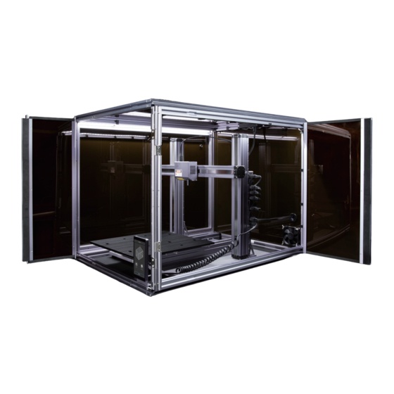
- Page 3 Modular System Snapmaker is not only a 3D printer, but also a powerful machine that you can customize with addons. You can equip your Snapmaker with an enclosure to protect you and your family from laser and contaminants. New addons are coming soon with more exciting features.
- Page 4 CONTENTS Before You Start Enclosure Assembly How to Use...
- Page 5 Before You Start...
- Page 6 Before You Start 1.1 Parts List The Enclosure for Snapmaker A350 is used as a demonstration in this guide. All illustrations are applicable to both Enclosures for Snapmaker A250 and A350 models. | Enclosure QUICK START GUIDE A250 A350 Cable Clip Hose Clamp ×...
- Page 7 Back Panel Side Panel × 1 × 1 Exhaust Fan Touchscreen × 1 Holder × 1 Foot Fixture Hose × 4 Connector × 1 Top Panel × 1 Connecting Cable LED Strip Cable × 1 × 2 Snapmaker Enclosure |...
- Page 8 Ensure anyone who uses this product has read and understood this guide before operation. Failure to do so is likely to result in personal injury, inferior results, or damage to Snapmaker products, for which we assume no liability. This guide is for reference use only, and Snapmaker doesn't in any way makes any warranty, express or implied, or assumes any legal responsibility for the accuracy, completeness, or currency of the information provided.
- Page 9 1.6.2 Detach the Filament Holder ① Detach the filament from 3D Printing Module. See 3.2.2 Load Filament in Quick Start Guide for Snapmaker A350 or A250. ② Detach the Filament Holder from the machine. ③ Detach the Filament Holder Tube and secure it on the other side of the Filament Holder Sheet.
- Page 10 Acrylic Dimensions A350 Enclosure 715 (W) × 672 (H) × 885 (Depth) mm, 19.3 kg A250 Enclosure 619 (W) × 689 (H) × 576 (Depth) mm, 14.2 kg Exhaust Fan 80 (W) × 80 (H) × 20 (D) mm Hose 75 (Diameter) ×...
- Page 11 Enclosure Assembly...
- Page 12 Enclosure Assembly 01 Assemble the bottom rectangular frame. Each beam of the enclosure frame is engraved with its model name, so you can identify the beams by their names. Make sure the 48CA Beams are accurately mounted onto the grooves of the 24 Beams.
- Page 13 02 Assemble the bottom rectangular frame. 48CA BEAM A350-4 × 1 M4 × 28 Hex Socket Short Head × 2 Screw Snapmaker Enclosure |...
- Page 14 Enclosure Assembly 03 Assemble the bottom rectangular frame. 24 BEAM A350-4 × 1 M4 × 28 Hex Socket Short Head × 4 Screw...
- Page 15 04 Attach the Touchscreen Holder. M4 × 20 Hex Socket Head × 2 Screw Touchscreen Holder × 1 Snapmaker Enclosure |...
- Page 16 Enclosure Assembly 05 Attach the 24 Beam A350-3 with Hall Switch to the bottom frame. 180° Step 04 Do not tighten the screws until Step 10. 24 BEAM A350-3 × 1 M4 × 28 Hex Socket Short Head × 2 Screw...
- Page 17 06 Attach all three of the 24 Beam A350-2. M4 × 28 Hex Socket Short Head × 6 Screw Do not tighten the screws until Step 10. 24 BEAM A350-2 × 3 Snapmaker Enclosure |...
- Page 18 Enclosure Assembly 07 Assemble the top rectangular frame. 24 BEAM A350-1 48CA BEAM A350-3 × 1 × 1 M4 × 28 Hex Socket Short Head × 2 Screw...
- Page 19 08 Assemble the top rectangular frame. 48CA BEAM A350-1 × 1 M4 × 28 Hex Socket Short Head × 2 Screw Snapmaker Enclosure |...
- Page 20 Enclosure Assembly 09 Assemble the top rectangular frame. M4 × 28 Hex Socket Short Head × 4 Screw 24 BEAM A350-4 × 1...
- Page 21 Fix the top rectangular frame. 180° Step 09 M4 × 28 Hex Socket Short Head Attach 8 M4 × 28 screws, and × 8 Screw tighten all 16 M4 × 28 screws that are attached in Step 5, 6 and 10. Snapmaker Enclosure |...
- Page 22 Enclosure Assembly 11 Make sure the enclosure frame is properly assembled by checking the features below.
- Page 23 12 Make sure the enclosure frame is properly assembled by checking the features below. Snapmaker Enclosure |...
- Page 24 Enclosure Assembly 13 Assemble the Back-Panel Kit. Back Panel × 1 M4 Wing Nut × 4 Exhaust Fan × 1 Hose Connector × 1 M4 × 35 Hex Socket Head × 4 Screw...
- Page 25 If you have difficulty in aligning the Back Panel's screw holes with those of the frame, slightly loosen the screws that are attached in Step 5,6 and Step 10 and fine-tune the shape of the frame. Snapmaker Enclosure |...
- Page 26 Enclosure Assembly 15 Connect the Hall Switch Cable to either of the Hall Switch Ports of the Enclosure Converter.
- Page 27 16 Connect the LED Strips with the Enclosure Converter using two LED Strip Cables. LED Strip Cable × 2 Snapmaker Enclosure |...
- Page 28 Enclosure Assembly 17 Connect the Exhaust Fan to the Enclosure Converter.
- Page 29 18 Bury the Hall Switch Cable, Exhaust Fan Cable and the right LED Strip Cable into the grooves of the beams. Fix the cables with Cable Clips. Cable Clip × 16 Snapmaker Enclosure |...
- Page 30 Enclosure Assembly 19 Bury the left LED Strip Cable into the groove of the beam. Fix the cable with Cable Clips. Cable Clip × 3...
- Page 31 20 Move the machine to a proper place for subsequent gas emission and enclose it with the frame from above. The provided hose measures 75 mm in diameter and 2 m in length. Snapmaker Enclosure |...
- Page 32 Enclosure Assembly 21 Clamp the Foot Fixtures onto the four feet of the machine; then fix the fixtures onto the Enclosure. Foot Fixture × 4 M4 × 20 Hex Socket Head × 4 Screw...
- Page 33 Connect the Enclosure with the machine. Insert one end of the connecting cable into the Expansion Port of the Converter, and the other to the Addon 3 Port of the Controller. Connecting Cable × 1 Ensure the connectors are inserted in the right direction. Snapmaker Enclosure |...
- Page 34 Enclosure Assembly 23 Attach Folding Door Sliders to the Side Folding Door. Side Folding Door × 1 Circular Magnet × 2 Folding Door Slider × 2 M3 × 10 Hex Socket Head × 4 Screw M3 Hex Nut × 4 Use H2.0 screwdriver bit or H2.0 Hex Key.
- Page 35 24 Mount the two Folding Door Sliders into the slider grooves of the beams. Snapmaker Enclosure |...
- Page 36 Enclosure Assembly 25 Move the Side Folding Door horizontally to the right until it aligns with the frame; then fix the Side Folding Door with screws. M4 × 20 Hex Socket Head × 4 Screw...
- Page 37 26 Connect the Touchscreen to the Controller and place it on the Touchscreen Holder of the Enclosure. Snapmaker Enclosure |...
- Page 38 Enclosure Assembly 27 Attach Folding Door Sliders to the Front Folding Door. Front Folding Door × 1 M3 Hex Nut × 4 Folding Door Slider × 2 Circular Magnet × 2 M3 × 10 Hex Socket Head × 4 Screw Use H2.0 screwdriver bit or H2.0 Hex Key.
- Page 39 28 Mount the two Folding Door Sliders into the slider grooves of the beams. Snapmaker Enclosure |...
- Page 40 Enclosure Assembly 29 Move the Folding Door horizontally to the left until it aligns with the frame; then fix the Folding Door with screws. M4 × 20 Hex Socket Head × 4 Screw...
- Page 41 30 Attach the Side Panel. Snap Bushing × Side Panel × 1 A350: M4 × 12 Hex Socket Round × 12 Head Screw A250: M4 × 12 Hex Socket Round × 10 Head Screw Snapmaker Enclosure |...
- Page 42 Enclosure Assembly 31 Attach the Filament Holder. M4 × 20 Hex Socket Head × 2 Screw...
- Page 43 32 Attach the Top Panel. A350: M4 × 12 Hex Socket Round × 12 Head Screw A250: M4 × 12 Hex Socket Round × 10 Head Screw Top Panel × 1 Snapmaker Enclosure |...
- Page 44 Enclosure Assembly 33 Put the Hose Clamp the hose; then connect the hose to the outer edge of the Hose Connector. Twist the handle of the clamp clockwise to secure the connection. Hose × 1 Hose Clamp × 1...
- Page 45 ① Switch off the power and unplug the DC Power Cable, the connecting cable for the Enclosure and the Touchscreen Cable. ② Detach the Foot Fixtures and move the machine into place. ③ Enclose the machine and fix the Foot Fixtures. Snapmaker Enclosure |...
- Page 46 How to Use...
- Page 47 3.1 Controlling LED Strips and Exhaust Fan Guides & Pictures / Snapmaker Before use, upgrade your firmware to above V1.10.0 from https://snapmaker.com/ product/snapmaker-2/downloads. When the machine is not under a 3D printing, laser or CNC process, the LED Strips and the Exhaust Fan can be controlled by entering Home >...
- Page 48 How to Use When the machine is working, you can swipe left on the Touchscreen to control the LED Strips and the Exhaust Fan.
- Page 49 3.2 Switching Functions Guides & Pictures / Snapmaker To change the toolheads and the platforms when the machine is enclosed, follow the steps below. Use the H2.5 bit of the screwdriver. 3.2.1 Fold and open two doors. 3.2.2 Enter Home > Control > Jog Mode to move the toolhead and platform to positions that are convenient for detaching.
- Page 50 How to Use 3.2.3 Switch off the machine, unplug the Toolhead Cable; then detach the toolhead and platform. If the machine is currently equipped with 3D printing components, make sure to unplug the Heated Bed Cable before detaching the Heated Bed. To avoid injury, remove the CNC Bit before detaching the CNC Module from the machine.
- Page 51 Heated Bed Cable. Do not plug or unplug any cables when the machine is turned on. Check if all the cables are properly connected before switching on the machine. Wrong connection may cause serious damage or injury. Toolhead X Axis Y Axes Z Axes Enclosure Power Module Touchscreen Snapmaker Enclosure |...
- Page 52 When the machine is connected to a computer with the USB Cable, and is operating a laser process through Snapmaker Luban, Door Detection is not available. In this case, do not open the Enclosure door, otherwise the laser will stop emitting, which leads to failure of the engraving job.
- Page 53 For Quick Start Guides and User Manuals: https://support.snapmaker.com/hc/en-us/ For general information or technical support: support@snapmaker.com. For sales inquiries: sales@snapmaker.com. For product purchases: https://shop.snapmaker.com. Share anything you want in our forum: https://forum.snapmaker.com. Share anything you want via the following channels: Snapmaker Enclosure |...
- Page 54 Y.3.B.A.0059-01 V1.1.0...
Need help?
Do you have a question about the A250 and is the answer not in the manual?
Questions and answers