
Related Manuals for Lowrance X47


Summary of Contents for Lowrance X47
- Page 1 Pub. 988-0105-941 www.lowrance.com X47 and X47EX Fish-finding & Depth Sounding Sonars Installation and Operation Instructions...
- Page 2 Lowrance Electronics, Inc. Marine-Tex is a trademark of Illinois Tool Works Inc. Lowrance Electronics may find it necessary to change or end our policies, regulations, and special offers at any time. We reserve the right to do so without notice. All features and specifications subject to change without notice.
-
Page 3: Table Of Contents
Introduction ... 1 Capabilities and Specifications: X47 and X47EX... 1 Installation Preparations ... 2 Transducer Installation... 3 Recommended Tools and Supplies ... 3 Selecting a Transducer Location ... 4 Shoot-Thru-Hull vs. Transom Mounting ... 5 Transom Transducer Assembly and Mounting ... 5 Trolling Motor Bracket Installation... - Page 4 Display Contrast ... 37 Depth Units of Measure ... 37 Preset Unit (Reset All Options)... 37 System Info ... 37 Simulator... 38 Digital Data Size for Depth and Temperature ... 38 Troubleshooting ... 39 Warranty and Service Information... 45...
-
Page 5: Introduction
Capabilities and Specifications: X47 and X47EX Case size: ... X47: 5.8" H x 4.3" W x 2.5" D (14.7 cm H x Display:... High-contrast Film SuperTwist LCD. Resolution:... 168 pixels (vert.) x 132 pixels (horiz.) Backlighting:... -
Page 6: Installation Preparations
Customer Service Department; phone numbers are inside the manual's back cover. Installation Preparations You can install the sonar system in some other order if you prefer, but we recommend this installation sequence: Caution: You should read over this entire installation section before drilling any holes in your vessel! 1. -
Page 7: Transducer Installation
3. Determine the location of your battery or other power connection, along with the power cable route. 4. Install the transducer and route the transducer cable to the sonar unit. 5. Install the power cable and route it to the sonar unit. -
Page 8: Selecting A Transducer Location
If the transducer is not placed in a smooth flow of water, interference caused by bubbles and turbulence will show on the sonar's display in the form of random lines or dots whenever the boat is moving. -
Page 9: Shoot-Thru-Hull Vs. Transom Mounting
usually give you the best combination of smooth water flow and protection from bangs and bumps. Transducer centerline Align transducer centerline with hull bottom. However, there are times when you may need to adjust the transducer slightly higher or lower. (The slots in the mounting brackets allow you to loosen the screws and slide the transducer up or down.) If you frequently lose bottom signal lock while running at high speed, the transducer may be coming out of the water as you cross waves or... - Page 10 parts first, place the transducer's bracket against the transom and see if you can move the transducer so that it's parallel with the ground. 1. Assembling the bracket. Press the two small plastic ratchets into the sides of the metal bracket as shown in the following illustration. Notice there are letters molded into each ratchet.
- Page 11 3. Assembling the transducer. position for the ratchets, assemble the transducer as shown in the following figure. Don't tighten the lock nut at this time. Assemble transducer and bracket. 4. Drilling mounting holes. Hold the transducer and bracket assembly against the transom. The transducer should be roughly parallel to the ground.
- Page 12 Align transducer centerline with hull bottom and attach to transom. 6. Route the transducer cable through or over the transom to the sonar unit. Make sure to leave some slack in the cable at the transducer. If possible, route the transducer cable away from other wiring on the boat.
-
Page 13: Trolling Motor Bracket Installation
(not included) to attach the transducer cable to the trolling motor shaft. Make sure there is enough slack in the cable for the motor to turn freely. Route the cable to the sonar unit and the transducer is ready for use. -
Page 14: Transducer Orientation And Fish Arches
The transducer installation inside a fiberglass hull must be in an area that does not have air bubbles in the resin or separated fiberglass layers. The sonar signal must pass through solid fiberglass. A successful transducer installation can be made on hulls with flotation materials (such as plywood, balsa wood or foam) between layers of fiberglass if the material is removed from the chosen area. - Page 15 ASP.) Don't touch the controls once they've been set. Next, take the transducer out of the water and place it in the water in the sump of the boat. Observe the sonar signal to see if there is a noticeable decrease in sensitivity. The second bottom signal may disappear and the bottom signal may decrease in intensity.
- Page 16 The face of the transducer should be parallel with the hull, with a minimum amount of epoxy between the hull and transducer. After the epoxy dries, route the cable to the sonar unit. Epoxy transducer to hull. Transducer location...
-
Page 17: Power And Cable Connections
To unit Power and transducer connections for the X47 and X47EX sonar units (direct battery connection shown). If possible, keep the power cable away from other boat wiring, especially the engine's wires. -
Page 18: Mounting The Sonar Unit: In-Dash Or Bracket
You can install the sonar unit on the top of a dash with the supplied bracket. It can also be installed in the dash with an optional dash- mounting kit (FM-5 mount kit for X47EX, FM-6 mount kit for X47). In-Dash Installation For the X47EX The following figure shows dimensions for in-dash mounting an X47EX. - Page 19 For the X47 The X47 can be mounted in-dash using the removable scaled template inside the back cover of this manual (page 43). The FM-6 mount kit includes the necessary materials, but the instructions only appear here in this manual.
-
Page 20: Bracket Installation
In-dash mounting template for X47. NOTE: This figure is not printed to scale. See the back of this manual for a scaled template copy you can tear out and use. - Page 21 173.9 [6.85] 137.9 [5.43] Millimeter [Inch] Front view (left) and side view (right) showing dimensions of X47EX when mounted on gimbal bracket. Drill a 5/8" (15.9 mm) hole in the dash for the power/transducer cable. The best location for this hole is immediately under the gimbal bracket location.
- Page 22 [4.23] 76.9 [3.03] Front view (left) and side view (right) showing dimensions of the X47 when mounted on quick release bracket. If you wish, you can fill in the hole around the cable with a good marine caulking compound. (Some marine dealers stock cable hole covers to conceal the opening.) No matter what type of installation you prefer, be...
- Page 23 Screw hole Power/transducer cable X47 quick release mounting bracket. Slots in the base allow routing the cable from beneath the mount. Attach the unit to the bracket by first connecting the power/transducer cable.
-
Page 24: Portable Sonar Installation
The power pack and portable or floating transducers expand the uses for your sonar. You can use your X47 sonar unit on your boat or take it to the dock, on a float tube, on an ice fishing trip or use it as a second sonar in a friend's boat. - Page 25 "D" cell battery Install batteries in power case battery adapter. PPP-13 shown. Turn the sonar unit on. If it doesn't work, make sure the battery terminals are making good contact against the battery contacts. Also...
- Page 26 In cold weather the efficiency of dry cell batteries drops with the temperature. We find it a good idea to have the sonar unit good and warm along with the batteries before we leave home.
- Page 27 Moisten the cup, then press it onto the hull as firmly as possible. Tie the nylon cord to the boat and route the transducer cable to the sonar unit. Your portable sonar is now ready for use.
-
Page 28: Operation
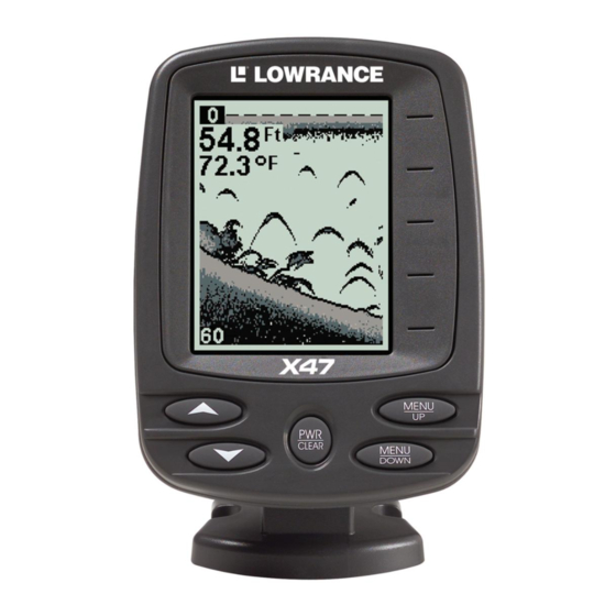
The unit sounds a tone when you press any key. This tells you the unit has accepted a command. Numbers in the following photos correspond to key explanations in the following pages: X47 and X47EX Sonars, front view, each 1. PWR/CLEAR (power and clear) This key appears in the manual text simply as turn the unit on and off. -
Page 29: Memory
When the sonar unit is first turned on and the backlight menu disappears, the display screen shows the Full Chart Page, or mode. The Fish I.D. fish symbol feature is off. The depth range shows on the... -
Page 30: Chart Scroll (Stopping And Starting)
In the following figure, the screen shows a depth range from 0 to 80 feet and the bottom depth is 37.9 feet, shown by the digital sonar. The water temperature is 34.5° F. Digital depth... -
Page 31: Full Chart
The bottom signal scrolls across the screen from right to left. The line at the top of the screen represents the surface. The bottom depth (as determined by the digital sonar) shows in the upper left corner. Digital depth... -
Page 32: Zoom
to select DOWN ARROW menu. Use the arrow keys to select a desired depth range. ANGE When you're finished, press This unit has the following depth ranges: 10, 20, 40, 80, 160, 320 and 640 feet. Range Size menu with manual depth range set to 40 feet. This in effect "zooms"... -
Page 33: Sensitivity
When you Zoom while the unit is in manual depth Range Zoom mode, you can select one of 13 pre-set Zoom Sizes. This lets you enlarge some other particular segment of the water column. To do this, first make sure the depth Range Zoom is in manual mode. (See previous instructions for Depth Range Zoom.) Next, press the key until the MENU... - Page 34 In your unit, auto mode will let you increase sensitivity to 100 percent, but the unit will limit your minimum setting. This prevents you from turning sensitivity down too low to allow automatic bottom tracking. When you change the setting with auto turned on, the unit will continue to track the bottom and make minor adjustments to the sensitivity level, with a bias toward the setting you selected.
-
Page 35: Grayline
Since Grayline shows the difference between strong and weak signals, adjusting the sensitivity may also require a different Grayline level. The level chosen by the sonar unit at power on is usually adequate for most conditions. Experiment with your unit to find the Grayline setting that's best for you. -
Page 36: Down Arrow
Thin or no Grayline At left, little Grayline indicates a soft bottom, probably sand or mud. At right, the wider Grayline indicates a harder, rocky bottom. Press UP ARROW decrease it. The percentage of Grayline in use shows in this menu. Echoes scrolling onto the screen will also show the effects of the Grayline change. -
Page 37: Fishtrack
Fish I.D. is an easier way for a sonar novice to recognize a fishy signal return when he sees it. However, locating fish by symbol only has some limitations. Your sonar unit's microcomputer is sophisticated, but it can be fooled. It can't distinguish between fish and other suspended objects such as trotlines, turtles, submerged floats, air bubbles, etc. -
Page 38: Chart Scroll Speed
50 percent. When you are stationary and a fish swims through the sonar signal cone, the image appears on the screen as a long line instead of a fish arch. Reducing the chart speed may result in a shorter line that more closely resembles a regular fish return. -
Page 39: Alarms
ASP is an effective tool in combating noise. In sonar terms, noise is any undesired signal. It is caused by electrical and mechanical sources such as bilge pumps, engine ignition systems and wiring, air bubbles passing over the face of the transducer, even vibration from the engine. In all cases, noise can produce unwanted marks on the display. -
Page 40: Shallow Alarm
bottom goes shallower than the alarm's setting. The deep alarm sounds a tone when the bottom goes deeper than its setting. Both alarms adjust the same way, although through different menus. Shallow Alarm To set the shallow alarm depth, press repeatedly until Press UP ARROW... -
Page 41: Display Contrast
DISPLAY CONTRAST The unit’s display contrast is adjustable to suit different lighting conditions. This will help you see the screen from different angles or at various times of the day. The default setting is min (minimum) percent. To adjust the contrast, press menu appears. -
Page 42: Simulator
SIMULATOR This unit has a built-in simulator that shows a simulated bottom signal with fish signals. This lets you practice with the unit as if you were on the water; all features and functions of the unit are usable. A message appears occasionally to remind you that the simulator is on. -
Page 43: Troubleshooting
Rerouting the power and transducer cables away from other electrical wiring on the boat may help. Route the sonar unit's power cable directly to the battery instead of through a fuse block or ignition switch 2. - Page 44 This can cause the unit to eliminate weaker signals such as fish or even structure from the display. 3. The water may be deeper than the sonar's ability to find the bottom. If the sonar can't find the bottom signal while it's in the automatic mode, the digital sonar display will flash continuously.
- Page 45 With the boat at rest in the water, the first thing you should do is turn all electrical equipment on the boat off. Make sure the engine is also off. Turn your sonar on, then turn off Noise Reject [also known as the ASP feature (Advanced Signal Processing)].
- Page 46 Notes If the dash mount template on page 43 has been removed from this manual, a free replacement manual containing the template can be downloaded from our web site, www.lowrance.com.
- Page 47 The vertical line and the horizontal line should each be 2 inches long (50.8 mm.) Cut along this line In-dash mounting template for X47. NOTE: This figure is printed to scale. For use with FM-6 mount kit.
- Page 48 Notes...
-
Page 49: Warranty And Service Information
LOWRANCE ELECTRONICS FULL ONE-YEAR WARRANTY "We," "our," or "us" refers to LOWRANCE ELECTRONICS, INC., the manufacturer of this product. "You" or "your" refers to the first person who purchases this product as a consumer item for personal, family or household use. -
Page 50: How To Obtain Service
…in the USA: We back your investment in quality products with quick, expert service and genuine Lowrance parts. If you're in the United States and you have technical, return or repair questions, please contact the Factory Customer Service Department. Before any product can be returned, you must call customer service to determine if a return is necessary. -
Page 51: Accessory Ordering Information For All Countries
Accessory Ordering Information for all countries To order Lowrance GPS accessories such as computer cables or MMC cards, please contact: 1) Your local marine dealer or consumer electronics store. Most quality dealers that handle marine electronic equipment or other consumer electronics should be able to assist you with these items. -
Page 52: Visit Our Website
Visit our web site: Lowrance Pub. 988-0105-941 © Copyright 2002 All Rights Reserved Printed in USA 111902 Lowrance Electronics, Inc.
Need help?
Do you have a question about the X47 and is the answer not in the manual?
Questions and answers