Table of Contents
Advertisement
Advertisement
Table of Contents

Related Manuals for Lowrance X-29


Summary of Contents for Lowrance X-29
- Page 1 X-29, X-39 X-49 INSTALLATION AND OPERATION INSTRUCTIONS...
-
Page 2: Table Of Contents
ASP (Advanced Signal Processing) ... 29 SIMULATOR ... 29 TROUBLESHOOTING ... 30 WARRANTY ... 33 Copyright © 2000, Lowrance Electronics, Inc. All features and specifications in this manual are subject to change without notice. All screens in this manual are simulated. -
Page 3: Introduction
INTRODUCTION Thank you for purchasing a Lowrance sonar. Your sonar unit is a high quality unit designed for both professional and novice fishermen. All of our sonars have an automatic feature that finds and displays the bottom, fish, structure, and more! All you have to do is press the on key. However, if you wish to fine tune the unit, all you have to do is press the menu key. -
Page 4: Transducer Installation
Transducer Installation Some of the models covered by this manual have a transom-mount transducer included. The following are installation instructions for this transducer. The “kick-up” mounting bracket helps prevent damage if the transducer strikes an object while the boat is moving. If the transducer does “kick- up”, the bracket can easily be pushed back in place without tools. -
Page 5: Shoot-Thru-Hull Vs. Transom Mounting
Shoot-thru-hull v.s. Transom Mounting Typically, shoot-thru-hull installations give excellent high speed opera- tion and good to excellent depth capability. There is no possibility of damage from floating objects. It can't be knocked off when docking or loading on the trailer. However, the shoot-thru-hull installation does have its drawbacks. - Page 6 2. Slide the transducer between the two ratchets. Temporally slide the bolt though the transducer assembly and hold it against the transom. Looking at the transducer from the side, check to see if it will adjust so that its face is parallel to the ground. If it does, then the “A” position is correct for your hull.
- Page 7 CAUTION! CLAMP THE TRANSDUCER CABLE TO TRANSOM NEAR THE TRANSDUCER. THIS WILL HELP PREVENT THE TRANSDUCER FROM ENTERING THE BOAT IF IT IS KNOCKED OFF AT HIGH SPEED. GOOD LOCATION POOR LOCATION POOR ANGLE GOOD LOCATION 4. Hold the transducer and bracket assembly against the transom. The transducer should be roughly parallel to the ground.
- Page 8 5. Remove the transducer from the bracket and re-assemble it with the cable passing through the bracket over the bolt as shown above. At- tach the transducer to the transom. Slide the transducer up or down until it’s aligned properly on the transom as shown above. Tighten the bracket’s mounting screws.
- Page 9 SHOOT-THRU-HULL The transducer installation inside a fiberglass hull must be in an area that does not have air bubbles in the resin or separated fiberglass layers. The sonar signal must pass through solid fiberglass. A success- ful transducer installation can be made on hulls with flotation materials (such as plywood, balsa wood, or foam) between layers of fiberglass if the material is removed from the chosen area.
-
Page 10: Shoot-Thru-Hull Installation
TRANSDUCER LOCATION TRANSDUCER LOCATION (HIGH SPEED) (TROLLING SPEED) Shoot-thru-hull Installation 1. Make certain the area is clean, dry, and free of oil or grease, then sand both the inside surface of the hull and the face of the transducer with 100 grit sandpaper. The surface of the hull must be flat so the entire transducer face is in contact with the hull prior to bonding. - Page 11 hull. Place the transducer into the epoxy, twisting and turning it to force any air bubbles out from under the transducer face. The face of the transducer should be parallel with the hull, with a minimum amount of epoxy between the hull and transducer. After the epoxy dries, route the cable to the sonar unit.
-
Page 12: Power Connections
POWER CONNECTIONS - All units This unit works from a 12 volt DC system only. For the best results, run the power cable directly to the boat’s battery. Keep the power cable away from other boat wiring, especially the engine’s wires. This will give the best isolation from electrical noise. -
Page 13: Bracket Installation
Bracket Installation You can install the sonar unit on the top of a dash or from an overhead with the supplied bracket. It can also be installed in the dash with an optional IDA-3 mounting kit. If you use the supplied bracket, you may be interested in the optional GBSA-1 swivel bracket kit. -
Page 14: Speed/Temperature Sensors
SPEED/TEMPERATURE SENSORS The X-39 and X-49 can use up to three optional temperature sensors which can monitor surface water, live well, air, and virtually any other tempera- ture. You do need to be careful when purchasing the temperature sensors, however. Each temperature sensor has its own "address". The sensors are labeled "Water", "T-2"... -
Page 15: Sensor Chart
(Note: Do not use these sensors in any other combination.) ST-TBK = 1 speed sensor and 1 temperature display ST-T BK + TS-2BK = 2 temp sensors and one speed sensor ST-TBK + TS-2BK + TS-3BK = 3 temp sensors and one speed sensor TS-1BK = 1 temperature sensor TS-12BK = 2 temperature sensors TS-1BK + TS-2BK = 2 temperature sensors... - Page 16 TS-12 BK Sensor Chart (Note: Do not use these sensors in any other combina- tion.) TS-3 BK Three Temperature Sensors (Water, T-2, and T-3) X-39 or X-49 POWER CABLE ST-TBK TS-2 BK TS-3 BK Three Temperature Sensors plus Speed (Water, T-2, T-3, and Speed) X-39 or X-49 POWER CABLE...
-
Page 17: Keyboard Basics
KEYBOARD BASICS The unit sounds a tone when you press any key. This tells you the unit has accepted a command. PWR/CLEAR Use this key to turn the unit on. It also clears menu selections and the menus from the screen. -
Page 18: Operation
OPERATION MENUS This unit uses menus to guide you through the unit’s functions and features. The menu key accesses these features, allowing you to cus- tomize the unit to your particular needs and water conditions. All you have to do to leave one menu and enter another is press the menu key repeatedly. -
Page 19: Zoom
After you select the desired range, press the PWR key to clear the display. If you wait a few seconds, it will automatically clear. This unit has the following ranges: 10, 20, 40, 60, 120, 240, 480, and 900 feet. 5, 10, 20, 40, 60, 100, 200, and 300 meters. - Page 20 This means the unit is tracking the bottom in a zoom window, always keeping it on the display. Press the up arrow key to decrease the zoom size, press the down arrow key to increase the zoom size. When the unit is switched into the zoom mode, the letters “ZM”...
-
Page 21: Upper/Lower Limits
RANGE - Upper and Lower Limits You can change the upper and lower range limits when the unit is in the manual mode. This lets you "zoom" in on segments of the water as small as 10 feet. In other words, you can set the upper limit to 25 feet and the lower limit to 35 feet, regardless of the bottom depth. -
Page 22: Sensitivity
SENSITIVITY The sensitivity menu lets you control the unit’s ability to pick up echoes. A low sensitivity level excludes much of the bottom information, fish signals, and other detail. High sensitivity settings lets you see features, but it can also clutter the screen with noise and other unwanted signals. Typically, the best sensitivity level shows a good, solid bottom signal with grayline. -
Page 23: Fish Id
® Grayline is adjustable. Since it shows the difference between strong and weak echoes, changing the level may require a different sensitivity setting. To change the Grayline level, first press the MENU key until the Grayline menu appears. Now press the up arrow key to increase the level, the down arrow to decrease it. -
Page 24: Fish Track
The Fish ID feature can’t be used when the unit is in the manual mode. If you turn the automatic feature off, the Fish ID feature will automatically be turned off, also. FISH TRACK™ This unit automatically displays the depth of a target when the Fish ID feature places a fish symbol on the screen as shown below. -
Page 25: Display Mode
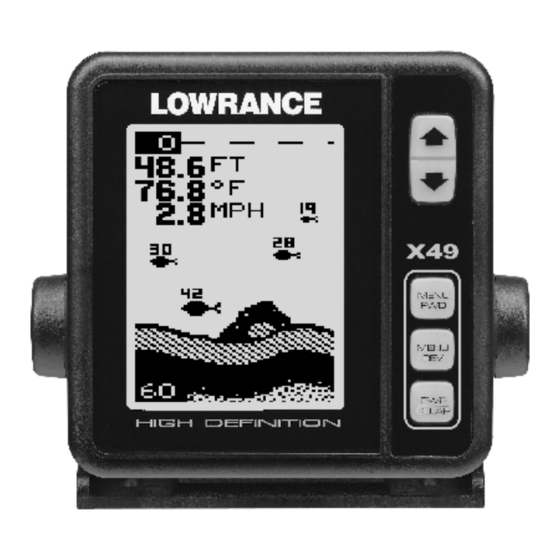
DISPLAY MODE The X-29 has three different screen modes. The X-39 and X-49 has eight modes. To change modes, press the MENU key until the “DISP MODE” (Display Mode) menu appears. Then press the up or down arrow keys until the desired mode number appears. - Page 26 X-39 and X-49 ONLY CHT 1 (Chart #1) This is the default mode used when the unit is first turned on. It has the following features: 1. Automatic On 2. Fish ID Feature On 3. Digital Depth Display On CHT 2 (Chart #2) Same as Chart-1, but with water tempera- ture added.
- Page 27 X-39 and X-49 ONLY (cont.) CHT 4 (Chart #4) Same as Chart-1, but with water tempera- ture and speed added. CHT 5 (Chart #5) This is the High Speed Scroll mode. It shifts the chart speed into high gear, scrolling ech- oes at a high rate.
-
Page 28: Temperature Probe Select
X-39 and X-49 ONLY (cont.) DIG 2 (Digital #2) Digital depth, water temperature, speed, and distance log (odometer) show on this page. To reset the log, turn the unit off and back on again. DIG 3 (Digital #3) Digital depth, water temperature, T-2 tem- perature, and T-3 temperature all show on this screen. -
Page 29: Depth Alarms
ALARMS FISH ALARM The Fish Alarm sounds a tone when a fish symbol appears on the screen. To use the fish alarm, press the menu key until the “FISH ALARM” menu appears on the screen. Now press the up arrow key to turn the alarm on. Repeat the above steps to turn the fish alarm off. -
Page 30: Light
Deep Alarm The deep alarm adjusts the same as the shallow alarm. Use the “DEEP ALARM” menu to adjust the deep alarm. When the bottom signal goes deeper than the setting, an alarm tone sounds. LIGHTS The display is backlighted for night use. To turn the backlights on or off, press the menu key repeatedly until the BACK LIGHT menu appears. -
Page 31: Asp (Advanced Signal Processing)
reach the maximum or minimum level, a tone sounds alerting you to the limits. The menu will clear automatically after a few seconds or you can press the PWR key to clear the screen. ASP (Advanced Signal Processing) ASP is a program embedded in the computer that is specifically designed to eliminate noise. -
Page 32: Troubleshooting
TROUBLESHOOTING - IMPORTANT INFORMATION! If your unit is not working, or if you need technical help, please use the following troubleshooting section before contacting the factory customer service department. It may save you the trouble of returning your unit. Unit won’t turn on: 1. - Page 33 the digital will flash continuously. It may change the range to limits far greater than the water you are in. If this happens, place the unit in the manual mode, then change the range to a realistic one, (for example, 0- 100 feet) and increase the sensitivity.
-
Page 34: Electrical Noise
ELECTRICAL NOISE A major cause of sonar problems is electrical noise. This usually appears on the sonar’s display as random patterns of dots or lines. In severe cases, it can completely cover the screen with black dots, or cause the unit operate erratically, or not at all. -
Page 35: Warranty
LOWRANCE ELECTRONICS FULL ONE-YEAR WARRANTY “We", “our”, or “us” refers to LOWRANCE ELECTRONICS, INC., the manufacturer of this product. “You” or “your” refers to the first person who purchases this product as a consumer item for personal, family, or household use. - Page 36 Notes:...
-
Page 37: How To Obtain Service
We back your investment in quality products with quick, expert service and genuine Eagle replacement parts. If you need service or repairs, contact the Lowrance Factory Customer Service Department at the toll-free number listed below. A technician may be able to solve the problem and save you the inconvenience of returning your unit. - Page 38 Remember, non-warranty repairs are subject to Lowrance's published flat- rate charges and 180-day warranty. Lowrance Electronics may find it necessary to change or end our shipping policies, regulations, and special offers at any time. We reserve the right to do so without notice.
Need help?
Do you have a question about the X-29 and is the answer not in the manual?
Questions and answers
Cherche Sonde x49
The Lowrance X-29 sonar is a high-quality fishfinder designed for both professional and novice fishermen. It features automatic operation, a digital depth display, and various display modes. It can be installed using a bracket or mounted in-dash with optional kits. The unit includes features like Fish ID, Fish Track™, chart speed adjustment, alarms, and support for temperature and speed sensors. It requires a 12-volt power source with a 3-amp fuse for protection.
This answer is automatically generated