Advertisement
Quick Links
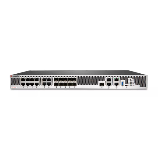
PA-1400 Series
1
Before You Begin
Use this document to install and begin setting up your Palo Alto Networks firewall. Refer to the Firewall Hardware Reference at
https://docs.paloaltonetworks.com/hardware
for safety information, specifications, and more detailed procedures for installing
the firewall.
◼
Verify that the installation site has adequate air circulation and AC power.
◼
Have a #1 and #2 Phillips-head torque driver available. Use the #1 Phillips-head bit to attach the rack-mount brackets to the firewall and use
the #2 bit to secure the rack-mount brackets to the equipment rack posts.
◼
Unpack the equipment and verify that you received the following items:
Qty
Description
1
PA-1400 Series next-generation firewall.
1
AC power cord
1
Standard Type-A USB to micro USB console cable.
1
Standard RJ-45 CAT6 Ethernet cable for management (MGT) port access.
1
Velcro.
1
Desiccant.
2
1RU mounting ears (left and right).
2
Rear support brackets.
2
Adjustable mounting brackets (left and right)
13
#6-32 x 5/16" rack-mount screws.
9
#10-32 x 3/4" rack-mount screws.
9
#12-24 x 1/2" rack-mount screws.
8
#10-32 nut cages.
1
End User License Agreement (EULA).
1
China RoHS declaration.
2
Rack Mount the Firewall
The PA-1400 Series firewall ships with a rack mount kit for installation in a four-post 19" equipment rack.
Ensure that the equipment rack is properly anchored so it can support the weight of the installed equipment.
1
Attach one rack-mount bracket to each side of the firewall using four #6-32 x 5/16" screws for each bracket as shown in Figure 1 and torque to
9 in-lbs.
2
Attach one side rack-mount rail to each side of the firewall using two #6-32 x 5/16" screws for each bracket and torque to 9 in-lbs. See Figure
2. The side rack-mount rail screws ship with the rack kit.
3
With help from another person, hold the firewall in the rack and secure the rack-mount brackets to the front rack posts using two screws for
each bracket, as shown in Figure 3. Use the appropriate screws (#10-32 x 3/4" or #12-24 x 1/2") for your rack and torque to 25 in-lbs. Use cage
nuts (not provided) to secure the screws if the rack has square holes.
4
Slide one back rack-mount bracket into each of the two previously installed side rack-mount rails and secure the brackets to the back rack
posts using the appropriate screws for your rack (#10-32 x 3/4" or #12-24 x 1/2") and torque to 25 in-lbs. See Figure 4.
Figure 1
docs.paloaltonetworks.com
Figure 2
Page 1 of 2
Figure 3
3
Power on the Firewall
The PA-1400 Series firewalls ship with one AC power supply but can make use of a second (purchased separately) for power
redundancy.
If you are booting the firewall in non-ZTP mode (Standard mode), follow the instructions in Step 4: Connect to the Management
Interface before proceeding to power on the firewall.
1
Remove the nut and star washer from the ground stud on the back of the firewall as shown
in Figure 5.
2
Crimp a 14AWG ground cable to a ring lug (cable and lug not included) and then attach the
ring lug to the ground stud on the firewall.Replace the star washers and nuts and torque to
25 in-lbs. Connect the other end of the cable to earth ground.
3
Connect the AC power cord to the power input on the back of the firewall.
4
Secure the power cord to the power supply using the provided cord retainer.
5
Connect the other end of the power cord to an AC power source. After the power supply is
connected, the power supply powers on, the input and output LEDs on the power supply
turn green, and the PWR LED and the power supply LED (PWR 1 or PWR 2) on the front of
the firewall turns green.
Connect the second power cord (optional) through a different circuit breaker to provide power redundancy and to allow for electrical
circuit maintenance.
Quick Start Guide
Figure 4
Figure 5
Advertisement

Related Manuals for PaloAlto Networks PA-1400 Series


Summary of Contents for PaloAlto Networks PA-1400 Series
- Page 1 China RoHS declaration. Rack Mount the Firewall The PA-1400 Series firewalls ship with one AC power supply but can make use of a second (purchased separately) for power redundancy. The PA-1400 Series firewall ships with a rack mount kit for installation in a four-post 19” equipment rack.
- Page 2 PA-1400 SERIES QUICK START GUIDE (CONTINUED) Connect to the Management Interface If you have already booted up the firewall and selected the wrong mode, you must perform a factory reset or private-data-reset before continuing. For information on how to reset the firewall to its factory default settings, see the PAN-OS Administrator’s Guide.
Need help?
Do you have a question about the PA-1400 Series and is the answer not in the manual?
Questions and answers