Table of Contents
Advertisement
Available languages
Available languages
Quick Links
OPERATOR'S MANUAL
Manual del operador
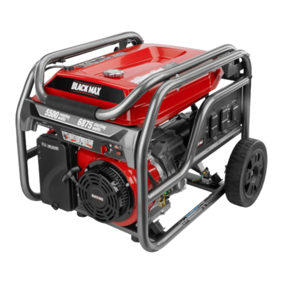
5,500 WATT GENERATOR
Generador de 5 500 W
BM905511
NEUTRAL BONDED TO FRAME
PUNTO NEUTRO CONECTADO AL MARCO
TABLE OF CONTENTS
Important Safety Instructions ...............................................3-4
Specific Safety Rules .............................................................. 4
Symbols ...............................................................................5-7
Electrical ..............................................................................8-9
Features ................................................................................ 10
Assembly .........................................................................11-12
Operation .........................................................................12-15
Maintenance ....................................................................15-18
Troubleshooting .................................................................... 19
Warranty ...........................................................................20-21
Parts Ordering / Service ...........................................Back Page
WARNING:
To reduce the risk of injury, the user must
read and understand the operator's manual before using this
product.
SAVE THIS MANUAL FOR
FUTURE REFERENCE
R
Do not use E15 or E85 fuel in
this product. It is a violation of
federal law and will damage
the unit and void your warranty. Only use unleaded gasoline
containing up to 10% ethanol.
No utilice combustibles E15 o E85 con este producto. Esto
constituye una violación a la ley federal, dañará la unidad
y anulará la garantía. Use únicamente gasolina sin plomo
con un contenido de hasta 10 % de etanol.
Instrucciones de seguridad importantes .............................. 3-4
Reglas de seguridad específicas .............................................4
Símbolos .............................................................................. 5-7
Aspectos eléctricos .............................................................. 8-9
Características .......................................................................10
Armado ............................................................................. 11-12
Funcionamiento ................................................................ 12-15
Mantenimiento .................................................................. 15-18
Corrección de problemas .......................................................19
Garantía ............................................................................ 20-21
Pedidos de piezas / servicio ...............................Pág. posterior
usuario debe leer y comprender el manual del operador antes
de usar este producto.
CUSTOMER SERVICE
1-800-726-5760
To register your Black Max product,
please visit:
http://register.blackmaxtools.com/
Mexico SERVICIO AL CLIENTE
01 800 843 1111
Para registrar su producto de
BlackMax, por favor visita:
http://register.blackmaxtools.com/
NOTICE
ÍNDICE DE CONTENIDO
Para reducir el riesgo de lesiones, el
GUARDE ESTE MANUAL
PARA FUTURAS CONSULTAS
AVISO
Advertisement
Table of Contents

Related Manuals for Black Max BM905511


Summary of Contents for Black Max BM905511
-
Page 1: Table Of Contents
CUSTOMER SERVICE 1-800-726-5760 To register your Black Max product, please visit: http://register.blackmaxtools.com/ OPERATOR’S MANUAL Mexico SERVICIO AL CLIENTE Manual del operador 01 800 843 1111 5,500 WATT GENERATOR Para registrar su producto de BlackMax, por favor visita: Generador de 5 500 W http://register.blackmaxtools.com/... - Page 2 See this fold-out section for all of the figures referenced in the operator’s manual. Consulte esta sección desplegable para ver todas las figuras a las que se hace referencia en el manual del operador. Fig. 1 Fig. 2 A - Reset button (botón de reajuste) B - Test button (botón de prueba) A - Handle release pin (conjunto de pasador de G - Oil drain plug (perno de drenaje de aceite)
- Page 3 Fig. 3 Fig. 4 Fig. 6 Fig. 8 A - Socket wrench (llave de casquillo) B - Adjustable wrench (llave ajustable) A - Hitch pin (pasador del enganche) Fig. 5 B - Washer (arandela) C - Wheel (rueda) D - Axle (eje) E - U-bracket (soporte en “U”) A - Lanyard (correa) Fig.
- Page 4 Fig. 9 Fig. 12 Fig. 15 Fig. 16 A - Oil cap/dipstick (tapa de relleno de aceite / A - Move choke lever left to start (desplace varilla medidora de aceite) izquierda la palanca del anegador para B - Oil fill hole (agujero de llenado de aceite) arrancar) B - Move choke lever right to run (desplace Fig.
- Page 5 Fig. 18 Fig. 20 Fig. 22 A - Spark plug (bujía) B - Spark plug cap (tapa de la bujía) Fig. 19 A - Fuel valve (válvula de combustible) B - Hose barb (conector de manguera dentada) C - Fuel line (conducto de combustible) A - Carburetor drain screw (tornillo de drenaje del carburador) Fig.
- Page 6 To register your Black Max product, please visit: www.blackmaxtools.com LOCATE GENERATOR AT LEAST 20 FT.* AWAY TO REDUCE THE RISK OF CARBON MONOXIDE GETTING INSIDE THE HOME * Minimum distance as recommended by U.S. Department of Health and Human Services Centers for Disease Control and Prevention (www.cdc.gov/co). Your specific home and/or wind conditions may require additional distance.
-
Page 7: Important Safety Instructions
IMPORTANT SAFETY INSTRUCTIONS Do not start or operate the engine in a confined space, building, near open windows, or in other unventilated DANGER: space where dangerous carbon monoxide fumes can Carbon Monoxide. Using a generator indoors CAN KILL collect. Carbon monoxide, a colorless, odorless, and YOU IN MINUTES. -
Page 8: Specific Safety Rules
IMPORTANT SAFETY INSTRUCTIONS Use only recommended or equivalent replacement parts Maintain the unit per maintenance instructions in this and accessories and follow instructions in the Mainte- Operator’s Manual. nance section of this manual. Use of any other parts or Inspect the unit before each use for loose fasteners, fuel failure to follow maintenance instructions may create a leaks, etc. -
Page 9: Symbols
SYMBOLS The following signal words and meanings are intended to explain the levels of risk associated with this product. SYMBOL SIGNAL MEANING Indicates a hazardous situation, which, if not avoided, will result in death or DANGER: serious injury. Indicates a hazardous situation, which, if not avoided, could result in death or WARNING: serious injury. - Page 10 SYMBOLS Some of the following symbols may be used on this product. Please study them and learn their meaning. Proper interpretation of these symbols will allow you to operate the product better and safer. SYMBOL NAME DESIGNATION/EXPLANATION Amperes Current Hertz Frequency (cycles per second) Watt Power...
- Page 11 SYMBOLS FUEL WARNING No smoking when filling with gasoline. Do not overfill. Full level is 1 in. below the top of the fuel neck. Stop the engine for five minutes before refueling to avoid the heat from the muffler igniting fuel vapors. ENGINE LUBRICANT WARNING You must add lubricant before first op- erating the generator.
-
Page 12: Electrical
ELECTRICAL EXTENSION CORD CABLE SIZE Refer to the table below to ensure the cable size of the extension cords you use are capable of carrying the required load. Inadequate size cables can cause a voltage drop, which can burn out the appliance and overheat the cord. Load in Watts Maximum Allowable Cord Length Current in... - Page 13 ELECTRICAL GENERATOR CAPACITY 3. Permit the generator output to stabilize (engine runs smoothly and attached device operates properly). Make sure the generator can supply enough continuous (run- 4. Plug in and turn on the next load. ning) and surge (starting) watts for the items you will power at the same time.
-
Page 14: Features
FEATURES PRODUCT SPECIFICATIONS ENGINE GENERATOR Engine Type ..420cc OHV, Air Cooled Overhead Valve Rated Voltage ...........120V / 240V Replacement Spark Plug ..Torch, LG F7TC, or equivalent Rated Amps ........... 45.8A / 22.9A Engine Lubricant Volume....approximately 37 oz. Rated Running Watts* ..........5,500 W Fuel Volume .............. -
Page 15: Assembly
ASSEMBLY UNPACKING LOOSE PARTS LIST See Figure 3 This product requires assembly. The following items are included with the generator: Carefully cut the box down the sides then remove the machine and any accessories from the box. Make sure Description Qty. -
Page 16: Operation
ASSEMBLY INSTALLING THE WHEELS Raise the end of the generator opposite the recoil starter high enough to gain access to the frame bottom; securely See Figure 6. position props underneath to support. Wheels are provided to assist in moving the generator to Insert axle through the center of the wheel. - Page 17 OPERATION BEFORE OPERATING THE UNIT Engine lubricant has a major influence on engine perfor- mance and service life. For general, all-temperature use, Only use OUTSIDE and at least 20 feet away from win- SAE 10W-30 is recommended. Always use a 4-stroke motor dows, doors, and vents as recommended by the U.S lubricant that meets or exceeds the requirements for API Department of Health and Human Services Centers for...
- Page 18 OPERATION CHECKING/ADDING FUEL STARTING THE ENGINE See Figure 10. See Figures 11 - 13. NOTICE: DANGER: On a level surface with the engine off, check the lubricant Risk of fire and serious burns: Never remove fuel cap level before each use of the generator. when unit is running.
-
Page 19: Maintenance
OPERATION NOTE: This tool is heavy and requires several people to Allow 30 minutes of “cool down” time before storing the machine. lift. To avoid back injury, keep your knees bent and lift with your legs, not your back, and get help when needed. For security, insert the handle lock pin to secure the handle before moving. - Page 20 MAINTENANCE CHANGING ENGINE LUBRICANT SPARK ARRESTOR See Figure 17. See Figure 19. Remove the oil cap/dipstick. NOTICE: Place a container underneath the oil drain plug to collect This product is equipped with a spark arrestor that has used lubricant as it drains. been evaluated by the USDA Forest Service;...
- Page 21 MAINTENANCE Position a suitable container under the carburetor drain Slide the fuel line off. screw to catch fuel; loosen the screw. Replace with new fuel filter. Allow fuel to drain completely into container. Reinstall fuel lines to new fuel filter. Retighten drain screw.
- Page 22 MAINTENANCE MAINTENANCE SCHEDULE NOTE: If a separate engine manual is provided for this generator, please follow the maintenance schedule provided in the engine manual instead of the maintenance information listed below. After 1st month Every 3 months Every 6 months Every year or Before or 20 hours of...
-
Page 23: Troubleshooting
TROUBLESHOOTING PROBLEM POSSIBLE CAUSE SOLUTION Engine will not start. No fuel. Fill fuel tank. Stale gasoline or water in gasoline. Drain entire system and refill with fresh fuel. Lubricant level is low. Engine is equipped with Low Oil Shutoff. If engine lubricant level is low, it must be filled before unit will start. -
Page 24: Warranty
LIMITED WARRANTY WARRANTY COVERAGE OWT Industries, Inc., (the Company) warrants to the original retail purchaser that this Black Max Product is free from defects in material and workmanship and agrees to repair or replace, at the Company’s sole discretion, any defective Product free of charge within these time periods from the date of purchase: Two years, if the Product is used solely for personal, family, or household use;... - Page 25 WARRANTY LIMITED ENGINE WARRANTY DUCAR Corporation will repair or replace, free of charge, any what appears to be premature wear. Such wear, when caused part(s) of the engine that is defective in material or workmanship by dirt, dust, spark plug cleaning grit, or other abrasive material or both.
- Page 26 Para registrar su producto de Black Max, por favor visita: www.blackmaxtools.com UBIQUE EL GENERADOR A UNA DISTANCIA DE POR LO MENOS 6 M (20 PIES)* PARA REDUCIR EL RIESGO DE QUE EL MONÓXIDO DE CARBONO INGRESE EN LA CASA Distancia mínima recomendada por el Departamento de Salud y Servicios Humanos y por los Centros para el Control y la Prevención de Enfermedades de los Estados Unidos (www.cdc.gov/co).
-
Page 27: Instrucciones De Seguridad Importantes
INSTRUCCIONES DE SEGURIDAD IMPORTANTES ventilación donde se puedan recolectar las emanaciones de monóxido de carbono. El monóxido de carbono, un gas PELIGRO: incoloro, inodoro y sumamente peligroso, puede causar la Monóxido de carbono. Usar un generador en el interior LO pérdida de la conciencia o la muerte. -
Page 28: Reglas De Seguridad Específicas
INSTRUCCIONES DE SEGURIDAD IMPORTANTES recalentarse o exigirse demasiado, lo que podría producir una Mantenga la unidad según las instrucciones de mantenimiento falla en el generador. señaladas en este manual del operador. Use únicamente repuestos y accesorios recomendada o Inspeccione cada vez la unidad antes de usarla para ver si tiene equivalente y siga las instrucciones descritas en la sección de tornillos flojos, fugas de combustible, etc. -
Page 29: Símbolos
SÍMBOLOS Las siguientes palabras de señalización y sus significados tienen el objeto de explicar los niveles de riesgo relacionados con este producto. SÍMBOLO SEÑAL SIGNIFICADO Indica una situación peligrosa inminente, la cual, si no se evita, causará lesiones PELIGRO: graves o mortales. Indica una situación peligrosa posible, la cual, si no se evita, podría causar lesiones ADVERTENCIA: graves o mortales. - Page 30 SÍMBOLOS Es posible que se empleen en este producto algunos de los siguientes símbolos. Le suplicamos estudiarlos y aprender su significado. Una correcta interpretación de estos símbolos le permitirá utilizar mejor y de manera más segura el producto. SÍMBOLO NOMBRE DESIGNACIÓN/EXPLICACIÓN Amperios Corriente...
- Page 31 SÍMBOLOS ADVERTENCIA DE COMBUSTIBLE No fume al abastecer el combustible. No llene de más. El nivel de lleno es 25 mm (1 pulg.) debajo del cuello del tanque de combustible. Pare la marcha del motor cinco minutos antes del reabastecimiento de combustible para evitar que el calor del silenciador encienda los vapores de combustible.
-
Page 32: Aspectos Eléctricos
ASPECTOS ELÉCTRICOS CALIBRE DEL CORDÓN DE EXTENSIÓN Consulte el cuadro mostrado abajo para asegurarse de que el calibre de los cordones de extensión que utilice puedan con la carga eléctrica requerida. Los cordones de calibre insuficiente pueden causar una caída de voltaje, lo cual puede quemar el dispositivo y recalentar el cordón mismo. - Page 33 ASPECTOS ELÉCTRICOS Realice mensualmente esta prueba para asegurarse del buen 2. Enchufe y active la primera carga, preferiblemente la máxima funcionamiento del GFCI. Si se guarda a la intemperie el carga que tenga. generador, sin protección de los elementos, pruebe el GFCI del 3.
-
Page 34: Características
CARACTERÍSTICAS ESPECIFICACIONES DEL PRODUCTO MOTOR GENERADOR Voltaje nominal ..........120V / 240V Tipo de motor ......420cc OHV, Refrigerado por aire válvula en la culata Amperaje nominal.........45.8 A / 22.9 A Bujía de repuesto ....Torch, LG F7TC o equivalente Potencia nominal en marcha en vatios* ....5 500 W Volumen de lubricante de motor approx. -
Page 35: Armado
ARMADO DESEMPAQUETADO LISTA DE PIEZAS SUELTAS Vea la figura 3 Este producto requiere armarse. Los siguientes accesorios vienen incluidos: Corte cuidadosamente los lados de la caja y después retire la herramienta y cualesquier accesorios de la caja. Núm. ref. Descripción Cant. -
Page 36: Funcionamiento
ARMADO Eleve el extremo del generador opuesto al arrancador Empuje el pasador de enganche hacia adentro del agujero retráctil hasta la altura suficiente para obtener acceso a del extremo del eje para asegurar el conjunto de las la parte inferior del bastidor; coloque firmemente cuñas ruedas. - Page 37 FUNCIONAMIENTO ANTES DE ACCIONAR LA UNIDAD NOTA: Si recibe un manual del motor para este producto, respete el instrucciones que se indique en el manual del Sólo utilícelo AL AIRE LIBRE y guarde una distancia al motor y no la información que figura a continuación. menos de 6 m (20 pies) alejado de ventanas, puertas El lubricante de motor empleado es un factor de gran y orificios de ventilación según lo recomendado por el...
- Page 38 FUNCIONAMIENTO COMBUSTIBLES MEZCLADOS CON ETANOL ADVERTENCIA: AVISO: Apague siempre el motor antes de reabastecer No utilice combustibles E15 o E85 con este producto. combustible. Nunca retire la tapa de combustible ni Esto constituye una violación a la ley federal, dañará agregue combustible a una máquina mientras el motor la unidad y anulará...
-
Page 39: Mantenimiento
FUNCIONAMIENTO APAGADO DEL MOTOR Permita un período de enfriamiento de 30 minutos antes de guardar la máquina. Vea la figura 13. Para seguridad, inserta el pasador de seguro del mango Para apagar el motor en condiciones normales de para asegurar el mango antes de traslado. - Page 40 MANTENIMIENTO MANTENIMIENTO GENERAL lubricante que se debe agregar, consulte la sección anterior Especificaciones del producto de este manual o el manual Mantenga el generador en un entorno limpio y seco, en el cual del motor adjunto, si corresponde. no esté expuesto al polvo, tierra, humedad o vapores corrosivos. Reinstale la tapa de relleno de aceite/varilla medidora de No permita que las ranuras de aire de ventilación del generador aceite.
- Page 41 MANTENIMIENTO LIMPIEZA DEL ORIFICIO DE ESCAPE Y DEL Vuelva a apretar el tornillo de drenaje. NOTA: Consulte las normas de desecho de residuos peligrosos SILENCIADOR de la localidad donde se encuentre para averiguar la forma Según sea el tipo de combustible empleado, el tipo y correcta de desechar el combustible usado.
- Page 42 MANTENIMIENTO ALMACENAMIENTO Al preparar el generador para guardarlo, deje que la unidad se enfríe durante 30 minutos y luego siga los lineamientos señalados abajo. TIEMPO DE ANTES DE GUARDARLO ALMACENAMIENTO Menos de dos meses Vacíe el tanque de combustible y colóquelo en un recipiente apropiado según lo establecido por las disposiciones estatales y locales.
-
Page 43: Corrección De Problemas
CORRECCIÓN DE PROBLEMAS PROBLEMA CAUSA POSIBLE SOLUCIÓN El motor no arranca. No hay combustible. Llene el tanque de combustible. Gasolina rancia o agua rancia en la Drene todo el sistema y reabastézcalo gasolina. con combustible nuevo. Está bajo el nivel de lubricante. El motor posee un apagado por poco aceite. -
Page 44: Garantía
Para obtener el servicio de garantía: Llame sin cargo al 1-800-726-5760 o escriba a OWT Industries, Inc., P.O. Box 1427, Anderson, SC 29622. Para obtener el servicio de garantía fuera de los EE. UU., comuníquese con el establecimiento Black Max local. Pàgina 20 — Español... - Page 45 GARANTÍA GARANTÍA LIMITADA AL MOTOR DUCAR Corporation reparará o sustituirá, sin cargo, cualquiera desgaste prematuro. Dicho desgaste, cuando sea causado por de las partes del motor que tenga defectos en la fabricación, los suciedad, polvo, abrasivo para limpiar bujías u otro material abrasivo materiales o ambos.
- Page 46 NOTES / NOTAS Page/Pagina 22...
- Page 47 NOTES / NOTAS Page/Pagina 23...
-
Page 48: Advertencia
5,500 WATT GENERATOR Generador de 5 500 W BM905511 OPERATOR’S MANUAL MANUAL DEL OPERADOR CALIFORNIA PROPOSITION 65 SERVICE For parts or service, contact your service dealer. Please call 1-800-726-5760 WARNING: or visit us online at www.b lackmaxtools.com for assistance. Be sure to provide all relevant information when you call or visit.
Need help?
Do you have a question about the BM905511 and is the answer not in the manual?
Questions and answers