Table of Contents
Advertisement
Available languages
Available languages
OPERATOR'S MANUAL
MANUAL DEL OPERADOR
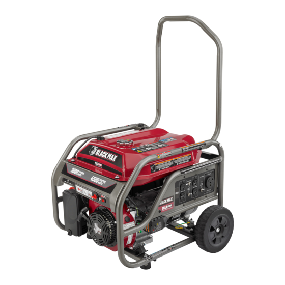
3600 WATT GENERATOR
GENERADOR 3 600 WATTS
BM903601/BM903631/
BM903631CVNM
To register your Black Max product,
please visit:
www.blackmaxtools.com
Para registrar su producto de
Black Max, por favor visita:
www.blackmaxtools.com
NOTICE
Do not use E15 or E85 fuel in
this product. It is a violation of
federal law and will damage the
unit and void your warranty. Only use unleaded gasoline
containing up to 10% ethanol.
No utilice combustibles E15 o E85 con este producto. Esto
constituye una violación a la ley federal, dañará la unidad y
anulará la garantía. Utilice únicamente gasolina sin plomo
que contiene hasta 10% de etanol.
TABLE OF CONTENTS
Important Safety Instructions ................................................3-4
Specific Safety Rules ............................................................4-5
Symbols ................................................................................5-8
Electrical ...............................................................................8-9
Features .................................................................................10
Assembly ..........................................................................11-12
Operation ..........................................................................12-15
Maintenance .....................................................................15-18
Troubleshooting ................................................................19-20
Parts Ordering/Service ............................................. Back Page
WARNING:
To reduce the risk of injury, the user must
read and understand the operator's manual before using this
product.
SAVE THIS MANUAL FOR
FUTURE REFERENCE
AVISO
NEUTRAL FLOATING
NEUTRAL DE FLOTACIÓN
ÍNDICE DE CONTENIDO
Instrucciones de seguridad importantes ..............................3-4
Reglas de seguridad específicas ..........................................4-5
Símbolos ...............................................................................5-8
Aspectos eléctricos ............................................................9-10
Características .......................................................................11
Armado .............................................................................12-13
Funcionamiento ................................................................13-16
Mantenimiento ..................................................................17-20
Corrección de problemas .................................................21-22
Pedidos de piezas/servicio ................................. Pág. posterior
ADVERTENCIA:
usuario debe leer y comprender el manual del operador antes
de usar este producto.
GUARDE ESTE MANUAL
PARA FUTURAS CONSULTAS
Para reducir el riesgo de lesiones, el
Advertisement
Table of Contents

Related Manuals for Black Max BM903631


Summary of Contents for Black Max BM903631
-
Page 1: Table Of Contents
OPERATOR’S MANUAL MANUAL DEL OPERADOR 3600 WATT GENERATOR GENERADOR 3 600 WATTS BM903601/BM903631/ BM903631CVNM To register your Black Max product, please visit: www.blackmaxtools.com Para registrar su producto de Black Max, por favor visita: www.blackmaxtools.com NOTICE AVISO Do not use E15 or E85 fuel in this product. - Page 2 See this fold-out section for all of the figures referenced in the operator’s manual. Consulte esta sección desplegable para ver todas las figuras a las que se hace referencia en el manual del operador. Fig. 1 A - Handle release pin (conjunto de pasador de G - Oil drain plug (tapón de drenaje del aceite) N - Fuel valve (válvula de combustible) afloje de mango)
- Page 3 Fig. 2 Fig. 3 A - Socket wrench (llave de casquillo) B - Adjustable wrench (llave ajustable) Fig. 4 Fig. 6 Fig. 5 A - Axle (eje) B - Wheel (rueda) C - Washer (arandela) A - Bolt (perno) D - U-bracket (soporte en “U”) B - Frame (armazón) E - Hitch pin (pasador del enganche) C - Rubber foot (pie de goma)
- Page 4 Fig. 7 Fig. 12 Fig. 10 A - Put choke lever in START position [desplace de la palanca del anegador hasta la posición A - Oil cap/dipstick (tapa de relleno de aceite / START (ARRANQUE)] varilla medidora de aceite) B - Move choke lever to RUN [desplace de la B - Oil fill hole (agujero de llenado de aceite) palanca del anegador hasta la posición RUN (FUNCIONAMIENTO)]...
- Page 5 Fig. 20 Fig. 15 Fig. 18 A - Oil drain plug (tapón de drenaje del aceite) B - Oil cap/dipstick (tapa de relleno de aceite / varilla medidora de aceite) A - Carburetor drain screw (tornillo de drenaje Fig. 16 del carburador) A - Fuel valve (válvula de combustible) B - Hose barb (conector de manguera dentada)
- Page 6 To register your Black Max product, please visit: www.blackmaxtools.com LOCATE GENERATOR AT LEAST 20 FT.* AWAY TO REDUCE THE RISK OF CARBON MONOXIDE GETTING INSIDE THE HOME * Minimum distance as recommended by U.S. Department of Health and Human Services Centers for Disease Control and Prevention (www.cdc.gov/co). Your specific home and/or wind conditions may require additional distance.
-
Page 7: Important Safety Instructions
IMPORTANT SAFETY INSTRUCTIONS Do not start or operate the engine in a confined space, building, near open windows, or in other unventilated space DANGER: where dangerous carbon monoxide fumes can collect. Carbon Monoxide. Using a generator indoors CAN KILL Carbon monoxide, a colorless, odorless, and extremely YOU IN MINUTES. -
Page 8: Specific Safety Rules
IMPORTANT SAFETY INSTRUCTIONS Use only recommended or equivalent replacement parts Maintain the unit per maintenance instructions in this and accessories and follow instructions in the Maintenance Operator’s Manual. section of this manual. Use of any other parts or failure ... -
Page 9: Symbols
SPECIFIC SAFETY RULES The carbon monoxide shutoff feature on this generator these instructions can cause the monitor to malfunction is not a substitute for safe generator practices. Always which can result in death or serious personal injury. operate the generator in open, outdoor areas, at least ... - Page 10 SYMBOLS Some of the following symbols may be used on this product. Please study them and learn their meaning. Proper interpretation of these symbols will allow you to operate the product better and safer. SYMBOL NAME DESIGNATION/EXPLANATION To reduce the risk of serious injury, avoid attempting to lift the Lifting Hazard generator alone.
- Page 11 SYMBOLS CARBON MONOXIDE (CO) SENSOR In the event of a carbon monoxide hazard, the LED on the CO sensor will flash red and the generator will shut off. Leave the area immediately and relocate to an open outdoor area. Ventilate the area thoroughly before occupying again.
-
Page 12: Electrical
SYMBOLS SPARK ARRESTOR Operation of this equipment may create sparks that can start fires around dry vegetation. A spark arrestor may be required. The operator should contact local fire agencies for laws or regulations relating to fire prevention requirements. FUEL CAP WARNING Never remove fuel cap when unit is running. - Page 13 ELECTRICAL POWER MANAGEMENT NOTICE: To prolong the life of the generator and attached devices, Operating voltage and frequency requirement of all it is important to take care when adding electrical loads to electronic equipment should be checked prior to plug- the generator.
-
Page 14: Features
FEATURES PRODUCT SPECIFICATIONS ENGINE GENERATOR Engine Type ............212cc OHV Rated Voltage .............120 V Replacement Spark Plug .... Torch F7TC or equivalent Rated Amps .............. 30.0 A Lubricant Fill Volume ......approximately 18 oz. Rated Output*............3,600 W Fuel Volume ..............4 gal. Starting Watts ............ -
Page 15: Assembly
ASSEMBLY UNPACKING LOOSE PARTS LIST See Figure 2 This product requires assembly. The following items are included with the generator: Carefully cut the box down the sides then remove the machine and any accessories from the box. Make sure Description Qty. -
Page 16: Operation
ASSEMBLY INSTALLING THE WHEELS Raise the end of the generator where the handle is located high enough to gain access to the frame bottom; securely See Figure 5. position props underneath to support. Wheels are provided to assist in moving the generator to ... - Page 17 OPERATION CHECKING/ADDING LUBRICANT NOTICE: See Figure 7. Before each use, inspect the entire product for damaged, missing, or loose parts such as screws, nuts, bolts, caps, NOTICE: etc. Tighten securely all fasteners and caps and do not Attempting to start the engine before it has been properly operate this product until all missing or damaged parts filled with lubricant will result in equipment failure.
- Page 18 OPERATION ETHANOL-BLENDED FUELS STARTING THE ENGINE See Figures 9 - 10. NOTICE: NOTICE: Do not use E15 or E85 fuel in this product. It is a viola- tion of federal law and will damage the unit and void On a level surface with the engine off, check the lubricant your warranty.
-
Page 19: Maintenance
OPERATION MOVING THE GENERATOR Fold the handle to the down position. Never lift or carry this product using the handle. See Figure 12. NOTE: This tool is heavy and requires several people to Turn off the generator. lift. To avoid back injury, keep your knees bent and lift ... - Page 20 MAINTENANCE Remove the filter element. Measure plug gap. The correct gap is 0.028−0.031 in. (0.7– 0.8 mm). To widen gap, if necessary, carefully bend If the filter element is dirty, clean with warm, soapy water. the ground (top) electrode. To lessen gap, gently tap Rinse and let dry.
- Page 21 MAINTENANCE NOTE: Fuel tank must be empty before replacing fuel filter. Remove the fuel line from the hose barb by squeezing the ends of the retaining clip and sliding the fuel line off. Run unit until tank is empty, if needed, or inspect filter prior to fill-up.
- Page 22 MAINTENANCE STORAGE When preparing the generator for storage, allow the unit to cool for 30 minutes then follow the guidelines below. STORAGE TIME PRIOR TO STORING Less than 2 months Drain gasoline from tank and dispose of in a suitable container according to state and local ordinances. 2 months to 1 year ...
-
Page 23: Troubleshooting
TROUBLESHOOTING PROBLEM POSSIBLE CAUSE SOLUTION Engine will not start. No fuel. Fill fuel tank. Stale gasoline or water in gasoline. Drain entire system and refill with fresh fuel. Lubricant level is low. Engine is equipped with Low Oil Shutoff. If engine lubricant level is low, it must be filled before unit will start. - Page 24 TROUBLESHOOTING PROBLEM POSSIBLE CAUSE SOLUTION Engine lacks power. Air filter element clogged. Check air filter element. Clean or replace as needed. Engine stored without treating or Drain fuel and carburetor. Refuel with draining gasoline, or refueled with bad fresh gasoline. gasoline.
- Page 25 NOTES...
- Page 26 Para registrar su producto de Black Max, por favor visita: www.blackmaxtools.com UBIQUE EL GENERADOR A UNA DISTANCIA DE POR LO MENOS 6 M (20 PIES)* PARA REDUCIR EL RIESGO DE QUE EL MONÓXIDO DE CARBONO INGRESE EN LA CASA Distancia mínima recomendada por el Departamento de Salud y Servicios Humanos y por los Centros para el Control y la Prevención de Enfermedades de los Estados Unidos (www.cdc.gov/co).
-
Page 27: Instrucciones De Seguridad Importantes
INSTRUCCIONES DE SEGURIDAD IMPORTANTES No conecte la unidad al sistema eléctrico de un edificio a menos que el generador y el interruptor de transferencia PELIGRO: se hayan instalado correctamente y que un electricista Monóxido de carbono. Usar un generador en el interior calificado haya verificado la salida de energía eléctrica. -
Page 28: Reglas De Seguridad Específicas
INSTRUCCIONES DE SEGURIDAD IMPORTANTES Afloje la tapa del tanque de combustible para aliviar la Los generadores fijos instalados de manera permanente presión y para evitar que se escape combustible por la son la mejor alternativa para abastecer de electricidad tapa. -
Page 29: Símbolos
REGLAS DE SEGURIDAD ESPECÍFICAS durante el funcionamiento se puede producir una falla en aire libre. Ventile bien el área antes de volver a ocuparla. el motor o un daño a la herramienta. Asegúrese de que el generador esté ubicado en un lugar al aire libre, a una distancia de, al menos, 6, m (20 pies) ... - Page 30 SÍMBOLOS Es posible que se empleen en este producto algunos de los siguientes símbolos. Le suplicamos estudiarlos y aprender su significado. Una correcta interpretación de estos símbolos le permitirá utilizar mejor y de manera más segura el producto. SÍMBOLO NOMBRE DENOMINACIÓN/EXPLICACIÓN Alerta de seguridad Indica un peligro posible de lesiones personales.
- Page 31 SÍMBOLOS ETIQUETAS DE SEGURIDAD La siguiente información puede encontrarse en el generador. Para su propia seguridad, le sugerimos estudiar y entender todas la etiquetas antes de poner marcha el generador. Si se desprende de la unidad cualquiera de las etiquetas o se vuelven ilegibles, comuníquese con algún el servicio al cliente o con un centro de servicio calificado para obtener un reemplazo.
- Page 32 SÍMBOLOS ADVERTENCIA DE COMBUSTIBLE No fume al abastecer el combustible. No llene de más. El nivel de lleno es 25 mm (1 pulg.) debajo del cuello del tanque de combustible. Pare la marcha del motor cinco minutos antes del reabastecimiento de combustible para evitar que el calor del silenciador encienda los vapores de combustible.
-
Page 33: Aspectos Eléctricos
ASPECTOS ELÉCTRICOS CALIBRE DEL CORDÓN DE EXTENSIÓN Consulte el cuadro mostrado abajo para asegurarse de que el calibre de los cordones de extensión que utilice puedan con la carga eléctrica requerida. Los cordones de calibre insuficiente pueden causar una caída de voltaje, lo cual puede quemar el dispositivo y recalentar el cordón mismo. - Page 34 ASPECTOS ELÉCTRICOS CAPACIDAD DEL GENERADOR ADMINISTRACIÓN DE LA POTENCIA A fin de prolongar la vida útil del generador y los dispositivos Cerciórese que el generador pueda suministrar suficientes vatios acoplados, es importante tener cuidado al agregar cargas eléctricas de potencia continua (en marcha) y de sobrecorriente (al arrancar) al generador.
-
Page 35: Características
CARACTERÍSTICAS ESPECIFICACIONES DEL PRODUCTO MOTOR GENERADOR Tipo de motor ..........212 cc, OHV Voltaje nominal ............120 V Bujía de repuesto ....... Torch F7TC o equivalente Amperaje nominal............30,0 A Volumen de llenado de lubricante ...aprox. 0,53 l (18 onz. ) Salida nominal* ............3 600 W Volumen de combustible ........15,14 l (4 gal) Salida máxima ............4 500 W Frecuencia nominal ............60 Hz... -
Page 36: Armado
ARMADO DESEMPAQUETADO LISTA DE PIEZAS SUELTAS Vea la figura 2. Este producto requiere armarse. Los siguientes artículos incluidos con generador: Orte cuidadosamente los lados de la caja y después retire la herramienta y cualesquier accesorios de la caja. Núm. ref. -
Page 37: Funcionamiento
ARMADO INSTALACIÓN DE LAS RUEDAS a la parte inferior del bastidor; coloque firmemente cuñas debajo para apoyarlo. Vea la figura 5. Deslice pase el eje a través del agujero situado en el Las ruedas se proporcionan para ayudar a trasladar el centro de la rueda. - Page 38 FUNCIONAMIENTO En algunas áreas, se deben registrar los generadores en las respectivas compañías de servicios públicos locales. ADVERTENCIA: Si el generador es utilizado en una obra en construcción, No utilice ningún aditamento o accesorio no recomendado es posible que se deban respetar reglamentaciones por el fabricante de este producto.
- Page 39 FUNCIONAMIENTO Si está bajo el nivel, abastezca de lubricante el motor hasta que el nivel del fluido alcance la parte superior de ADVERTENCIA: la varilla. La gasolina y los vapores de la misma son extremadamente Vuelva a colocar la tapa de relleno de aceite/varilla inflamables y explosivos.
- Page 40 FUNCIONAMIENTO ARRANQUE DEL MOTOR TRASLADO EL GENERADOR Vea las figuras 9 y 10. Vea la figura 12. Apague la generador AVISO: Levante el mango. Teniendo la unidad en una superficie nivelada y con el Desconecte todos los equipos que estén enchufados al motor apagado, revise el nivel de lubricante cada vez generador.
-
Page 41: Mantenimiento
MANTENIMIENTO Para limpiar la unidad: Cualquier establecimiento o técnico de reparaciones calificado puede realizar el mantenimiento normal, el Con un cepillo de cerdas suaves y/o una aspiradora afloje reemplazo o la reparación de los dispositivos y sistemas y elimine la tierra y la basura. de control de emisiones, con repuestos originales o Limpie las aberturas de ventilación con aire a baja presión equivalentes. - Page 42 MANTENIMIENTO PARACHISPAS Reinstale la tapa de relleno de aceite/varilla medidora de aceite. Vea la figura 17. NOTA: El lubricante usado debe desecharse en un sitio de AVISO: desecho aprobado. Si necesita más información, consulte a un concesionario de aceite de la localidad. Este producto cuenta con un parachispas que ha sido evaluado por el Servicio Forestal del Departamento MANTENIMIENTO DE LA BUJÍA...
- Page 43 MANTENIMIENTO Vuelva a colocar la perilla de la válvula del combustible Quite la tubería del combustible de ambos lados del filtro en el alojamiento del generador. Empuje hacia adelante apretando los extremos del sujetador de retención con pinzas. hasta que la perilla quede segura en la posición.
- Page 44 MANTENIMIENTO ALMACENAMIENTO Al preparar el generador para guardarlo, deje que la unidad se enfríe durante 30 minutos y luego siga los lineamientos señalados abajo. TIEMPO DE ANTES DE GUARDARLO ALMACENAMIENTO Menos de dos meses V acíe el tanque de combustible y colóquelo en un recipiente apropiado según lo establecido por las disposiciones estatales y locales.
-
Page 45: Corrección De Problemas
CORRECCIÓN DE PROBLEMAS PROBLEMA CAUSA POSIBLE SOLUCIÓN El motor no arranca. No hay combustible. Llene el tanque de combustible. Gasolina rancia o agua rancia en la Drene todo el sistema y reabastézcalo con gasolina. combustible nuevo. Está bajo el nivel de lubricante. Este motor viene con una característica que apagará... - Page 46 CORRECCIÓN DE PROBLEMAS PROBLEMA CAUSA POSIBLE SOLUCIÓN Cuesta trabajo arrancar el Hay agua en la gasolina. Drene todo el sistema y reabastézcalo con motor. combustible nuevo. Está débil la chispa de la bujía. Reemplazar la bujía o comuníquese con un centro de servicio calificado.
- Page 47 NOTAS...
- Page 48 3600 WATT GENERATOR GENERADOR 3 600 WATTS BM903601/BM903631/ BM903631CVNM OPERATOR’S MANUAL MANUAL DEL OPERADOR SERVICE For parts or service, contact your service dealer. Please call 1-800-726-5760 or visit us online at www.b lackmaxtools.com for assistance. Be sure to provide all relevant information when you call or visit. A replacement parts list is also available online.
Need help?
Do you have a question about the BM903631 and is the answer not in the manual?
Questions and answers