Table of Contents
Advertisement
Available languages
Available languages
Quick Links
OPERATOR'S MANUAL
Manual del operador
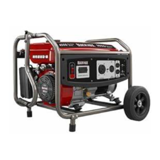
3650 WATT GENERATOR
Generador 3650 watts
BM903655D
BM903655D
Do not use E15 or E85 fuel (or fuel containing greater than 10% ethanol) in this product. It is a
violation of federal law and will damage the unit and void your warranty.
No utilice combustibles E15 o E85 (ni combustibles que contengan más de 10 % de etanol) con
este producto. Esto constituye una violación a la ley federal, dañará la unidad y anulará la garantía.
Your generator has been engineered and manufactured to our high standard for dependability, ease of operation, and
operator safety. When properly cared for, it will give you years of rugged, trouble-free performance.
:
WARNING
To reduce the risk of injury, the user must read and understand the operator's manual before using this
product. If you do not understand the warnings and instructions in the operator's manual, do not use this product.
SAVE THIS MANUAL FOR FUTURE REFERENCE
Su generador ha sido diseñado y fabricado de conformidad con estrictas normas para brindar fiabilidad, facilidad de uso
y seguridad para el operador. Con el debido cuidado, le brindará muchos años de sólido y eficiente funcionamiento.
ADVERTENCIA:
de usar este producto. Guarde este manual del operador y estúdielo frecuentemente para lograr un funcionamiento
seguro y continuo de este producto.
GUARDE ESTE MANUAL PARA FUTURAS CONSULTAS
NOTICE
Para reducir el riesgo de lesiones, el usuario debe leer y comprender el manual del operador antes
CUSTOMER SERVICE
SERVICIO AL CLIENTE
1-800-726-5760
NEUTRAL BONDED TO FRAME
PUNTO NEUTRO CONECTADO AL MARCO
AVISO
R
Advertisement
Chapters
Table of Contents

Related Manuals for Black Max BM903655D


Summary of Contents for Black Max BM903655D
- Page 1 OPERATOR’S MANUAL Manual del operador 3650 WATT GENERATOR Generador 3650 watts CUSTOMER SERVICE BM903655D SERVICIO AL CLIENTE BM903655D 1-800-726-5760 NEUTRAL BONDED TO FRAME PUNTO NEUTRO CONECTADO AL MARCO NOTICE AVISO Do not use E15 or E85 fuel (or fuel containing greater than 10% ethanol) in this product. It is a violation of federal law and will damage the unit and void your warranty.
- Page 2 See this fold-out section for all of the figures referenced in the operator’s manual. Consulte esta sección desplegable para ver todas las figuras a las que se hace referencia en el manual del operador.
- Page 3 Fig. 1 A - Recoil starter grip (mango del arrancador retráctil) K - Oil drainage bolt (perno de drenaje de aceite) B - Air filter (filtro de aire) L - Oil cap/dipstick (tapa de relleno de aceite/varilla medidora de aceite) C - Choke lever (palanca del anegador) M - Handle (mango) D - Fuel cap (tapa del tanque)
- Page 4 Fig. 7 Fig. 4 Fig. 10 A - Oil cap/dipstick (tapa de relleno de aceite/ A - Wheel (rueda) varilla medidora de aceite) B - Lock nut (tuerca de bloqueo) B - Lubricant fill hole (agujero de llenado de C - Bolt (perno) aceite) D - Wheel mounting hole (agujero para rueda) E - Spacer (espaciador)
- Page 5 Fig. 18 Fig. 13 Fig. 16 A - Select button (botón de selección) Fig. 14 A - Fuel line (conducto de combustible) B - Fuel valve (válvula de combustible) A - Spark plug (bujía) C - Petcock (llave de purga) B - Spark plug cap (tapa de la bujía) D - Off (apagado) Fig.
-
Page 6: Table Of Contents
TABLE OF CONTENTS Introduction ..................................2 Important Safety Instructions .............................3-4 Specific Safety Rules ..............................4 Symbols ..................................5-7 Electrical ..................................8-9 Features ..................................10 Assembly ................................11-12 Operation ................................13-15 Maintenance ................................16-18 Troubleshooting ................................19 ... -
Page 7: Important Safety Instructions
IMPORTANT SAFETY INSTRUCTIONS Do not start or operate the engine in a confined space, DANGER: building, near open windows, or in other unventilated space where dangerous carbon monoxide fumes can Carbon Monoxide. Using a generator indoors CAN KILL collect. Carbon monoxide, a colorless, odorless, and YOU IN MINUTES. -
Page 8: Specific Safety Rules
IMPORTANT SAFETY INSTRUCTIONS Use only authorized replacement parts and accessories Maintain the unit per maintenance instructions in this and follow instructions in the Maintenance section of this Operator’s Manual. manual. Use of unauthorized parts or failure to follow ... -
Page 9: Symbols
SYMBOLS The following signal words and meanings are intended to explain the levels of risk associated with this product. SYMBOL SIGNAL MEANING Indicates an imminently hazardous situation, which, if not avoided, will result DANGER: in death or serious injury. Indicates a potentially hazardous situation, which, if not avoided, could result WARNING: in death or serious injury. - Page 10 SYMBOLS Some of the following symbols may be used on this product. Please study them and learn their meaning. Proper interpretation of these symbols will allow you to operate the product better and safer. SYMBOL NAME DESIGNATION/EXPLANATION Volts Voltage Amperes Current Hertz Frequency (cycles per second)
- Page 11 SYMBOLS FUEL WARNING No smoking when filling with gasoline. Do not overfill. Full level is 1 in. below the top of the fuel neck. Stop the en- gine for five minutes before refueling to avoid the heat from the muffler igniting fuel vapors.
-
Page 12: Electrical
ELECTRICAL EXTENSION CORD CABLE SIZE Refer to the table below to ensure the cable size of the extension cords you use are capable of carrying the required load. Inadequate size cables can cause a voltage drop, which can damage the appliance and overheat the cord. Load in Watts Maximum Allowable Cord Length Current in... - Page 13 ELECTRICAL GENERATOR CAPACITY NOTICE: Make sure the generator can supply enough continuous (run- Do not overload the generator’s capacity. Exceeding the ning) and surge (starting) watts for the items you will power generator’s wattage/amperage capacity may damage at the same time. Follow these simple steps. the generator and/or electrical devices connected to it.
-
Page 14: Features
FEATURES PRODUCT SPECIFICATIONS ENGINE Rated Running Watts* ..........3,650 W Engine Type ............208 cc OHV Rated Starting Watts ..........4,550 W Replacement Spark Plug ........LG F7TC Rated Frequency ............60 Hz Engine Lubricant Volume........0.64 qts. DIMENSIONS Fuel Volume ..............4 gal. Length ................ 24 in. GENERATOR Width ................ -
Page 15: Assembly
ASSEMBLY UNPACKING LOOSE PARTS LIST See Figure 2. This product requires assembly. The following items are included with the generator: Carefully cut the box down the sides then remove the machine and any accessories from the box. Make sure that all items listed in the packing list are included. - Page 16 ASSEMBLY INSTALLING THE WHEELS ATTACHING THE HANDLE ASSEMBLY See Figure 4. See Figure 6. Wheels are provided to assist in moving the generator to the Locate the following items: desired location and should be installed on the same side Handle as the recoil starter.
-
Page 17: Operation
OPERATION Before each use, inspect the entire product for damaged, missing, or loose parts such as screws, nuts, bolts, caps, etc. DANGER: Tighten securely all fasteners and caps and do not operate Carbon Monoxide. Using a generator indoors CAN KILL this product until all missing or damaged parts are replaced. - Page 18 OPERATION USING FUEL STABILIZER CHECKING/ADDING FUEL See Figure 8. Fuel gets old, oxidizes, and breaks down over time. Adding a fuel stabilizer (not included) extends the usable life of fuel WARNING: and helps prevent deposits from forming that can clog the fuel system.
- Page 19 OPERATION STOPPING THE ENGINE Hour meter: The hour meter keeps track of how many hours the unit has been running during the current operation as See Figures 10 and 12. well as the total number of hours the unit has been used. To stop the engine under normal operating conditions: AC voltage: When selected, the AC voltage indicator will ...
-
Page 20: Maintenance
MAINTENANCE CHANGING ENGINE LUBRICANT WARNING: See Figure 15. When servicing, use only identical replacement parts. Remove the oil cap/dipstick. Use of any other parts could create a hazard or cause Place a container underneath the oil drain plug to collect product damage. - Page 21 MAINTENANCE CLEANING THE EXHAUST PORT AND DRAINING THE CARBURETOR MUFFLER Turn the engine switch OFF. Turn the fuel valve to the OFF position. Depending on the type of fuel used, the type and amount of lubricant used, and/or your operating conditions, the exhaust ...
- Page 22 MAINTENANCE STORAGE When preparing the generator for storage, allow the unit to cool completely then follow the guidelines below. STORAGE PRIOR TO STORING TIME Less than 2 Drain gasoline from tank and dispose of in a suitable container according to state and local ordinances. months 2 months to 1 ...
-
Page 23: Troubleshooting
TROUBLESHOOTING PROBLEM POSSIBLE CAUSE SOLUTION Engine will not start. Engine switch is OFF. Turn engine switch to ON. No fuel. Fill fuel tank. Stale gasoline or water in gasoline. Drain entire system and refill with fresh fuel. Lubricant level is low. Check engine lubricant level and fill, if necessary. -
Page 24: Warranty
WARRANTY BLACKMAX GENERATOR World Technologies, Inc., disclaims any and all express or implied warranties with respect to the gasoline engine. LIMITED WARRANTY ONE WORLD TECHNOLOGIES, INC., MAKES NO Proof of purchase must be presented when requesting WARRANTIES, REPRESENTATIONS OR PROMISES warranty service. - Page 25 WARRANTY LIMITED ENGINE WARRANTY DUCAR Corporation will repair or replace, free of charge, any are very often used in dusty or dirty conditions, which can cause part(s) of the engine that is defective in material or workmanship what appears to be premature wear. Such wear, when caused or both.
- Page 26 WARRANTY EMISSIONS CONTROL SYSTEM WARRANTY STATEMENT California, United States and Canada Emissions Control 3. No Charge Defects Warranty Statement Repair or replacement of any Warranted Part will be performed California, U.S. EPA and DUCAR are pleased to explain to explain no charge to the owner, including diagnostic labor which leads the Emissions Control System Warranty on your small off-road to the determination that a Warranted Part is defective, if the...
- Page 27 (1) Any warranted part that is not scheduled for replacement as required maintenance in the written instructions must be war- Your new BLACK MAX brand gasoline-powered product complies with ranted for the warranty period defined in subsection (b)(2). If any all applicable U.S.
- Page 28 ÍNDICE DE CONTENIDO Introducción ................................... 2 Instrucciones de seguridad importantes ........................3-4 Reglas de seguridad específicas ........................... 4 Símbolos ..................................5-7 Aspectos eléctricos ..............................8-9 Características ................................10 Armado ...................................11-12 Funcionamiento ..............................13-15 Mantenimiento ................................16-18 ...
-
Page 29: Instrucciones De Seguridad Importantes
INSTRUCCIONES DE SEGURIDAD IMPORTANTES de monóxido de carbono. El monóxido de carbono, un gas incoloro, inodoro y sumamente peligroso, puede causar la PELIGRO: pérdida de la conciencia o la muerte. Monóxido de carbono. Usar un generador en el interior LO Mantenga a todos los circunstantes, niños y animales por lo MATARÁ... -
Page 30: Reglas De Seguridad Específicas
INSTRUCCIONES DE SEGURIDAD IMPORTANTES Use únicamente repuestos y accesorios autorizados y siga las Mantenga la unidad según las instrucciones de mantenimiento instrucciones descritas en la sección de Mantenimiento de este señaladas en este manual del operador. manual. El empleo de piezas no autorizadas o el incumplimiento ... -
Page 31: Símbolos
SÍMBOLOS Las siguientes palabras de señalización y sus significados tienen el objeto de explicar los niveles de riesgo relacionados con este producto. SÍMBOLO SEÑAL SIGNIFICADO Indica una situación peligrosa inminente, la cual, si no se evita, causará PELIGRO: lesiones graves o mortales. Indica una situación peligrosa posible, la cual, si no se evita, podría causar ADVERTENCIA: lesiones graves o mortales. - Page 32 SÍMBOLOS Es posible que se empleen en este producto algunos de los siguientes símbolos. Le suplicamos estudiarlos y aprender su significado. Una correcta interpretación de estos símbolos le permitirá utilizar mejor y de manera más segura el producto. SÍMBOLO NOMBRE DENOMINACIÓN / EXPLICACIÓN Voltios Voltaje...
- Page 33 SÍMBOLOS ADVERTENCIA DE COMBUSTIBLE No fume al abastecer el combustible. No llene de más. El nivel de lleno es 25 mm (1 pulg.) debajo del cuello del tanque de combustible. Pare la marcha del motor cinco minutos antes del reabastecimiento de combustible para evitar que el calor del silenciador encienda los vapores de combustible.
-
Page 34: Aspectos Eléctricos
ASPECTOS ELÉCTRICOS CALIBRE DEL CORDÓN DE EXTENSIÓN Consulte el cuadro mostrado abajo para asegurarse de que el calibre de los cordones de extensión que utilice puedan con la carga eléctrica requerida. Los cordones de calibre insuficiente pueden causar una caída de voltaje, lo cual puede daño el dispositivo y recalentar el cordón mismo. - Page 35 ASPECTOS ELÉCTRICOS CAPACIDAD DEL GENERADOR AVISO: Cerciórese que el generador pueda suministrar suficientes vatios No exceda la capacidad del generador. Si excede la capacidad de potencia continua (en marcha) y de sobrecorriente (al arrancar) de corriente (amperios) y potencia (vatios) del generador puede para los equipos que desee alimentar al mismo tiempo.
-
Page 36: Características
CARACTERÍSTICAS ESPECIFICACIONES DEL PRODUCTO MOTOR Potencia nominal en marcha en vatios* ....3 650 W Tipo de motor ..........208 cc, OHV Potencia nominal en arranque en vatios ....4 550 W Bujía de repuesto ..........LG F7TC Frecuencia nominal ............60 Hz Volumen de aceite de motor ....0,61 L (0,64 cuartos) DIMENSIONES Volumen de combustible ......15,1 L (4 galones) Longitud .......... -
Page 37: Armado
ARMADO DESEMPAQUETADO LISTA DE PIEZAS SUELTAS Vea la figura 2. Este producto requiere armarse. Los siguientes accesorios vienen incluidos: Corte cuidadosamente los lados de la caja y después retire la herramienta y cualesquier accesorios de la caja. Núm. Asegúrese de que estén presentes todos los artículos ref. - Page 38 ARMADO INSTALACIÓN DE LAS RUEDAS COLOCACIÓN DEL MANGO Vea la figura 4. Vea la figura 6. Las ruedas se proporcionan para ayudar a trasladar el Localice los siguientes artículos: generador hasta la ubicación deseada y deben instalarse Mango del mismo lado que el arrancador retráctil. 2 Pernos (1/4-20 x 1,5 pulg.) Localice los siguientes artículos: 2 Tuerca de bloqueo (1/4-20)
-
Page 39: Funcionamiento
FUNCIONAMIENTO ADVERTENCIA: PELIGRO: Monóxido de carbono. Usar un generador en el interior No utilice ningún aditamento o accesorio no recomendado por el fabricante de este producto. El empleo de LO MATARÁ EN POCOS MINUTOS. aditamentos o accesorios no recomendados podría Los gases de escape del generador contienen niveles causar lesiones graves. - Page 40 FUNCIONAMIENTO VERIFICACIÓN Y ABASTECIMIENTO DE COMBUSTIBLES OXIGENADOS LUBRICANTE AVISO: Vea la figura 7. No utilice combustibles E15 o E85 (ni combustibles AVISO: que contengan más de 10 % de etanol) con este producto. Esto constituye una violación a la ley Si se intenta arrancar el motor antes de haberse abastecido federal, dañará...
- Page 41 FUNCIONAMIENTO ARRANQUE DEL MOTOR INFORMACIÓN SOBRE EL FUNCIONAMIENTO Vea las figuras 9 a 11. DE LA PANTALLA DIGITAL Vea la figura 13. AVISO: La pantalla digital muestra el voltaje de CA de salida, la Teniendo la unidad en una superficie nivelada y con el frecuencia, cuánto tiempo hace que el motor está...
-
Page 42: Mantenimiento
MANTENIMIENTO CAMBIO DEL LUBRICANTE DEL MOTOR ADVERTENCIA: Vea la figura 15. Al dar servicio a la unidad, sólo utilice piezas de repuesto Retire la tapa de relleno de aceite/varilla medidora de idénticas. El empleo de piezas diferentes podría causar aceite. - Page 43 MANTENIMIENTO Apriétela con una llave para comprimir la arandela. Si Ponga la válvula de combustible en la posición ON es nueva la bujía, gírela 1/2 vuelta para comprimir al (ENCENDIDO). nivel adecuado la arandela. Si va a volver a usar la bujía Una vez que se haya drenado todo el combustible del vieja, gírela de 1/8 a 1/4 de vuelta para comprimir al nivel tanque, cierre la válvula y vuelva a instalar el conducto...
- Page 44 MANTENIMIENTO ALMACENAMIENTO Al preparar el generador para guardarlo, deje que la unidad se enfríe por completo y luego siga los lineamientos señalados abajo. TIEMPO DE ANTES DE GUARDARLO ALMACENAMIENTO Menos de dos meses Vacíe el tanque de combustible y colóquelo en un recipiente apropiado según lo establecido por las disposiciones estatales y locales.
-
Page 45: Corrección De Problemas
CORRECCIÓN DE PROBLEMAS PROBLEMA CAUSA POSIBLE SOLUCIÓN El motor no arranca. El interruptor del motor está en apagado Ponga el interruptor del motor en (OFF). encendido (ON). No hay combustible. Llene el tanque de combustible. Gasolina rancia o agua rancia en la Drene todo el sistema y reabastézcalo con gasolina. -
Page 46: Garantía
GARANTÍA BLACKMAX GENERADOR la red de centros de servicio autorizados del fabricante del motor. One World Technologies, Inc., niega cualquier y todo GARANTÍA DE LIMITADA expresado o las garantías implícitas con respecto al motor Debe presentarse prueba de la compra al solicitar servicio al de gasolina. - Page 47 GARANTÍA GARANTÍA LIMITADA AL MOTOR DUCAR Corporation reparará o sustituirá, sin cargo, cualquiera sucios o polvorientos, lo cual puede provocar lo que pareciera de las partes del motor que tenga defectos en la fabricación, los ser un desgaste prematuro. Dicho desgaste, cuando sea materiales o ambos.
- Page 48 GARANTÍA DECLARACIÓN DE GARANTÍA DEL SISTEMA DE CONTROL DE EMISIONES Declaración de garantía por defectos en el sistema de control de y la fabricación que puedan causar la falla de una de las Partes cu- emisiones para Canadá, Estados Unidos y California biertas por un período de dos años a partir de la entrega del motor a un comprador minorista.
- Page 49 Su nuevo producto a gasolina de BLACK MAX cumple con todas las normas en la subsección (b)(2). Si cualquier de dichas partes fallan durante de emisiones aplicables de la Dirección de protección ambiental (EPA) de...
- Page 50 NOTES/NOTAS Página 24 — Español...
- Page 51 NOTES/NOTAS Página 25 — Español...
- Page 52 OPERATOR’S MANUAL MANUAL DEL OPERADOR CALIFORNIA PROPOSITION 65 SERVICE For parts or service, contact your nearest Black Max authorized WARNING: service dealer. Be sure to provide all relevant information when This product, its exhaust, and other substances that may become air- you call or visit.
Need help?
Do you have a question about the BM903655D and is the answer not in the manual?
Questions and answers
Is there a push button battery start available for BM903655DA?
No, the Black Max BM903655D uses a recoil starter grip, not a push button battery start.
This answer is automatically generated