Table of Contents
Advertisement
Available languages
Available languages
Quick Links
OPERATOR'S MANUAL
Manual del operador
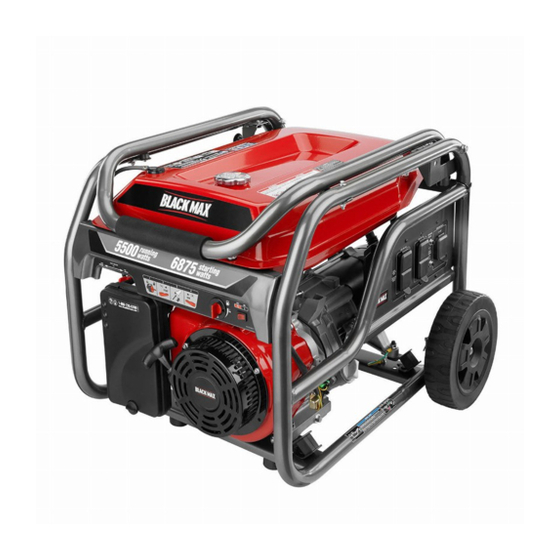
5,500 WATT GENERATOR
Generador de 5 500 W
BM905530
NEUTRAL BONDED TO FRAME
PUNTO NEUTRO CONECTADO AL MARCO
TABLE OF CONTENTS
Important Safety Instructions ...............................................3-4
Specific Safety Rules ...........................................................4-5
Symbols ...............................................................................5-8
Electrical ............................................................................8-10
Features ...........................................................................10-11
Assembly .........................................................................11-12
Operation .........................................................................13-15
Maintenance ....................................................................16-19
Troubleshooting .................................................................... 20
Parts Ordering/Service .............................................Back Page
WARNING:
To reduce the risk of injury, the user must
read and understand the operator's manual before using this
product.
SAVE THIS MANUAL FOR
FUTURE REFERENCE
R
Do not use E15 or E85 fuel in
this product. It is a violation of
federal law and will damage
the unit and void your warranty. Only use unleaded gasoline
containing up to 10% ethanol.
No utilice combustibles E15 o E85 con este producto. Esto
constituye una violación a la ley federal, dañará la unidad
y anulará la garantía. Use únicamente gasolina sin plomo
con un contenido de hasta 10 % de etanol.
Instrucciones de seguridad importantes .............................. 3-4
Reglas de seguridad específicas ......................................... 4-5
Símbolos .............................................................................. 5-8
Aspectos eléctricos ............................................................ 8-10
Características ................................................................. 10-11
Armado ............................................................................. 11-12
Funcionamiento ................................................................ 13-16
Mantenimiento .................................................................. 16-19
Corrección de problemas .......................................................20
Pedidos de piezas/servicio .................................Pág. posterior
usuario debe leer y comprender el manual del operador antes
de usar este producto.
CUSTOMER SERVICE
1-800-726-5760
To register your Black Max product,
please visit:
http://register.blackmaxtools.com/
Mexico SERVICIO AL CLIENTE
01 800 843 1111
Para registrar su producto de
BlackMax, por favor visita:
http://register.blackmaxtools.com/
NOTICE
ÍNDICE DE CONTENIDO
ADVERTENCIA:
Para reducir el riesgo de lesiones, el
GUARDE ESTE MANUAL
PARA FUTURAS CONSULTAS
AVISO
Advertisement
Table of Contents

Related Manuals for Black Max BM905530


Summary of Contents for Black Max BM905530
-
Page 1: Table Of Contents
CUSTOMER SERVICE 1-800-726-5760 To register your Black Max product, please visit: http://register.blackmaxtools.com/ OPERATOR’S MANUAL Mexico SERVICIO AL CLIENTE Manual del operador 01 800 843 1111 5,500 WATT GENERATOR Para registrar su producto de BlackMax, por favor visita: Generador de 5 500 W http://register.blackmaxtools.com/... - Page 2 See this fold-out section for all of the figures referenced in the operator’s manual. Consulte esta sección desplegable para ver todas las figuras a las que se hace referencia en el manual del operador. Fig. 1 Fig. 2 A - Reset button (botón de reajuste) B - Test button (botón de prueba) N - Fuel valve (válvula de combustible) O - Handle lock pin (pasador de seguro del...
- Page 3 Fig. 3 Fig. 4 Fig. 6 Fig. 8 A - Socket wrench (llave de casquillo) B - Adjustable wrench (llave ajustable) A - Hitch pin (pasador del enganche) Fig. 5 B - Washer (arandela) C - Wheel (rueda) D - Axle (eje) E - U-bracket (soporte en “U”) A - Lanyard (correa) Fig.
- Page 4 Fig. 9 Fig. 12 Fig. 15 Fig. 16 A - Oil cap/dipstick (tapa de relleno de aceite/ A - Move choke lever left to start (desplace varilla medidora de aceite) izquierda la palanca del anegador para B - Oil fill hole (agujero de llenado de aceite) arrancar) B - Move choke lever right to run (desplace Fig.
- Page 5 Fig. 18 Fig. 20 Fig. 22 A - Spark plug (bujía) B - Spark plug cap (tapa de la bujía) Fig. 19 A - Fuel valve (válvula de combustible) B - Hose barb (conector de manguera dentada) C - Fuel line (conducto de combustible) A - Carburetor drain screw (tornillo de drenaje del carburador) Fig.
- Page 6 To register your Black Max product, please visit: www.blackmaxtools.com LOCATE GENERATOR AT LEAST 20 FT.* AWAY TO REDUCE THE RISK OF CARBON MONOXIDE GETTING INSIDE THE HOME * Minimum distance as recommended by U.S. Department of Health and Human Services Centers for Disease Control and Prevention (www.cdc.gov/co). Your specific home and/or wind conditions may require additional distance.
-
Page 7: Important Safety Instructions
IMPORTANT SAFETY INSTRUCTIONS Do not start or operate the engine in a confined space, building, near open windows, or in other unventilated DANGER: space where dangerous carbon monoxide fumes can Carbon Monoxide. Using a generator indoors CAN KILL collect. Carbon monoxide, a colorless, odorless, and YOU IN MINUTES. -
Page 8: Specific Safety Rules
IMPORTANT SAFETY INSTRUCTIONS Use only recommended or equivalent replacement parts Maintain the unit per maintenance instructions in this and accessories and follow instructions in the Mainte- Operator’s Manual. nance section of this manual. Use of any other parts or Inspect the unit before each use for loose fasteners, fuel failure to follow maintenance instructions may create a leaks, etc. -
Page 9: Symbols
SPECIFIC SAFETY RULES The carbon monoxide sensor on this generator is not DO NOT tamper with, adjust, or modify the carbon mon- designed to detect smoke, fire, or any other gas. It will oxide (CO) sensor module on your generator. Failure to only activate due to the presence of carbon monoxide follow these instructions can cause the monitor to mal- function which can result in death or serious personal... - Page 10 SYMBOLS Some of the following symbols may be used on this product. Please study them and learn their meaning. Proper interpretation of these symbols will allow you to operate the product better and safer. SYMBOL NAME DESIGNATION/EXPLANATION Safety Alert Indicates a potential personal injury hazard. To reduce the risk of injury, user must read and understand Read Operator’s Manual operator’s manual before using this product.
- Page 11 SYMBOLS Exhaust contains poisonous carbon monoxide gas that can cause uncon- sciousness or DEATH. Operate in well-ventilated, outdoor areas away from open windows or doors. Do not expose to rain or use in damp locations. Using a generator indoors CAN KILL YOU IN MINUTES.
-
Page 12: Electrical
SYMBOLS HOT SURFACE WARNING Do not touch the muffler or aluminum cylinder of the engine. They are very HOT and will cause severe burns. Don’t put body parts or any flammable or combustible materials in the direct path of the exhaust. CLEARANCE WARNING While operating and storing, keep at least 3 feet of clearance on all... - Page 13 ELECTRICAL ELECTRIC MOTOR LOADS It is characteristic of common electric motors in normal operation to draw up to six times their running current while starting. This table may be used to estimate the watts required to start electric motors; however, if an electric motor fails to start or reach running speed, turn off the appliance or tool immediately to avoid equipment damage.
-
Page 14: Features
ELECTRICAL POWER MANAGEMENT Estimated Estimated To prolong the life of the generator and attached devices, Application/Equipment Running Starting it is important to take care when adding electrical loads to Watts* Watts* the generator. There should be nothing connected to the generator outlets before starting its engine. -
Page 15: Assembly
FEATURES KNOW YOUR GENERATOR FUEL VALVE See Figure 2. Fuel flow from the fuel tank to the engine is turned on and The safe use of this product requires an understanding of the off using the fuel valve. information on the product and in this operator’s manual as GROUND TERMINAL well as a knowledge of the project you are attempting. - Page 16 ASSEMBLY INSTALLING FEET Do not discard the packing material until you have carefully inspected and satisfactorily operated the See Figure 5. product. Locate the following items: If any parts are damaged or missing, please call 2 rubber feet 1-800-726-5760 for assistance.
-
Page 17: Operation
OPERATION DANGER: WARNING: Carbon Monoxide. Using a generator indoors CAN KILL Do not allow familiarity with this product to make you YOU IN MINUTES. careless. Remember that a careless fraction of a second is sufficient to inflict serious injury. Generator exhaust contains high levels of carbon mon- oxide (CO), a poisonous gas you cannot see or smell. - Page 18 OPERATION USING FUEL STABILIZER In some areas, generators are required to be registered with local utility companies. Fuel gets old, oxidizes, and breaks down over time. Adding If the generator is used at a construction site, there may a fuel stabilizer (not included) extends the usable life of fuel be additional regulations which must be observed.
- Page 19 OPERATION WARNING: WARNING: Always shut off engine before fueling. Never remove fuel While operating and storing, keep at least 3 feet of clear- cap or add fuel to a machine with a running or hot engine. ance on all sides of this product, including overhead. Make sure the unit is sitting on a flat, level surface and Allow a minimum of 30 minutes of “cool down”...
-
Page 20: Maintenance
MAINTENANCE CHECKING/CLEANING AIR FILTER Normal maintenance, replacement or repair of emission con- trol devices and systems may be performed by any qualified See Figure 16. repair establishment or individual with original or equivalent For proper performance and long life, keep air filter clean. parts. - Page 21 MAINTENANCE chipped, spark plug should be replaced. For replacement Remove the fuel line from the hose barb by squeezing spark plug, see Product Specifications earlier in this the ends of the retaining clip and sliding the fuel line off. manual or the accompanying engine manual, if applicable.
- Page 22 MAINTENANCE Raise the handle to the up position. If transporting in a vehicle, drain the fuel tank, close the fuel valve and securely restrain the generator. Tilt the machine away from you until it balances on the Provide a plastic sheet or absorbent pad below the gen- wheels, then roll the machine to the desired location.
- Page 23 MAINTENANCE MAINTENANCE SCHEDULE NOTE: If a separate engine manual is provided for this generator, please follow the maintenance schedule provided in the engine manual instead of the maintenance information listed below. After 1st month Every 3 months Every 6 months Every year or Before or 20 hours of...
-
Page 24: Troubleshooting
TROUBLESHOOTING PROBLEM POSSIBLE CAUSE SOLUTION Engine will not start. No fuel. Fill fuel tank. Stale gasoline or water in gasoline. Drain entire system and refill with fresh fuel. Lubricant level is low. Engine is equipped with Low Oil Shutoff. If engine lubricant level is low, it must be filled before unit will start. - Page 25 Para registrar su producto de Black Max, por favor visita: www.blackmaxtools.com UBIQUE EL GENERADOR A UNA DISTANCIA DE POR LO MENOS 6 M (20 PIES)* PARA REDUCIR EL RIESGO DE QUE EL MONÓXIDO DE CARBONO INGRESE EN LA CASA Distancia mínima recomendada por el Departamento de Salud y Servicios Humanos y por los Centros para el Control y la Prevención de Enfermedades de los Estados Unidos (www.cdc.gov/co).
-
Page 26: Instrucciones De Seguridad Importantes
INSTRUCCIONES DE SEGURIDAD IMPORTANTES se hayan instalado correctamente y que un electricista calificado haya verificado la salida de energía eléctrica. PELIGRO: La conexión debe aislar la corriente del generador del Monóxido de carbono. Usar un generador en el interior servicio público y debe cumplir con todas las leyes y los LO MATARÁ... -
Page 27: Reglas De Seguridad Específicas
INSTRUCCIONES DE SEGURIDAD IMPORTANTES Después de reabastecer de combustible la unidad ponga al hogar durante los cortes de energía. Incluso la tapa y apriétela firmemente. los generadores portátiles que están conectados correctamente pueden sobrecargarse. De esta manera, Limpie todo el combustible que se haya derramado de los componentes del generador pueden recalentarse o la unidad. -
Page 28: Símbolos
REGLAS DE SEGURIDAD ESPECÍFICAS Apague el motor y déjelo enfriar durante cinco minutos Asegúrese de que el generador esté ubicado en un lugar antes de agregar gasolina o lubricante al generador. al aire libre, a una distancia de, al menos, 6 m (20 pies) de todas las puertas, ventanas y espacios ocupadas. - Page 29 SÍMBOLOS Es posible que se empleen en este producto algunos de los siguientes símbolos. Le suplicamos estudiarlos y aprender su significado. Una correcta interpretación de estos símbolos le permitirá utilizar mejor y de manera más segura el producto. SÍMBOLO NOMBRE DESIGNACIÓN/EXPLICACIÓN Alerta de seguridad Indica un peligro posible de lesiones personales.
- Page 30 SÍMBOLOS El escape contiene gas venenoso de monóxido de carbono que puede causar pérdida del conocimiento a la MUERTE. Opere en áreas exteriores bien ventiladas lejos de puertas o ventanas abiertas. No exponga la unidad a la lluvia ni la use en lugares húmedos.
-
Page 31: Aspectos Eléctricos
SÍMBOLOS ADVERTENCIA DE SUPERFICIE CALIENTE No toque el silenciador ni el cilindro de aluminio del motor. Están muy CALIENTES y causan quemaduras graves. No ponga ningún partes del cuerpo o material inflamable o combustible directamente en la trayectoria de las emanaciones del escape. ADVERTENCIA DE ESPACIO LIBRE Tanto en funcionamiento como... - Page 32 ASPECTOS ELÉCTRICOS CARGAS DE MOTORES ELÉCTRICOS Es característico en el funcionamiento normal de los motores eléctricos comunes consumir durante el arranque hasta seis veces su corriente de operación. Esta tabla puede emplearse para estimar la potencia necesaria (en vatios) para arrancar los motores eléctricos;...
-
Page 33: Características
ASPECTOS ELÉCTRICOS ADMINISTRACIÓN DE LA POTENCIA W de W de A fin de prolongar la vida útil del generador y los dispositivos Arranque Herramienta o aparato Funcionamiento acoplados, es importante tener cuidado al agregar cargas Adicionales Estimados* eléctricas al generador. NO debe haber equipo alguno conectado Estimados* a los tomacorrientes del generador antes de poner en marcha el Emergencia / En casa... -
Page 34: Armado
CARACTERÍSTICAS FAMILIARÍCESE CON EL GENERADOR VÁLVULA DE COMBUSTIBLE Vea la figura 2. El flujo de combustible del tanque de combustible al motor El uso seguro que este producto requiere la comprensión se activa y desactiva con la válvula de combustible. de la información impresa en el producto y en el manual del TERMINAL DE CONEXIÓN A TIERRA operador así... - Page 35 ARMADO HERRAMIENTAS NECESARIAS Vea la figura 4. ADVERTENCIA: Para armar la unidad se necesitan las siguientes herramientas No utilice este producto si alguna pieza incluida en la (no incluido o dibujado para escalar): Lista de piezas sueltas ya está ensamblada al producto cuando lo desempaqueta.
-
Page 36: Funcionamiento
FUNCIONAMIENTO PELIGRO: ADVERTENCIA: Monóxido de carbono. Usar un generador en el interior No permita que su familiarización con este producto lo LO MATARÁ EN POCOS MINUTOS. vuelva descuidado. Tenga presente que un descuido de un instante es suficiente para causar una lesión grave. Los gases de escape del generador contienen niveles altos de monóxido de carbono (CO), un gas venenoso que no puede verse ni olerse. - Page 37 FUNCIONAMIENTO (Occupational Safety and Health Administration, OSHA) Desenrosque la tapa de relleno de aceite/varilla medidora generales o estatales, códigos u ordenanzas locales al uso de aceite y retírela. para el que fue diseñado el generador. Limpie la varilla de nivel y vuelva a asentarla en el agujero; Consulte a un electricista calificado, a un inspector de no la enrosque.
- Page 38 FUNCIONAMIENTO NOTA: Si el generador no está en una superficie nivelada, es posible que no arranque o se apague durante su ADVERTENCIA: funcionamiento. La gasolina y los vapores de la misma son extremadamente Desconecte todas las cargas del generador. inflamables y explosivos.
-
Page 39: Mantenimiento
FUNCIONAMIENTO OPERACIÓN A ALTITUDES ELEVADAS Para seguridad, inserta el pasador de seguro del mango para asegurar el mango antes de traslado. Su motor está configurado para funcionar por debajo de NOTA: Para ayudar a que el pasador de bloqueo del mango los 609,6 m (2 000 pies) de altitud medidos en la fábrica. - Page 40 MANTENIMIENTO Retire los elemento de filtro. Mida el espacio interelectródico. La separación correcta es 0,7-0,8 mm (0,028−0,031 pulg.). Para ampliar la separación, Si el elemento de filtro están sucios, lávese con agua doble con cuidado el electrodo (superior) de conexión a jabonosa tibia.
- Page 41 MANTENIMIENTO la abajo para poder acceder a la conector de manguera NOTA: El tanque de combustible debe estar vacío antes de dentada. reemplazar el filtro. Si es necesario, ponga en funcionamiento la unidad hasta vaciar el tanque, o supervise el filtro antes de Retire el conducto de combustible de la conector de llenarlo.
- Page 42 MANTENIMIENTO ALMACENAMIENTO Al preparar el generador para guardarlo, deje que la unidad se enfríe durante 30 minutos y luego siga los lineamientos señalados abajo. TIEMPO DE ANTES DE GUARDARLO ALMACENAMIENTO Menos de dos meses Vacíe el tanque de combustible y colóquelo en un recipiente apropiado según lo establecido por las disposiciones estatales y locales.
-
Page 43: Corrección De Problemas
CORRECCIÓN DE PROBLEMAS PROBLEMA CAUSA POSIBLE SOLUCIÓN El motor no arranca. No hay combustible. Llene el tanque de combustible. Gasolina rancia o agua rancia en la gasolina. Drene todo el sistema y reabastézcalo con combustible nuevo. Está bajo el nivel de lubricante. El motor posee un apagado por poco aceite. - Page 44 5,500 WATT GENERATOR Generador de 5 500 W BM905530 OPERATOR’S MANUAL MANUAL DEL OPERADOR SERVICE For parts or service, contact your service dealer. Please call 1-800-726-5760 or visit us online at www.b lackmaxtools.com for assistance. Be sure to provide all relevant information when you call or visit. A replacement parts list is also available online.
Need help?
Do you have a question about the BM905530 and is the answer not in the manual?
Questions and answers