Advertisement
Quick Links
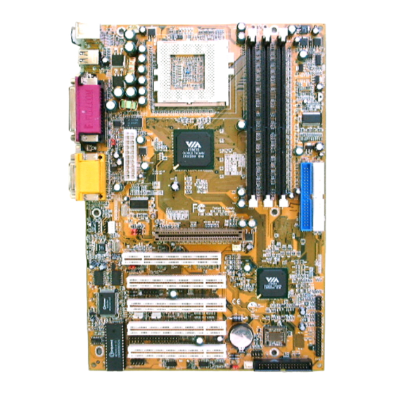
6V8633A
User's Manual Version 1.0
The information presented in this publication has been
carefully prepared to ensure reliability ; however, no
responsibility is assumed for inaccuracies.
Specifications are subject to change without notice.
IBM, PC/AT, and PC/XT are trademarks of Interna-
tional Business Machines Corporation.
Socket370 is a trademark of Intel Corporation
AWARD is a registered trademark of Phoenix
Software Inc.
MS-DOS and WINDOWS NT are registered
trademarks of Microsoft Corporation.
Trademarks and/or registered trademarks are the
properties of their respective owners.
i
Advertisement

Subscribe to Our Youtube Channel
Related Manuals for Acorp 6V8633A


Summary of Contents for Acorp 6V8633A
- Page 1 6V8633A User's Manual Version 1.0 The information presented in this publication has been carefully prepared to ensure reliability ; however, no responsibility is assumed for inaccuracies. Specifications are subject to change without notice. IBM, PC/AT, and PC/XT are trademarks of Interna- tional Business Machines Corporation.
- Page 2 Table of Contents Intrnctctinn Intrnctctinn Intrnctctinn Intrnctctinn Intrnctctinn 1. Mnthdranarc Ddrcriotinn 1. Mnthdranarc Ddrcriotinn 1. Mnthdranarc Ddrcriotinn 1. Mnthdranarc Ddrcriotinn 1. Mnthdranarc Ddrcriotinn 1.1 Fdattrdr 1.1.1 Harcward 1.1.1 Snetward 1.1.3 Attachmdntr 1.1 Mnthdranarc Inrtallatinn 1.1.1 Mnthdranarc Mao 1.1.1 Mnthdranarc Layntt 1.3 Mnthdranarc Cnnndctnrr 1.3.1 Frnnt Pandl Cnnndctnrr(PANEL( 1.3.1 Flnooy Dirk Cnnndctnr(FDD(...
- Page 3 Table of Contents 1.8 DDR SDRAM Inrtallatinn 1.8.1 DDR 1-10 1.8.1 Hnw tn inrtall a DDR Mnctld 1-10 1.9 Atcin Staryrtdm 1.9.1 CD-Atcin-IN Cnnndctnrr(CDIN1.CDIN1( 1-11 (notinn( (notinn( 1.10 Smart Pandl Nnanarc Cnnndctnr (notinn( (notinn( (notinn( 1.10.1 Pnrt 80 Ddatg Ftnctinn(ERR( 1-13 1.10.1 Sdcnnc BINS Cnnndctnr(BINS( 1-13...
- Page 4 Chaosdr 1 Chaosdr 1 Mnshdranarc Cdrbrhoshnn Mnshdranarc Cdrbrhoshnn Chaosdr 1 Chaosdr 1 Chaosdr 1 Mnshdranarc Cdrbrhoshnn Mnshdranarc Cdrbrhoshnn Mnshdranarc Cdrbrhoshnn Introduction System Overview This manual was written to help you start using this product as quickly and smoothly as possbile. Inside, you will find the answers to solve most problems.
- Page 5 Chaosdr 1 Chaosdr 1 Mnshdranarc Cdrbrhoshnn Mnshdranarc Cdrbrhoshnn Chaosdr 1 Chaosdr 1 Chaosdr 1 Mnshdranarc Cdrbrhoshnn Mnshdranarc Cdrbrhoshnn Mnshdranarc Cdrbrhoshnn 1.Motherboard Description 1.1 Features 1.1.1 Hardware -Socket 370 for Intel Celeron/PIII Processor. -Intel FC-PGA/PPGA Celeron Processors 300MHz~800MHz or higher processor with 66MHz FSB. -Intel FC-PGA Pentium III Processors 500MHz~1GHz processor with 100/133MHz FSB.
- Page 6 Chaosdr 1 Chaosdr 1 Mnshdranarc Cdrbrhoshnn Mnshdranarc Cdrbrhoshnn Chaosdr 1 Chaosdr 1 Chaosdr 1 Mnshdranarc Cdrbrhoshnn Mnshdranarc Cdrbrhoshnn Mnshdranarc Cdrbrhoshnn Green Function -Support power management operation via BIOS. -Wakes from power saving sleep mode at the press of any key or any mouse activity. Flash Memory -Support 2/4MB flash memory.
- Page 7 Chaosdr 1 Chaosdr 1 Mnshdranarc Cdrbrhoshnn Mnshdranarc Cdrbrhoshnn Chaosdr 1 Chaosdr 1 Chaosdr 1 Mnshdranarc Cdrbrhoshnn Mnshdranarc Cdrbrhoshnn Mnshdranarc Cdrbrhoshnn 1.1.2 Software BIOS -AWARD legal BIOS. -Supports APM 1.2. -Supports USB Function. -Supports ACPI Operation System -Offers the highest performance forMS-DOS,Windows, Windows NT, Windows 2000, Windows ME , Novell, OS/2, Windows 95/98, Windows 98 SE, UNIX, SCO UNIX etc.
- Page 8 Chaosdr 1 Chaosdr 1 Mnshdranarc Cdrbrhoshnn Mnshdranarc Cdrbrhoshnn Chaosdr 1 Chaosdr 1 Chaosdr 1 Mnshdranarc Cdrbrhoshnn Mnshdranarc Cdrbrhoshnn Mnshdranarc Cdrbrhoshnn 1.2 Motherboard Installation 1.2.1 Motherboard Map 1 - 5 1 - 5 1 - 5 1 - 5 1 - 5...
- Page 9 Chaosdr 1 Chaosdr 1 Mnshdranarc Cdrbrhoshnn Mnshdranarc Cdrbrhoshnn Chaosdr 1 Chaosdr 1 Chaosdr 1 Mnshdranarc Cdrbrhoshnn Mnshdranarc Cdrbrhoshnn Mnshdranarc Cdrbrhoshnn 1.2.2 Motherboard Layout FAN3 COM1 Printer COM2 Speak out Line in GAME1 MIC in AGP SLOT FAN2 ACR SLOT PCI1 PCI2 JCASE PCI3...
- Page 10 Chaosdr 1 Chaosdr 1 Mnshdranarc Cdrbrhoshnn Mnshdranarc Cdrbrhoshnn Chaosdr 1 Chaosdr 1 Chaosdr 1 Mnshdranarc Cdrbrhoshnn Mnshdranarc Cdrbrhoshnn Mnshdranarc Cdrbrhoshnn 1.3 Motherboard Connectors FAN3 COM1 Printer COM2 Speak out Line in GAME1 MIC in AGP SLOT FAN2 ACR SLOT PCI1 PCI2 JCASE PCI3...
- Page 11 Chaosdr 1 Chaosdr 1 Mnshdranarc Cdrbrhoshnn Mnshdranarc Cdrbrhoshnn Chaosdr 1 Chaosdr 1 Chaosdr 1 Mnshdranarc Cdrbrhoshnn Mnshdranarc Cdrbrhoshnn Mnshdranarc Cdrbrhoshnn 1.3.1 Front Panel Connector (PANEL) PANEL Connector PW_LED PW_BN KBLOCK RST_SW HD_LED EXTSMI SPEAK Speaker Connector (SPEAK) An offboard speaker can be installed onto the motherboard as a manufacturing option.
- Page 12 Chaosdr 1 Chaosdr 1 Mnshdranarc Cdrbrhoshnn Mnshdranarc Cdrbrhoshnn Chaosdr 1 Chaosdr 1 Chaosdr 1 Mnshdranarc Cdrbrhoshnn Mnshdranarc Cdrbrhoshnn Mnshdranarc Cdrbrhoshnn ATX Power Switch (PW_BN) The system power is controlled by a momentary switch connected to this lead. Pushing the button once will switch the system ON.
- Page 13 Chaosdr 1 Chaosdr 1 Mnshdranarc Cdrbrhoshnn Mnshdranarc Cdrbrhoshnn Chaosdr 1 Chaosdr 1 Chaosdr 1 Mnshdranarc Cdrbrhoshnn Mnshdranarc Cdrbrhoshnn Mnshdranarc Cdrbrhoshnn 1.3.4 ATX 20-pin Power Connector (ATX) This connector supports the power button on-board. Using the ATX power supply, functions such as Modem Ring Wake- Up and Soft Power Off are supported on this motherboard .
- Page 14 Chaosdr 1 Chaosdr 1 Mnshdranarc Cdrbrhoshnn Mnshdranarc Cdrbrhoshnn Chaosdr 1 Chaosdr 1 Chaosdr 1 Mnshdranarc Cdrbrhoshnn Mnshdranarc Cdrbrhoshnn Mnshdranarc Cdrbrhoshnn 1.4 Back Panel Connectors MIDI/(GAME) Port Parallel (Printer) Port (15-pin Fem ale) (25-pin Fem ale) PS/2 Mouse COM2 COM1 SPEAKER PS/2 Keyboard (6-pin Fem ale) Serial Port (9-pin Male)
- Page 15 Chaosdr 1 Chaosdr 1 Mnshdranarc Cdrbrhoshnn Mnshdranarc Cdrbrhoshnn Chaosdr 1 Chaosdr 1 Chaosdr 1 Mnshdranarc Cdrbrhoshnn Mnshdranarc Cdrbrhoshnn Mnshdranarc Cdrbrhoshnn Front USB2 Connectors: JUSB1/JUSB2 FAN3 COM1 Printer COM2 Speak out Line in GAME1 MIC in AGP SLOT FAN2 ACR SLOT PCI1 PCI2 JCASE...
- Page 16 Chaosdr 1 Chaosdr 1 Mnshdranarc Cdrbrhoshnn Mnshdranarc Cdrbrhoshnn Chaosdr 1 Chaosdr 1 Chaosdr 1 Mnshdranarc Cdrbrhoshnn Mnshdranarc Cdrbrhoshnn Mnshdranarc Cdrbrhoshnn 1.5 Serial and Parallel Interface Ports This system comes equipped with two serial ports and one parpllel port. Both types of interface ports will be explained in this chapter.
- Page 17 Chaosdr 1 Chaosdr 1 Mnshdranarc Cdrbrhoshnn Mnshdranarc Cdrbrhoshnn Chaosdr 1 Chaosdr 1 Chaosdr 1 Mnshdranarc Cdrbrhoshnn Mnshdranarc Cdrbrhoshnn Mnshdranarc Cdrbrhoshnn Signal DB9 Pin DB25 Pin Parallel Interface Port Unlike serial ports, parallel interface ports have been standardized and should not present any difficulty interfacing peripherals to your system.
- Page 18 Chaosdr 1 Chaosdr 1 Mnshdranarc Cdrbrhoshnn Mnshdranarc Cdrbrhoshnn Chaosdr 1 Chaosdr 1 Chaosdr 1 Mnshdranarc Cdrbrhoshnn Mnshdranarc Cdrbrhoshnn Mnshdranarc Cdrbrhoshnn 1.6 CPU Installation 1.6.1 CPU Installation Procedure: Socket 370 1. Pull the lever sideways away from the socket then raise the lever to a 90-degree angle.
- Page 19 Chaosdr 1 Chaosdr 1 Mnshdranarc Cdrbrhoshnn Mnshdranarc Cdrbrhoshnn Chaosdr 1 Chaosdr 1 Chaosdr 1 Mnshdranarc Cdrbrhoshnn Mnshdranarc Cdrbrhoshnn Mnshdranarc Cdrbrhoshnn 1.6.2 CPU Clock Frequency Setting: JCLK Overclocking is operating a CPU/Processor beyond its specified frequency. JCLK jumper is used for overclocking. FAN3 COM1 Printer...
- Page 20 Chaosdr 1 Chaosdr 1 Mnshdranarc Cdrbrhoshnn Mnshdranarc Cdrbrhoshnn Chaosdr 1 Chaosdr 1 Chaosdr 1 Mnshdranarc Cdrbrhoshnn Mnshdranarc Cdrbrhoshnn Mnshdranarc Cdrbrhoshnn 1.7 Jumper Setting A jumper has two or more pins that can be covered by a plastic jumper cap, allowing you to select different system options.
- Page 21 Chaosdr 1 Chaosdr 1 Mnshdranarc Cdrbrhoshnn Mnshdranarc Cdrbrhoshnn Chaosdr 1 Chaosdr 1 Chaosdr 1 Mnshdranarc Cdrbrhoshnn Mnshdranarc Cdrbrhoshnn Mnshdranarc Cdrbrhoshnn 1.7.2 Wake-On Modem Header: WOM Assignment 5V_SB Ground Signal 1.7.3 Wake-On LAN Header: WOL Assignment 5V_SB Ground Signal 1.7.4 CODEC Selection: J2 Assignment On board CODEC is used (Default)
- Page 22 Chaosdr 1 Chaosdr 1 Mnshdranarc Cdrbrhoshnn Mnshdranarc Cdrbrhoshnn Chaosdr 1 Chaosdr 1 Chaosdr 1 Mnshdranarc Cdrbrhoshnn Mnshdranarc Cdrbrhoshnn Mnshdranarc Cdrbrhoshnn NOTE: (Please follow the procedure below to clear CMOS data.) (1)Remove the AC power line. (2)CMOS(2-3)Closed. (3)Wait five seconds. (4)CMOS(1-2) Closed. (5)AC Power on.
- Page 23 Chaosdr 1 Chaosdr 1 Mnshdranarc Cdrbrhoshnn Mnshdranarc Cdrbrhoshnn Chaosdr 1 Chaosdr 1 Chaosdr 1 Mnshdranarc Cdrbrhoshnn Mnshdranarc Cdrbrhoshnn Mnshdranarc Cdrbrhoshnn 1.8 DDR SDRAM Installation 1.8.1 DDR DDR SDRAM Access Time: 2.5V Unbuffered PC1600/ PC2100 Type required. DDR SDRAM Type: 64MB, 128MB, 256MB, 512MB, 1GB DDR Module.
- Page 24 Chaosdr 1 Chaosdr 1 Mnshdranarc Cdrbrhoshnn Mnshdranarc Cdrbrhoshnn Chaosdr 1 Chaosdr 1 Chaosdr 1 Mnshdranarc Cdrbrhoshnn Mnshdranarc Cdrbrhoshnn Mnshdranarc Cdrbrhoshnn 1.9 Audio Subsystem FAN3 COM1 Printer COM2 Speak out Line in GAME1 MIC in AGP SLOT CDIN1 FAN2 CDIN2 ACR SLOT PCI1 PCI2 JCASE...
- Page 25 Chaosdr 1 Chaosdr 1 Mnshdranarc Cdrbrhoshnn Mnshdranarc Cdrbrhoshnn Chaosdr 1 Chaosdr 1 Chaosdr 1 Mnshdranarc Cdrbrhoshnn Mnshdranarc Cdrbrhoshnn Mnshdranarc Cdrbrhoshnn 1.10 Smart Panel Onboard Connector (option) FAN3 COM1 Printer COM2 Speak out Line in GAME1 MIC in AGP SLOT FAN2 ACR SLOT PCI1 PCI2...
- Page 26 Chaosdr 1 Chaosdr 1 Mnshdranarc Cdrbrhoshnn Mnshdranarc Cdrbrhoshnn Chaosdr 1 Chaosdr 1 Chaosdr 1 Mnshdranarc Cdrbrhoshnn Mnshdranarc Cdrbrhoshnn Mnshdranarc Cdrbrhoshnn 1.10.1 Port 80 Debug Function: ERR (option) Assignment Assignment Pin ERR Pin ERR ERD4 ERD0 ERD5 ERD1 ERD6 ERD2 ERD7 ERD3 1.10.2 Second BIOS Connector: JROM (option) Assignment...
- Page 27 Bhapter 1 Bhapter 1 BIOS Settp BIOS Settp Bhapter 1 Bhapter 1 Bhapter 1 BIOS Settp BIOS Settp BIOS Settp 2. BIOS Setup Introduction This manual discussed the Award Setup program built into the ROM BIOS. The Setup program allows the user to modify the basic system configuration.
- Page 28 Bhapter 1 Bhapter 1 BIOS Settp BIOS Settp Bhapter 1 Bhapter 1 Bhapter 1 BIOS Settp BIOS Settp BIOS Settp APM Support This AWARD BIOS supports Version 1.1&1.2 of the Advanced Power Management(APM) specification.Power management features are implemented via the System Management Interrupt(SMI).
- Page 29 Bhapter 1 Bhapter 1 BIOS Settp BIOS Settp Bhapter 1 Bhapter 1 Bhapter 1 BIOS Settp BIOS Settp BIOS Settp Keystroke Function Up arrow Move to previous item Down arrow Move to next item Left arrow Move to the item on the left(menu bar) Right arrow Move to the item on the right(menu bar) Main Menu: Quit without saving changes...
- Page 30 Bhapter 1 Bhapter 1 BIOS Settp BIOS Settp Bhapter 1 Bhapter 1 Bhapter 1 BIOS Settp BIOS Settp BIOS Settp 2.1 Main Menu Once you enter AWARD BIOS CMOS Setup Utility, the Main Menu will appear on the screen. The Main Menu allows you to select from several setup function.
- Page 31 Bhapter 1 Bhapter 1 BIOS Settp BIOS Settp Bhapter 1 Bhapter 1 Bhapter 1 BIOS Settp BIOS Settp BIOS Settp Advanced BIOS Features This setup page includes all the items of the BIOS special enchanced features. Advanced Chipset Features This setup page includes all the items of the Chipset special enchanced features.
- Page 32 Bhapter 1 Bhapter 1 BIOS Settp BIOS Settp Bhapter 1 Bhapter 1 Bhapter 1 BIOS Settp BIOS Settp BIOS Settp Load Optimized Defaults These settings are more likely to configure a workable computer when something is wrong. If you cannot boot the computer successfully, select the BIOS Setup options and try to diagnose the problem after the computer boots.
- Page 33 Bhapter 1 Bhapter 1 BIOS Settp BIOS Settp Bhapter 1 Bhapter 1 Bhapter 1 BIOS Settp BIOS Settp BIOS Settp 2.2 Standard CMOS Features This item in the Standard CMOS Setup Menu is divided into 10 categories. Each category includes no, one or more than one setup items.
- Page 34 Bhapter 1 Bhapter 1 BIOS Settp BIOS Settp Bhapter 1 Bhapter 1 Bhapter 1 BIOS Settp BIOS Settp BIOS Settp Main Menu Selections This table shows the selections that you can make on the Main Menu. Item Options Description Date Month DD YYYY Set the system,date.
- Page 35 Bhapter 1 Bhapter 1 BIOS Settp BIOS Settp Bhapter 1 Bhapter 1 Bhapter 1 BIOS Settp BIOS Settp BIOS Settp Item Options Description Halt On All Errors Select the situation in which you No Errors want the BIOS to stop the POST All, but Keyboard process and notify.
- Page 36 Bhapter 1 Bhapter 1 BIOS Settp BIOS Settp Bhapter 1 Bhapter 1 Bhapter 1 BIOS Settp BIOS Settp BIOS Settp 2.3 Advanced BIOS Features ◎ ◎ ◎ ◎ ◎ Figure 3. Advanced BIOS Features CMOS Setup Utility-Copyright(C) 1984-2001 Award Software Advanced BIOS Features Virus Warning Disabled...
- Page 37 Bhapter 1 Bhapter 1 BIOS Settp BIOS Settp Bhapter 1 Bhapter 1 Bhapter 1 BIOS Settp BIOS Settp BIOS Settp External Cache This fields allow you to Enable or Disable the CPU’S “Level 2” secondary cache. Caching allows better performance. Enabled (default) Enabled cache.
- Page 38 Bhapter 1 Bhapter 1 BIOS Settp BIOS Settp Bhapter 1 Bhapter 1 Bhapter 1 BIOS Settp BIOS Settp BIOS Settp Swap Floppy Drive If the system has two floppy drives, you can swap the logical drive name assignments. The Choices: Disabled(default), Enabled. Boot Up Floppy Seek Seek disk drives during boot up.
- Page 39 Bhapter 1 Bhapter 1 BIOS Settp BIOS Settp Bhapter 1 Bhapter 1 Bhapter 1 BIOS Settp BIOS Settp BIOS Settp Security Option This category allows you to limit access to the system and Setup, or just to Setup. System The system will not boot and access to Setup will be denied if the correct password is not entered in prompt.
- Page 40 Bhapter 1 Bhapter 1 BIOS Settp BIOS Settp Bhapter 1 Bhapter 1 Bhapter 1 BIOS Settp BIOS Settp BIOS Settp 2.4 Advanced Chipset Features This section allows you to configure the system based on the specific features of the installed chipset. This chipset manages bus speeds and access to system memory resources, such as DRAM and external cache.
- Page 41 Bhapter 1 Bhapter 1 BIOS Settp BIOS Settp Bhapter 1 Bhapter 1 Bhapter 1 BIOS Settp BIOS Settp BIOS Settp DRAM Clock This item determines DRAM Clock following the CPU host clock. The Choices: By SPD(default), Host CLK, HCLK-33, HCLK+33. DRAM Timing The Choices: By SPD(default), Manual.
- Page 42 Bhapter 1 Bhapter 1 BIOS Settp BIOS Settp Bhapter 1 Bhapter 1 Bhapter 1 BIOS Settp BIOS Settp BIOS Settp AGP Mode The Choices: 4X(default), 2X, 1X. AGP Driving Control By choosing “Auto” the system BIOS will enable the AGP output Buffer Drive strength that were defined by AGP Card.
- Page 43 Bhapter 1 Bhapter 1 BIOS Settp BIOS Settp Bhapter 1 Bhapter 1 Bhapter 1 BIOS Settp BIOS Settp BIOS Settp CPU to PCI Write Buffer When this field is Enabled, write from the CPU to the PCI bus are buffered, to compensate for the speed differences between the CPU and the PCI bus.
- Page 44 Bhapter 1 Bhapter 1 BIOS Settp BIOS Settp Bhapter 1 Bhapter 1 Bhapter 1 BIOS Settp BIOS Settp BIOS Settp 2.5 Integrated Peripherals ◎ ◎ ◎ ◎ ◎ Figure 5. Integrated Peripherals CMOS Setup Utility-Copyright(C) 1984-2001 Award Software Integrated Peripherals VIA Onchip IDE Device Press Enter Item Help...
- Page 45 Bhapter 1 Bhapter 1 BIOS Settp BIOS Settp Bhapter 1 Bhapter 1 Bhapter 1 BIOS Settp BIOS Settp BIOS Settp IDE Prefetch Mode The onboard IDE drive interface supports IDE prefetching, for faster drive access. If you install a primary and or secondary add-in IDE interface, set this field to Disabled if the interface does not support prefetching.
- Page 46 Bhapter 1 Bhapter 1 BIOS Settp BIOS Settp Bhapter 1 Bhapter 1 Bhapter 1 BIOS Settp BIOS Settp BIOS Settp Primary Slave UDMA Auto (default) BIOS will automatically detect the IDE HDD Accessing mode. Disabled Disabled. Secondary Master UDMA Auto (default) BIOS will automatically detect the IDE HDD Accessing mode.
- Page 47 Bhapter 1 Bhapter 1 BIOS Settp BIOS Settp Bhapter 1 Bhapter 1 Bhapter 1 BIOS Settp BIOS Settp BIOS Settp VIA-3043 Onchip LAN The Choices: Disabled(default), Enabled. CMOS Setup Utility-Copyright(C) 1984-2001 Award Software Super IO Device Onboard FDC Controller Enabled Item Help Onboard Serial Port 1 3F8/IRQ4...
- Page 48 Bhapter 1 Bhapter 1 BIOS Settp BIOS Settp Bhapter 1 Bhapter 1 Bhapter 1 BIOS Settp BIOS Settp BIOS Settp 3E8/IRQ4 Enabled onboard Serial Port2 and address is 3E8. 2E8/IRQ3 Enabled onboard Serial Port2 and address is 2E8. Disabled Disabled. UART Mode Select This item allows you to select which Infra Red(IR) function of the onboard I/O chip you wish to use.
- Page 49 Bhapter 1 Bhapter 1 BIOS Settp BIOS Settp Bhapter 1 Bhapter 1 Bhapter 1 BIOS Settp BIOS Settp BIOS Settp Midi Port Address Set Midi Port address to 300. 330 (default) Set Midi Port address to 330. Midi Port IRQ 10 (default) Set Midi Port IRQ to 10.
- Page 50 Bhapter 1 Bhapter 1 BIOS Settp BIOS Settp Bhapter 1 Bhapter 1 Bhapter 1 BIOS Settp BIOS Settp BIOS Settp 2.6 Power Management Setup The Power Management Setup allows you to configure your system to most effectively save energy while operating in a manner consistent with your own style of computer use.
- Page 51 Bhapter 1 Bhapter 1 BIOS Settp BIOS Settp Bhapter 1 Bhapter 1 Bhapter 1 BIOS Settp BIOS Settp BIOS Settp HDD Power Down By default, this is “Disabled”, meaning that no matter the mode of the rest of the system, the hard drive will remain ready.
- Page 52 Bhapter 1 Bhapter 1 BIOS Settp BIOS Settp Bhapter 1 Bhapter 1 Bhapter 1 BIOS Settp BIOS Settp BIOS Settp Modem Use IRQ This determines the IRQ, which can be applied in Modem use. 3(default) 4/5/7/9/10/11/NA Soft-Off by PWRBTN Pressing the power button for more than 4 seconds forces the system to enter the Soft-Off state when the system has “hung”.
- Page 53 Bhapter 1 Bhapter 1 BIOS Settp BIOS Settp Bhapter 1 Bhapter 1 Bhapter 1 BIOS Settp BIOS Settp BIOS Settp IRQ / Event Activity Monitoring If you highlight the “Press Enter” next to the “Wake Up Events” label and then press the enter key, it will take you to a submenu with the following options: When set to On, any event occurring at a VGA port will awaken a system which has been powered down.
- Page 54 Bhapter 1 Bhapter 1 BIOS Settp BIOS Settp Bhapter 1 Bhapter 1 Bhapter 1 BIOS Settp BIOS Settp BIOS Settp IRQs Activity Monitoring When set to On(default), any event occurring at Primary INTR will awaken a system which has been powered down.
- Page 55 Bhapter 1 Bhapter 1 BIOS Settp BIOS Settp Bhapter 1 Bhapter 1 Bhapter 1 BIOS Settp BIOS Settp BIOS Settp 2.7 PnP/PCI Configurations This section describes configuring the PCI bus system. PCI or Personal Computer Interconnect,is a system which allows I/O devices to operate at speeds nearing the speed of the CPU itself uses when communicating with its own special components.
- Page 56 Bhapter 1 Bhapter 1 BIOS Settp BIOS Settp Bhapter 1 Bhapter 1 Bhapter 1 BIOS Settp BIOS Settp BIOS Settp Reset Configuration Data The system BIOS supports the PnP feature so the system needs to record which resource is assigned and proceeds resources from conflict.
- Page 57 Bhapter 1 Bhapter 1 BIOS Settp BIOS Settp Bhapter 1 Bhapter 1 Bhapter 1 BIOS Settp BIOS Settp BIOS Settp The above settings will be shown on the screen only if “Manual” is chosen for the resources controlled by function. Legacy is the term which signifies that a resource is assigned to the ISA Bus and provides for non-PnP ISA add-on cards.
- Page 58 Bhapter 1 Bhapter 1 BIOS Settp BIOS Settp Bhapter 1 Bhapter 1 Bhapter 1 BIOS Settp BIOS Settp BIOS Settp PCI / VGA Palette Snoop Choose Disabled or Enabled. Some graphic controllers which are not VGA compatible take the output from a VGA controller and map it to their display as a way to provide boot information and VGA compatibility.
- Page 59 Bhapter 1 Bhapter 1 BIOS Settp BIOS Settp Bhapter 1 Bhapter 1 Bhapter 1 BIOS Settp BIOS Settp BIOS Settp 2.8 PC Health Status ◎ ◎ ◎ ◎ ◎ Figure 8. PC Health Status CMOS Setup Utility-Copyright(C) 1984-2001 Award Software PC Health Status CPU Warning Temperature Disabled...
- Page 60 Bhapter 1 Bhapter 1 BIOS Settp BIOS Settp Bhapter 1 Bhapter 1 Bhapter 1 BIOS Settp BIOS Settp BIOS Settp CPU Warning Temperature(℃ ℃ ℃ ℃ ℃ ) Disabled (default) Disabled. 60 ℃ ℃ ℃ ℃ ℃ / / / / / 140℉ ℉ ℉ ℉ ℉ Monitor CPU Temp.at 60℃/ 140℉.
- Page 61 Bhapter 1 Bhapter 1 BIOS Settp BIOS Settp Bhapter 1 Bhapter 1 Bhapter 1 BIOS Settp BIOS Settp BIOS Settp 2.9 Frequency / Voltage Control ◎ ◎ ◎ ◎ ◎ Figure 9. Frequency / Voltage Control CMOS Setup Utility-Copyright(C) 1984-2001 Award Software Frequency / Voltage Control Auto Detect DIMM / PCI CLK Enabled...
- Page 62 Bhapter 1 Bhapter 1 BIOS Settp BIOS Settp Bhapter 1 Bhapter 1 Bhapter 1 BIOS Settp BIOS Settp BIOS Settp 2.10 Load Fail-Safe Defaults When you press <Enter> on this item, you get a confirmation dialog box with a message similar to: ◎...
- Page 63 Bhapter 1 Bhapter 1 BIOS Settp BIOS Settp Bhapter 1 Bhapter 1 Bhapter 1 BIOS Settp BIOS Settp BIOS Settp 2.11 Load Optimized Defaults When you press <Enter> on this item, you get a confirmation dialog box with a message similar to: ◎...
- Page 64 Bhapter 1 Bhapter 1 BIOS Settp BIOS Settp Bhapter 1 Bhapter 1 Bhapter 1 BIOS Settp BIOS Settp BIOS Settp 2.12 Set Supervisor / User Password ◎ ◎ ◎ ◎ ◎ Figure 12. Set Supervisor / User Password CMOS Setup Utility-Copyright(C) 1984-2001 Award Software Standard CMOS Features Frequency/Voltage Control Advanced BIOS Features...
- Page 65 Bhapter 1 Bhapter 1 BIOS Settp BIOS Settp Bhapter 1 Bhapter 1 Bhapter 1 BIOS Settp BIOS Settp BIOS Settp Password Disabled If you select “System” at the Security Option of BIOS Features Setup Menu, you will be prompted for the password every time when the system is rebooted, or any time when you try to enter Setup.
- Page 66 Bhapter 1 Bhapter 1 BIOS Settp BIOS Settp Bhapter 1 Bhapter 1 Bhapter 1 BIOS Settp BIOS Settp BIOS Settp 2.13 Save & Exit Setup ◎ ◎ ◎ ◎ ◎ Figure 13. Save & Exit Setup CMOS Setup Utility-Copyright(C) 1984-2001 Award Software Standard CMOS Features Frequency/Voltage Control Advanced BIOS Features...
- Page 67 Bhapter 1 Bhapter 1 BIOS Settp BIOS Settp Bhapter 1 Bhapter 1 Bhapter 1 BIOS Settp BIOS Settp BIOS Settp 2.14 Exit Without Saving ◎ ◎ ◎ ◎ ◎ Figure 14. Exit Without Saving CMOS Setup Utility-Copyright(C) 1984-2001 Award Software Standard CMOS Features Frequency/Voltage Control Advanced BIOS Features...
- Page 68 Date : Warranty Card/Technical Fault Report M/B Model No.: Vender Serial No. Date of Purchase: Hardware Configuration Used : RAM (Brand,MB ) Video Card Hard Drive Other Card Diagnostic Software Used : Fault Description :...
- Page 69 Introduction There are motherboard drivers and utilities included in ACORP Bonus CD disc. You don't need to install all of them in order to boot your system. But after you finish the hardware installation, you have to install your operation system first (such as windows 98) before you can install any drivers or utilities.
- Page 70 Chaoser 3 Chaoser 3 Crhver Inrsallashnn Crhver Inrsallashnn Chaoser 3 Chaoser 3 Chaoser 3 Crhver Inrsallashnn Crhver Inrsallashnn Crhver Inrsallashnn 3.2 Installing VIA 4 in 1 Driver You can install the VIA 4 in 1 driver (IDE Bus master (For Windows NT use), VIA ATAPI Vendor Support Driver, VIA AGP, IRQ Routing Driver (For Windows 98 use), VIA Registry (INF) Driver) from the Bonus Pack CD disc auto-run menu.
- Page 71 Chaoser 3 Chaoser 3 Chaoser 3 Crhver Inrsallashnn Crhver Inrsallashnn Crhver Inrsallashnn Chaoser 3 Chaoser 3 Crhver Inrsallashnn Crhver Inrsallashnn 3.3 Installing Audio Driver This motherboard comes with an AC97 CODEC and the sound controller is in VIA South Bridge chipset. You can find the audio driver from the Bonus Pack CD disc auto- run menu.
- Page 72 Chaoser 3 Chaoser 3 Crhver Inrsallashnn Crhver Inrsallashnn Chaoser 3 Chaoser 3 Chaoser 3 Crhver Inrsallashnn Crhver Inrsallashnn Crhver Inrsallashnn (For Win98, Win ME & Win 2000 System) Click "Setup" Item. (For Win NT System) Click "Win NT" Item. (For Win NT System) Click "Setup"...
- Page 73 Chaoser 3 Chaoser 3 Chaoser 3 Crhver Inrsallashnn Crhver Inrsallashnn Crhver Inrsallashnn Chaoser 3 Chaoser 3 Crhver Inrsallashnn Crhver Inrsallashnn 3.4 Installing Hardware Monitoring Utility You can install Hardware Monitoring Utility to monitor CPU temperature, fans and system voltage. The hardware monitoring function is automatically implemented by the BIOS and utility software.
Need help?
Do you have a question about the 6V8633A and is the answer not in the manual?
Questions and answers