Table of Contents
Advertisement
Quick Links
Introduction
System Overview
This manual was written to help you start using this product
as quickly and smoothly as possbile. Inside you will find
the necessary explanations to solve most problems. In
order for this reference material to be of greatest use, refer
to the "expanded table of contents" to find relevant topics.
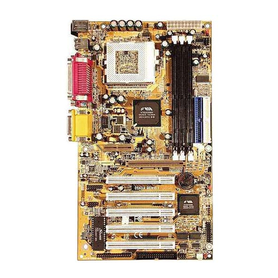
This board incorporates the system , I/O , and PCI IDE
into one board that provides a total PC solution. The
mainboard, Intel Celeron/Coppermine PII/PIII processor base
PC ATX system, support single processors with ISA Bus,
PCI Local Bus, and AGP Bus to support upgrades to your
system performance. It is ideal for multi-tasking and fully
supports MS-DOS, Windows, Windows NT , Windows ME,
Windows 2000 , Novell, OS/2, Windows95/98 , UNIX ,
SCO UNIX etc.
This manual also explains how to install the mainboard for
operation, and how to setup your CMOS configuration with
the BIOS setup program.
Chapter 1 Motherboard Description /1
Chapter 1 Motherboard Description /1
Chapter 1 Motherboard Description /1
Chapter 1 Motherboard Description /1
Chapter 1 Motherboard Description /1
Advertisement
Table of Contents

Subscribe to Our Youtube Channel
Related Manuals for Acorp 694XA


Summary of Contents for Acorp 694XA
- Page 1 Introduction System Overview This manual was written to help you start using this product as quickly and smoothly as possbile. Inside you will find the necessary explanations to solve most problems. In order for this reference material to be of greatest use, refer to the “expanded table of contents”...
- Page 2 1.Motherboard Description 1.1 Features 1.1.1 Hardware -Socket 370 for Intel Celeron/PIII Processor. -Intel FC-PGA/PPGA Celeron Processors 300MHz~800MHz or higher processor with 66/100MHz FSB. -Intel FC-PGA Pentium III Processors 500MHz~1GHz or higher processor with 100/133MHz FSB. -VIA Cyrix III Processor with 100/133MHz FSB. Chipset -North Bridge System Chipset : VIA VT82C694X support a 66/100/133 FSB.
-
Page 3: On-Board Ide
On-Board IDE -An IDE controller on the VT82C686B chipset provides IDE HDD/CD-ROM with PIO, Bus Master and Ultra DMA 33/66/100 operation modes. -Can connect up to four IDE devices. On-Board Peripherals -1 floppy port supports 2 FDC with 360K, 720K, 1.2M, 1.44M and 2.88M byte. - Page 4 1.1.2 Software BIOS -AWARD legal BIOS. -Supports APM 1.2. -Supports USB Function. -Supports ACPI. Operation System -Offers the highest performance for MS-DOS, Windows, Windows NT, Windows ME, Windows 2000, Novell, OS/2, Windows95/98, UNIX, SCO UNIX etc. 1.1.3 Attachments -HDD UDMA 66/100 Cable. -FDC Cable.
-
Page 5: Motherboard Installation
1.2 Motherboard Installation 1.2.1 Layout of Motherboard FAN1 USB1 COM1 Printer COM2 SPEAK OUT Line in GAME1 MIC in AMR SLOT AGP SLOT PCI1 ERR1 PCI2 PCI3 PCI4 PCI5 FAN2 BIOS1 Chapter 1 Motherboard Description /5 Chapter 1 Motherboard Description /5 Chapter 1 Motherboard Description /5 Chapter 1 Motherboard Description /5 Chapter 1 Motherboard Description /5... -
Page 6: Motherboard Connectors
1.3 Motherboard Connectors FAN1 USB1 COM1 Printer COM2 SPEAK OUT Line in GAME1 MIC in AMR SLOT AGP SLOT PCI1 ERR1 PCI2 PCI3 PCI4 PCI5 FAN2 BIOS1 1.Back Pannel I/O Connectors 1.Back Pannel I/O Connectors 1.Back Pannel I/O Connectors 1.Back Pannel I/O Connectors 1.Back Pannel I/O Connectors 2.CD Audio-In Connector 2.CD Audio-In Connector 2.CD Audio-In Connector... - Page 7 1.3.1 Front Panel Connector(PANEL1) PANEL1 Connector PW_LED PW_BN HD_LED RESET S5LED SMI_LED EXTSMI SPEAKER Speaker Connector (SPEAKR) An offboard speaker can be installed onto the motherboard as a manufacturing option. An offboard speaker can be connected to the motherboard at the front pannel connector. The speaker (onboard or offboard) provides error beep code information dur- ing the Power Self-Test when the computer cannot use the video interface.
- Page 8 ATX Power Switch (PW_BN) The system power is controlled by a momentary switch connected to this lead. Pushing the button once will switch the system ON. The system power LED lights when the system's power is on . Power LED Lead (PW_LED) The system Power LED lights when the system power is on.
- Page 9 1.3.4 ATX 20-pin Power Connector(PW1) This connector supports the power button on-board. Using the ATX power supply, functions such as Modem Ring Wake- Up and Soft Power Off are supported on this motherboard . This power connector supports instant power-on functionality, which means that the system will boot up instantly when the power connector is inserted on the board.
- Page 10 1.4 Back Pannel Connectors MIDI/(GAME) Port MIDI/(GAME) Port Parallel (Printer) Port Parallel (Printer) Port MIDI/(GAME) Port MIDI/(GAME) Port Parallel (Printer) Port Parallel (Printer) Port (15-pin Female) (15-pin Female) (15-pin Female) (15-pin Female) (25-pin Female) (25-pin Female) (25-pin Female) (25-pin Female) PS/2 Mouse PS/2 Mouse PS/2 Mouse...
- Page 11 Front Two USB Connectors: USB2 FAN1 USB1 COM1 Printer COM2 SPEAK OUT Line in GAME1 MIC in AMR SLOT AGP SLOT PCI1 ERR1 PCI2 PCI3 PCI4 PCI5 FAN2 BIOS1 USB 2 Chapter 1 Motherboard Description /11 Chapter 1 Motherboard Description /11 Chapter 1 Motherboard Description /11 Chapter 1 Motherboard Description /11 Chapter 1 Motherboard Description /11...
-
Page 12: Serial And Parallel Interface Ports
1.5 Serial and Parallel Interface Ports This system comes equipped with two serial ports and one parallel port. Both types of interface ports will be explained in this chapter. The Serial Interfaces: COM1/COM2 The serial interface port is sometimes refered to as an RS- 232 port or an asynchronous communication port. -
Page 13: Parallel Interface Port
Signal DB9 Pin DB25 Pin Parallel Interface Port Unlike serial ports, parallel interface ports have been standardized and should not present any difficulty interfacing peripherals to your system. Sometimes called a Centronics port, the parallel port is almost exclusively used with printers. The parallel port on your system has a 25-pin, DB 25 connector(see picture below). -
Page 14: Cpu Installation
1.6 CPU Installation 1.6.1 CPU Installation Procedure: Socket 370 1. Pull the lever sideways away from the socket then raise the lever to a 90-degree angle. 2. Locate Pin 1 in the socket and look for the white dot or cut edge in the CPU. - Page 15 1.6.2 CPU Frequency Selection: CLK1 Overclocking is operating a CPU/Processor beyond its specified frequency.CLK1 jumper is used for overclocking. FAN1 USB1 COM1 Printer COM2 SPEAK OUT Line in GAME1 MIC in AMR SLOT AGP SLOT PCI1 ERR1 PCI2 PCI3 PCI4 PCI5 C P U C P U...
-
Page 16: Jumper Setting
1.7 Jumper Setting A jumper has two or more pins that can be covered by a plastic jumper cap, allowing you to select different system options. FAN1 FAN1 Connector USB1 COM1 Printer COM2 SPEAK OUT Line in GAME1 MIC in AMR SLOT AGP SLOT PCI1... - Page 17 1.7.2 Wake-On Modem Header: WOM1 P i n P i n P i n A s s i g n m e n t A s s i g n m e n t A s s i g n m e n t P i n P i n A s s i g n m e n t...
-
Page 18: Dram Installation
1.8 DRAM Installation 1.8.1 DIMM DRAM Access Time: 3.3V Unbuffered SDRAM/ PC66/ PC100 and PC133 Type required. DRAM Type: 8MB, 16MB, 32MB, 64MB, 128MB, 256MB , 512MB DIMM Module.(168 pin) Bank Memory module DIMM 1 16MB, 32MB, 64MB, 128MB, 256, 512MB ( Bank 0-1 ) 168 pin, 3.3v SDRAM DIMM 2... -
Page 19: Audio Subsystem
1.9 Audio Subsystem FAN1 USB1 COM1 Printer COM2 SPEAK OUT Line in GAME1 MIC in AMR SLOT AGP SLOT CDIN1 CDIN2 PCI1 ERR1 PCI2 PCI3 PCI4 PCI5 FAN2 BIOS1 1.9.1 CD Audio-In Connectors:CDIN1/CDIN2 Assignment Pin CDIN1 CD-L CD-R Assignment Pin CDIN2 CD-L CD-R Chapter 1 Motherboard Description /19... - Page 20 1.10 Smart Panel Onboard Connector (option) FAN1 USB1 COM1 Printer COM2 SPEAK OUT Line in GAME1 MIC in AMR SLOT AGP SLOT PCI1 ERR1 ERR1 /JP1 PCI2 PCI3 PCI4 PCI5 FAN2 BIOS1 BIOS1 Note: The motherboard provides for Smart Panel. If you refer POST Error Code or Smart Panel function, please refer to Smart Panel (SP694XA) manual.
- Page 21 1.10.1 System State Show Connector:J2 (option) Signal Signal Vcc5SB S3LED+ GPO4 Vcc5SB GPO5 S1LED+ GPO8 Vcc5SB 1.10.2 Second BIOS Connector:BIOS1 (option) Assignment Assignment Pin BIOS1 Pin BIOS1 DISABLE ROMCS- MEMR- MEMW- SA18 SA10 SA17 SA11 SA16 SA12 SA15 SA13 SA14 Chapter 1 Motherboard Description /21 Chapter 1 Motherboard Description /21 Chapter 1 Motherboard Description /21...
- Page 22 1.10.3 Port 80 Debug Function Connector:ERR1/JP1 (option) Assignment Assignment Pin ERR1 Pin ERR1 ERD0 ERD1 ERD2 ERD3 ERD4 ERD5 ERD6 ERD7 Assignment Pin JP1 ERD4 ERD5 ERD6 ERD7 22 / Chapter 1 Motherboard Description 22 / Chapter 1 Motherboard Description 22 / Chapter 1 Motherboard Description 22 / Chapter 1 Motherboard Description 22 / Chapter 1 Motherboard Description...
Need help?
Do you have a question about the 694XA and is the answer not in the manual?
Questions and answers