Table of Contents
Advertisement
6A815E1/EP1
User's Manual Version 1.0
The information presented in this publication has been
made carefully for reliability; however, no responsibility
is assumed for inaccuracies. Specifications are subject
to change without notice.
IBM, PC/AT, and PC/XT are trademarks of Interna-
tional Business Machines Corporation.
Socket370 is a trademark of Intel Corporation
AWARD is a registered trademark of Phoenix
Software Inc.
MS-DOS and WINDOWS NT are registered trade-
marks of Microsoft Corporation.
Trademarks and/or registered trademarks are the
properties of their respective owners.
Advertisement
Table of Contents

Related Manuals for Acorp 6A815E1


Summary of Contents for Acorp 6A815E1
- Page 1 6A815E1/EP1 User's Manual Version 1.0 The information presented in this publication has been made carefully for reliability; however, no responsibility is assumed for inaccuracies. Specifications are subject to change without notice. IBM, PC/AT, and PC/XT are trademarks of Interna- tional Business Machines Corporation.
-
Page 2: Table Of Contents
Table of Contents 1. Motherboard Description 1.1 Introduction 1.2 Package Contents 1.3 Features 1.4 6A815E1 & 6A815EP1 Motherboard Layout 1.5 CPU Installation 1.6 SDRAM Installation 1.7 Connectors & Jumper Setting 1.7.1 Back Panel Connectors 1.7.1.1 PS/2 Mouse/Keyboard CONN. 1.7.1.2 USB Connector: USB1 1-10 1.7.1.3 Serial Interface ports... - Page 3 Table of Contents 2. BIOS Setup 2.1 Main Menu 2.2 Standard CMOS Features 2.3 Advanced BIOS Features 2-10 2.4 Advanced Chipset Features 2-14 2.5 Integrated Peripherals 2-17 2.6 Power Management Setup 2-23 2.7 PnP/PCI Configurations 2-27 2.8 PC Health Status 2-31 2.9 Frequency/Voltage Control 2-33...
-
Page 4: Introduction
1.1 Introduction 1.1 Introduction 1.1 Introduction The 6A815E1&EP1 motherboard is designed for using Intel PIII Front Side Bus Frequency 133MHz CPU, which utilize the Socket-370 design and the memory size expandable to 512MB. This motherboard use the lastest Intel 815 B-step chipset,... -
Page 5: Features
-North Bridge System Chipset : Intel 815 B-step support 66/100/133 FSB. -South Bridge System Chipset : Intel ICH2. Biggest memory capacity 6A815E1/6A815EP1 is equipped with three DIMM socket to support (8MB to 512MB) 168 pin 3.3v SDRAM SPD(Special Presence Detect). Maximum memory up to 512MB. - Page 6 -1 floppy port supports 2 FDD with 360K,720K,1.2M, 1.44M and 2.88M byte. -2 serial ports (COM1+COM2(10 pin) ). -4 USB ports. -1 VGA port.(Only support by 6A815E1 M/B) -1 parallel port supports SPP/EPP/ECP mode. Audio -ICH2 chip integrated. -AC’97 CODEC on board .
- Page 7 ICH2 and GMCH with a bandwidth of 266MB/sec- twice the maximum bandwidth of the PCI bus. Integrated Graphics : (Only support 6A815E1 motherboard) Controller supports 3D hyper pipelined architecture, parallel data processing and compression, precise pixel interpolation, full 2D hardware acceleration, and motion video acceleration.
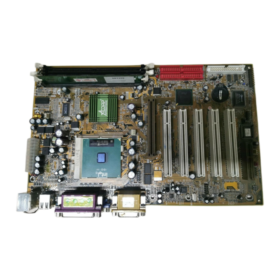
- Page 8 Chaosdr 1 Chaosdr 1 Mnshdranarc Cdrbrhoshnn Mnshdranarc Cdrbrhoshnn Chaosdr 1 Chaosdr 1 Chaosdr 1 Mnshdranarc Cdrbrhoshnn Mnshdranarc Cdrbrhoshnn Mnshdranarc Cdrbrhoshnn 1.4 Motherboard Layout 1.4 Motherboard Layout 1.4 Motherboard Layout 1.4 Motherboard Layout 1.4 Motherboard Layout 1 - 5 1 - 5 1 - 5 1 - 5 1 - 5...
- Page 9 Chaosdr 1 Chaosdr 1 Mnshdranarc Cdrbrhoshnn Mnshdranarc Cdrbrhoshnn Chaosdr 1 Chaosdr 1 Chaosdr 1 Mnshdranarc Cdrbrhoshnn Mnshdranarc Cdrbrhoshnn Mnshdranarc Cdrbrhoshnn 1.4 Motherboard Layout 1.4 Motherboard Layout 1.4 Motherboard Layout 1.4 Motherboard Layout 1.4 Motherboard Layout FAN3 USB1 COM1 Printer Intel 6A815EP1 not onboard Speaker out...
-
Page 10: Cpu Installation
Chaosdr 1 Chaosdr 1 Mnshdranarc Cdrbrhoshnn Mnshdranarc Cdrbrhoshnn Chaosdr 1 Chaosdr 1 Chaosdr 1 Mnshdranarc Cdrbrhoshnn Mnshdranarc Cdrbrhoshnn Mnshdranarc Cdrbrhoshnn 1.5 CPU Installtion 1.5 CPU Installtion 1.5 CPU Installtion 1.5 CPU Installtion 1.5 CPU Installtion The motherboard operates with Socket 370 for Intel PIII processor. -
Page 11: Sdram Installation
Chaosdr 1 Chaosdr 1 Mnshdranarc Cdrbrhoshnn Mnshdranarc Cdrbrhoshnn Chaosdr 1 Chaosdr 1 Chaosdr 1 Mnshdranarc Cdrbrhoshnn Mnshdranarc Cdrbrhoshnn Mnshdranarc Cdrbrhoshnn 1.6 SDRAM Installtion 1.6 SDRAM Installtion 1.6 SDRAM Installtion 1.6 SDRAM Installtion 1.6 SDRAM Installtion DRAM Access Time: 3.3V Unbuffered SDRAM/ PC66/PC100 and PC133 Type required. -
Page 12: Connectors & Jumper Setting
1.7 Connectors & Jumpers Setting 1.7 Connectors & Jumpers Setting 1.7 Connectors & Jumpers Setting 1.7.1 Back Panel I/O Connectors The motherboard provides the following back panel connectors: (Only support by 6A815E1 motherboard) Parallel (Printer) Port MIDI/(GAME) Port (15-pin Female) (25-pin Female) PS/2 Mouse... -
Page 13: Usb Connector: Usb1
COM1/COM2 (Only support by 6A815EP1 M/B) COM2 (Only support by 6A815E1 M/B) 1.7.1.4 Parallel Interface Port Unlike serial ports, parallel interface ports have been standardized and should not present any difficulty interfacing peripherals to your system. Sometimes called a Centronics port, the parallel port is almost exclusively used with printers. -
Page 14: Joystick / Midi Connector
Mnshdranarc Cdrbrhoshnn Mnshdranarc Cdrbrhoshnn 1.7.1.5 VGA Interface Connector: VGA (15 Pin) (Only support by 6A815E1 motherboard) This connector is for output to VGA-compatible devices. 1.7.1.6 Joystick / Midi Connector You can connect a joystick or game pad to this connector. -
Page 15: Floppy Disk Connector: Fdd1
Chaosdr 1 Chaosdr 1 Mnshdranarc Cdrbrhoshnn Mnshdranarc Cdrbrhoshnn Chaosdr 1 Chaosdr 1 Chaosdr 1 Mnshdranarc Cdrbrhoshnn Mnshdranarc Cdrbrhoshnn Mnshdranarc Cdrbrhoshnn 1.7.3 Floppy Disk Connector: FDD1 This connector supports the provided floppy drive ribbon cable. After connecting the single end to the board, connect those two plugs on the other end to the floppy drives. -
Page 16: Cd-Audio-In Connector: Cn1
Chaosdr 1 Chaosdr 1 Mnshdranarc Cdrbrhoshnn Mnshdranarc Cdrbrhoshnn Chaosdr 1 Chaosdr 1 Chaosdr 1 Mnshdranarc Cdrbrhoshnn Mnshdranarc Cdrbrhoshnn Mnshdranarc Cdrbrhoshnn These connectors support cooling fans of 1Amp or less. Orientate the fans so that the heatsink fins allow airflow to go across the onboard heat sink(s) instead of the expansion slots. -
Page 17: Front Panel Connector: J7
Chaosdr 1 Chaosdr 1 Mnshdranarc Cdrbrhoshnn Mnshdranarc Cdrbrhoshnn Chaosdr 1 Chaosdr 1 Chaosdr 1 Mnshdranarc Cdrbrhoshnn Mnshdranarc Cdrbrhoshnn Mnshdranarc Cdrbrhoshnn 1.7.7 Front Panel Connector: J7 FAN3 USB1 COM1 Printer Intel 6A815EP1 not onboard PANEL Connector Speaker out FAN1 Line in GAME1 SPEAK MIC in... -
Page 18: Cmos Function Setting: Jp6
Chaosdr 1 Chaosdr 1 Mnshdranarc Cdrbrhoshnn Mnshdranarc Cdrbrhoshnn Chaosdr 1 Chaosdr 1 Chaosdr 1 Mnshdranarc Cdrbrhoshnn Mnshdranarc Cdrbrhoshnn Mnshdranarc Cdrbrhoshnn Hard Drive LED Connector (HDLED) This connector supplies power to the cabinet IDE activity LED. Read and write activity by devices connected to the Primary or Secondary IDE connectors will cause the LED to light up. -
Page 19: Bios Flash(Jp4)
Chaosdr 1 Chaosdr 1 Mnshdranarc Cdrbrhoshnn Mnshdranarc Cdrbrhoshnn Chaosdr 1 Chaosdr 1 Chaosdr 1 Mnshdranarc Cdrbrhoshnn Mnshdranarc Cdrbrhoshnn Mnshdranarc Cdrbrhoshnn 1.7.9 BIOS Flash: JP4 FAN3 USB1 COM1 Printer Definition Intel Unlocked 6A815EP1 not onboard (Default) Speaker out FAN1 Line in GAME1 MIC in AGP1... -
Page 20: Irda Connector: Ir
Chaosdr 1 Chaosdr 1 Mnshdranarc Cdrbrhoshnn Mnshdranarc Cdrbrhoshnn Chaosdr 1 Chaosdr 1 Chaosdr 1 Mnshdranarc Cdrbrhoshnn Mnshdranarc Cdrbrhoshnn Mnshdranarc Cdrbrhoshnn 1.7.11 IrDA Connector: IR FAN3 USB2 USB1 COM1 Printer Intel 6A815EP1 not onboard Speaker out FAN1 Line in GAME1 MIC in AGP1 LED1 LED1... -
Page 21: Bios Setup
Bhapter 1 Bhapter 1 Bhapter 1 BIOS Settp BIOS Settp BIOS Settp Bhapter 1 Bhapter 1 BIOS Settp BIOS Settp Chapter Introduction This chapter discusses the Award Setup program built into the ROM BIOS. The Setup program allows the user to modify the basic system configuration. - Page 22 Bhapter 1 Bhapter 1 Bhapter 1 BIOS Settp BIOS Settp BIOS Settp Bhapter 1 Bhapter 1 BIOS Settp BIOS Settp APM Support This AWARD BIOS supports Version 1.1&1.2 of the Advanced Power Management(APM) specification.Power management features are implemented via the System Management Interrupt(SMI).
- Page 23 Bhapter 1 Bhapter 1 Bhapter 1 BIOS Settp BIOS Settp BIOS Settp Bhapter 1 Bhapter 1 BIOS Settp BIOS Settp Keystroke Function Up arrow Move to previous item Down arrow Move to next item Left arrow Move to the item on the left (menu bar) Right arrow Move to the item on the right (menu bar) Main Menu: Quit without saving changes...
-
Page 24: Main Menu
Bhapter 1 Bhapter 1 Bhapter 1 BIOS Settp BIOS Settp BIOS Settp Bhapter 1 Bhapter 1 BIOS Settp BIOS Settp 2.1 Main Menu 2.1 Main Menu 2.1 Main Menu 2.1 Main Menu 2.1 Main Menu Once you enter AWARD BIOS CMOS Set up Utility, the Main Menu will appear on the screen. -
Page 25: Integrated Peripherals
Bhapter 1 Bhapter 1 Bhapter 1 BIOS Settp BIOS Settp BIOS Settp Bhapter 1 Bhapter 1 BIOS Settp BIOS Settp Advanced BIOS Features This setup page includes all the items of the BIOS special enchanced features. Advanced Chipset Features This setup page includes all the items of the Chipset special enchanced features. - Page 26 Bhapter 1 Bhapter 1 Bhapter 1 BIOS Settp BIOS Settp BIOS Settp Bhapter 1 Bhapter 1 BIOS Settp BIOS Settp Load Optimized Defaults These settings are more likely to configure a workable computer when something is wrong. If you cannot boot the computer successfully, select the BIOS Setup options and try to diagnose the problem after the computer boots.
-
Page 27: Standard Cmos Features
Bhapter 1 Bhapter 1 Bhapter 1 BIOS Settp BIOS Settp BIOS Settp Bhapter 1 Bhapter 1 BIOS Settp BIOS Settp 2.2 Standard CMOS Features 2.2 Standard CMOS Features 2.2 Standard CMOS Features 2.2 Standard CMOS Features 2.2 Standard CMOS Features This item in the Standard CMOS Setup Menu is divided into 10 categories. -
Page 28: Main Menu Selections
Bhapter 1 Bhapter 1 Bhapter 1 BIOS Settp BIOS Settp BIOS Settp Bhapter 1 Bhapter 1 BIOS Settp BIOS Settp Main Menu Selections This table shows the selections that you can make on the Main Menu. Item Options Description Date Month DD YYYY Set the system,date. - Page 29 Bhapter 1 Bhapter 1 Bhapter 1 BIOS Settp BIOS Settp BIOS Settp Bhapter 1 Bhapter 1 BIOS Settp BIOS Settp Item Options Description Halt On All Errors Select the situation in which you No Errors want the BIOS to stop the POST All, but Keyboard process and notify.
-
Page 30: Advanced Bios Features
Bhapter 1 Bhapter 1 Bhapter 1 BIOS Settp BIOS Settp BIOS Settp Bhapter 1 Bhapter 1 BIOS Settp BIOS Settp 2.3 Advanced BIOS Features 2.3 Advanced BIOS Features 2.3 Advanced BIOS Features 2.3 Advanced BIOS Features 2.3 Advanced BIOS Features ◎... - Page 31 Bhapter 1 Bhapter 1 Bhapter 1 BIOS Settp BIOS Settp BIOS Settp Bhapter 1 Bhapter 1 BIOS Settp BIOS Settp CPU Internal Cache These two categories speed up memory access. However, it depends on CPU/chipset design. Enabled (default) Enabled cache. Disabled Disabled cache.
- Page 32 Bhapter 1 Bhapter 1 Bhapter 1 BIOS Settp BIOS Settp BIOS Settp Bhapter 1 Bhapter 1 BIOS Settp BIOS Settp First/Secondary/Third/Boot Other Device This BIOS attempts to load the operating system from the devices in the sequence selected in these items. The Choices: Floppy, LS120, HDD-0, HDD-1, HDD-2, HDD-3, SCSI, CDROM, Enabled, ZIP, LAN, Disabled.
-
Page 33: Security Option
Bhapter 1 Bhapter 1 Bhapter 1 BIOS Settp BIOS Settp BIOS Settp Bhapter 1 Bhapter 1 BIOS Settp BIOS Settp Typematic Delay (Msec) This option sets the time interval for displaying the first and the second characters. The Choices: 250(default), 500, 750, 1000. Security Option This category allows you to limit access to the system and Setup, or just to Setup. -
Page 34: Advanced Chipset Features
Bhapter 1 Bhapter 1 Bhapter 1 BIOS Settp BIOS Settp BIOS Settp Bhapter 1 Bhapter 1 BIOS Settp BIOS Settp 2.4 Advanced Chipset Features 2.4 Advanced Chipset Features 2.4 Advanced Chipset Features 2.4 Advanced Chipset Features 2.4 Advanced Chipset Features This section allows you to configure the system based on the specific features of the installed chipset. - Page 35 Bhapter 1 Bhapter 1 Bhapter 1 BIOS Settp BIOS Settp BIOS Settp Bhapter 1 Bhapter 1 BIOS Settp BIOS Settp SDRAM CAS Latency / Time 3 (default) Slower SDRAM DIMM Module. Fastest SDRAM DIMM Module. SDRAM Cycle Time Tras/Trc Auto 7/9 (default) Set SDRAM Tras/Trc Cycle time in 7/9 SCLKs.
- Page 36 Bhapter 1 Bhapter 1 Bhapter 1 BIOS Settp BIOS Settp BIOS Settp Bhapter 1 Bhapter 1 BIOS Settp BIOS Settp Memory Hole At 15-16M In order to improve performace, certain space in memory can be reserved for ISA cards. This memory must be mapped into the memory's space below 16MB.
-
Page 37: Integrated Peripherals
Bhapter 1 Bhapter 1 Bhapter 1 BIOS Settp BIOS Settp BIOS Settp Bhapter 1 Bhapter 1 BIOS Settp BIOS Settp Integrated Peripherals Integrated Peripherals 2.5 Integrated Peripherals Integrated Peripherals Integrated Peripherals ◎ ◎ ◎ ◎ ◎ Figure 5. Integrated Peripherals CMOS Setup Utility-Copyright (C) 1984-2001 Award Software Integrated Peripherals On-Chip Primary PCI IDE... - Page 38 Bhapter 1 Bhapter 1 Bhapter 1 BIOS Settp BIOS Settp BIOS Settp Bhapter 1 Bhapter 1 BIOS Settp BIOS Settp On-Chip Primary PCI IDE Enabled (default) Enabled onboard 1st channel IDE port. Disabled Disabled onboard 1st channel IDE port. On-Chip Secondary PCI IDE Enabled (default) Enabled onboard 2nd channel IDE port.
- Page 39 Bhapter 1 Bhapter 1 Bhapter 1 BIOS Settp BIOS Settp BIOS Settp Bhapter 1 Bhapter 1 BIOS Settp BIOS Settp IDE Primary Master UDMA Auto (default) BIOS will automatically detect the IDE HDD Accessing mode. Disabled Disabled. IDE Primary Slave UDMA Auto (default) BIOS will automatically detect the IDE HDD Accessing mode.
- Page 40 Bhapter 1 Bhapter 1 Bhapter 1 BIOS Settp BIOS Settp BIOS Settp Bhapter 1 Bhapter 1 BIOS Settp BIOS Settp Onboard AGP Set Init Display First to onboard AGP. AC 97 Audio Auto (default) BIOS will automatically detect onboard Audio. Disabled Disabled.
- Page 41 Bhapter 1 Bhapter 1 Bhapter 1 BIOS Settp BIOS Settp BIOS Settp Bhapter 1 Bhapter 1 BIOS Settp BIOS Settp Hot Key Power On First you must choose the Ctrl-F1 Power On by Hot Key function Ctrl-F2 then Enter from 1 to 8 Ctrl-F3 characters to set the Hot Key Ctrl-F4...
-
Page 42: Onboard Parallel Port
Bhapter 1 Bhapter 1 Bhapter 1 BIOS Settp BIOS Settp BIOS Settp Bhapter 1 Bhapter 1 BIOS Settp BIOS Settp Onboard Parallel Port This item allows you to select the I/O address with which to access the onboard parallel port controller. Disabled. -
Page 43: Power Management Setup
Bhapter 1 Bhapter 1 Bhapter 1 BIOS Settp BIOS Settp BIOS Settp Bhapter 1 Bhapter 1 BIOS Settp BIOS Settp 2.6 Power Management Setup Power Management Setup Power Management Setup Power Management Setup Power Management Setup The Power Management Setup allows you to configure your system to most effectively save energy while operating in a manner consistent with your own style of computer use. - Page 44 Bhapter 1 Bhapter 1 Bhapter 1 BIOS Settp BIOS Settp BIOS Settp Bhapter 1 Bhapter 1 BIOS Settp BIOS Settp Power Management This option allows you to set each mode individually. When not disabled, each of the ranges are from 1 min. to 1 hr.
- Page 45 Bhapter 1 Bhapter 1 Bhapter 1 BIOS Settp BIOS Settp BIOS Settp Bhapter 1 Bhapter 1 BIOS Settp BIOS Settp HDD Power Down By default, this is “Disabled”, meaning that no matter the mode of the rest of the system, the hard drive will remain ready.
- Page 46 Bhapter 1 Bhapter 1 Bhapter 1 BIOS Settp BIOS Settp BIOS Settp Bhapter 1 Bhapter 1 BIOS Settp BIOS Settp CPU Thermal-Throttling 50.0% (default) Monitor CPU Temp. will cause system to slow down CPU Duty Cycle to 12.5% / 25.0% / 37.5% / 62.5% / 70.5% / 87.5% Resume by Alarm Disabled (default)
-
Page 47: Pnp/Pci Configurations
Bhapter 1 Bhapter 1 Bhapter 1 BIOS Settp BIOS Settp BIOS Settp Bhapter 1 Bhapter 1 BIOS Settp BIOS Settp 2.7 PnP/PCI Configurations PnP/PCI Configurations PnP/PCI Configurations PnP/PCI Configurations PnP/PCI Configurations This section describes configuring the PCI bus system. PCI or Personal Computer Interconnect,is a system which allows I/O devices to operate at speeds nearing the speed of the CPU itself when communicating with its own special... - Page 48 Bhapter 1 Bhapter 1 Bhapter 1 BIOS Settp BIOS Settp BIOS Settp Bhapter 1 Bhapter 1 BIOS Settp BIOS Settp Reset Configuration Data The system BIOS supports the PnP feature so the system needs to record which resource is assigned and proceeds resources from conflict.
-
Page 49: Resources Controlled By
Bhapter 1 Bhapter 1 Bhapter 1 BIOS Settp BIOS Settp BIOS Settp Bhapter 1 Bhapter 1 BIOS Settp BIOS Settp The above settings will be shown on the screen only if “Manual” is chosen for the resources controlled by function. Legacy is the term which signifies that a resource is assigned to the ISA Bus and provides for non-PnP ISA add-on cards. - Page 50 Bhapter 1 Bhapter 1 Bhapter 1 BIOS Settp BIOS Settp BIOS Settp Bhapter 1 Bhapter 1 BIOS Settp BIOS Settp PCI / VGA Palette Snoop Choose Disabled or Enabled. Some graphic controllers which are not VGA compatible take the output from a VGA controller and map it to their display as a way to provide boot information and VGA compatibility.
-
Page 51: Pc Health Status
Bhapter 1 Bhapter 1 Bhapter 1 BIOS Settp BIOS Settp BIOS Settp Bhapter 1 Bhapter 1 BIOS Settp BIOS Settp 2.8 PC Health Status PC Health Status PC Health Status PC Health Status PC Health Status ◎ ◎ ◎ ◎ ◎ Figure 8. PC Health Status CMOS Setup Utility-Copyright (C) 1984-2001 Award Software PC Health Status CPU Warning Temperature... -
Page 52: Cpu Warning Temperature
Bhapter 1 Bhapter 1 Bhapter 1 BIOS Settp BIOS Settp BIOS Settp Bhapter 1 Bhapter 1 BIOS Settp BIOS Settp CPU Warning Temperature(℃ ℃ ℃ ℃ ℃ ) Disabled(default) Disabled. 60 ℃ ℃ ℃ ℃ ℃ / / / / / 140℉ ℉ ℉ ℉ ℉ Monitor CPU Temp.at 60℃/ 140℉. -
Page 53: Frequency/Voltage Control
Bhapter 1 Bhapter 1 Bhapter 1 BIOS Settp BIOS Settp BIOS Settp Bhapter 1 Bhapter 1 BIOS Settp BIOS Settp 2.9 Frequency / Voltage Control Frequency / Voltage Control Frequency / Voltage Control Frequency / Voltage Control Frequency / Voltage Control ◎... -
Page 54: Load Fail-Safe Defaults
Bhapter 1 Bhapter 1 Bhapter 1 BIOS Settp BIOS Settp BIOS Settp Bhapter 1 Bhapter 1 BIOS Settp BIOS Settp 2.10 Load Fail-Safe Defaults 2.10 Load Fail-Safe Defaults 2.10 Load Fail-Safe Defaults 2.10 Load Fail-Safe Defaults 2.10 Load Fail-Safe Defaults When you press <Enter>... -
Page 55: Load Optimized Defaults
Bhapter 1 Bhapter 1 Bhapter 1 BIOS Settp BIOS Settp BIOS Settp Bhapter 1 Bhapter 1 BIOS Settp BIOS Settp 2.11 Load Optimized Defaults 2.11 Load Optimized Defaults 2.11 Load Optimized Defaults 2.11 Load Optimized Defaults 2.11 Load Optimized Defaults When you press <Enter>... -
Page 56: Set Supervisor/User Password
Bhapter 1 Bhapter 1 Bhapter 1 BIOS Settp BIOS Settp BIOS Settp Bhapter 1 Bhapter 1 BIOS Settp BIOS Settp 2.12 Set Supervisor / User Password 2.12 Set Supervisor / User Password 2.12 Set Supervisor / User Password 2.12 Set Supervisor / User Password 2.12 Set Supervisor / User Password ◎... - Page 57 Bhapter 1 Bhapter 1 Bhapter 1 BIOS Settp BIOS Settp BIOS Settp Bhapter 1 Bhapter 1 BIOS Settp BIOS Settp Password Disabled If you select “System” at the Security Option of BIOS Features Setup Menu, you will be prompted for the password every time when the system is rebooted, or any time when you try to enter Setup.
-
Page 58: Save & Exit Setup
Bhapter 1 Bhapter 1 Bhapter 1 BIOS Settp BIOS Settp BIOS Settp Bhapter 1 Bhapter 1 BIOS Settp BIOS Settp 2.13 Save & Exit Setup 2.13 Save & Exit Setup 2.13 Save & Exit Setup 2.13 Save & Exit Setup 2.13 Save &... -
Page 59: Exit Without Saving
Bhapter 1 Bhapter 1 Bhapter 1 BIOS Settp BIOS Settp BIOS Settp Bhapter 1 Bhapter 1 BIOS Settp BIOS Settp 2.14 Exit Without Saving 2.14 Exit Without Saving 2.14 Exit Without Saving 2.14 Exit Without Saving 2.14 Exit Without Saving ◎... -
Page 60: Driver Installation
Introduction There are motherboard drivers and utilities included in ACORP Bonus CD disc. You don't need to install all of them in order to boot your system. But after you finish the hardware installation, you have to install your operation system first (such as windows 98) before you can install any drivers or utilities. -
Page 61: Installing Intel Inf Driver
Chaoser 3 Chaoser 3 Crhver Inrsallashnn Crhver Inrsallashnn Chaoser 3 Chaoser 3 Chaoser 3 Crhver Inrsallashnn Crhver Inrsallashnn Crhver Inrsallashnn 3.2 Installing Intel INF Driver This item install the Intel Chipset Software installation Utility that enables Plug-n-Play INF support for Intel chipset components. - Page 62 Chaoser 3 Chaoser 3 Chaoser 3 Crhver Inrsallashnn Crhver Inrsallashnn Crhver Inrsallashnn Chaoser 3 Chaoser 3 Crhver Inrsallashnn Crhver Inrsallashnn Click "Next". Click "Yes". Click "Next". 3 - 3 3 - 3 3 - 3 3 - 3 3 - 3...
- Page 63 Chaoser 3 Chaoser 3 Crhver Inrsallashnn Crhver Inrsallashnn Chaoser 3 Chaoser 3 Chaoser 3 Crhver Inrsallashnn Crhver Inrsallashnn Crhver Inrsallashnn Click "Finish". Note: Install the Intel INF Driver before installing the Intel Application Accelerator Driver. 3.3 Installing Application Accelerator Driver This item install the Intel Application Accelerator for Microsoft Windows 98/98SE/ME/NT4.0/2000/XP.
- Page 64 Chaoser 3 Chaoser 3 Chaoser 3 Crhver Inrsallashnn Crhver Inrsallashnn Crhver Inrsallashnn Chaoser 3 Chaoser 3 Crhver Inrsallashnn Crhver Inrsallashnn Click "Chipset" Item. Click "Intel Application Accelerator/Ultra ATA Storage Driver" Item. If you choose "Windows 98SE/NT" then you will install Ultra ATA Driver. 3 - 5 3 - 5 3 - 5...
- Page 65 Chaoser 3 Chaoser 3 Crhver Inrsallashnn Crhver Inrsallashnn Chaoser 3 Chaoser 3 Chaoser 3 Crhver Inrsallashnn Crhver Inrsallashnn Crhver Inrsallashnn Click "OK". If you choose "Windows ME/XP/2000" then you will install Intel Application Acceletrator Driver. 3 - 6 3 - 6 3 - 6 3 - 6 3 - 6...
- Page 66 Chaoser 3 Chaoser 3 Chaoser 3 Crhver Inrsallashnn Crhver Inrsallashnn Crhver Inrsallashnn Chaoser 3 Chaoser 3 Crhver Inrsallashnn Crhver Inrsallashnn Click "Finish". (10) Click "OK". 3 - 7 3 - 7 3 - 7 3 - 7 3 - 7...
-
Page 67: Installing Vga Driver
Chaoser 3 Chaoser 3 Chaoser 3 Crhver Inrsallashnn Crhver Inrsallashnn Crhver Inrsallashnn 3.4 Installing VGA Driver (Only support by 6A815E1 motherboard) Intel 815e chipset integrated a 2D/3D graphics acceleration. Click "Driver" Item. Click "VGA" Item. Click "815-0 Graphic Driver" Item. - Page 68 Chaoser 3 Chaoser 3 Chaoser 3 Crhver Inrsallashnn Crhver Inrsallashnn Crhver Inrsallashnn Chaoser 3 Chaoser 3 Crhver Inrsallashnn Crhver Inrsallashnn Click "Next". Click "Yes". 3 - 9 3 - 9 3 - 9 3 - 9 3 - 9...
-
Page 69: Installing Audio Driver
Chaoser 3 Chaoser 3 Crhver Inrsallashnn Crhver Inrsallashnn Chaoser 3 Chaoser 3 Chaoser 3 Crhver Inrsallashnn Crhver Inrsallashnn Crhver Inrsallashnn 3.5 Installing Audio Driver This motherboard comes with an AC97 CODEC and the sound controller is in Intel South Bridge chipset. This item install the Intel Audio for Microsoft Windows 98SE/ME/ NT4.0/2000/XP. - Page 70 Chaoser 3 Chaoser 3 Chaoser 3 Crhver Inrsallashnn Crhver Inrsallashnn Crhver Inrsallashnn Chaoser 3 Chaoser 3 Crhver Inrsallashnn Crhver Inrsallashnn For Win NT , Win 2000, WinXP &Win 9X_ME system. Select your O.S. system. Click "Next". Click "Finish". 3 - 1 1 3 - 1 1 3 - 1 1 3 - 1 1...
Need help?
Do you have a question about the 6A815E1 and is the answer not in the manual?
Questions and answers