Table of Contents
Advertisement
Quick Links
6A815E1/815EP1
User's Manual Version 1.0
The information presented in this publication has been
carefully prepared to ensure reliability ; however, no
responsibility is assumed for inaccuracies.
Specifications are subject to change without notice.
IBM, PC/AT, and PC/XT are trademarks of International Busi-
ness Machines Corporation.
Pentium is a trademark of Intel Corporation
AWARD is a registered trademark of Phoenix Software Inc.
MS-DOS and WINDOWS NT are registered trademarks of
Microsoft Corporation.
Trademarks and/or registered trademarks are the
properties of their respective owners.
Advertisement
Table of Contents

Related Manuals for Acorp 6A815EP1


Summary of Contents for Acorp 6A815EP1
- Page 1 6A815E1/815EP1 User's Manual Version 1.0 The information presented in this publication has been carefully prepared to ensure reliability ; however, no responsibility is assumed for inaccuracies. Specifications are subject to change without notice. IBM, PC/AT, and PC/XT are trademarks of International Busi- ness Machines Corporation.
-
Page 2: Table Of Contents
Table of Contents Chapter 1 Introduction ..........1 How this manual is organized ......1 Package checklist ..........2 Chapter 2 Features ............3 Features of the mainboard ......3 The mainboard layout ....... 6 Chapter 3 Installation ........... 8 System Installation Setups ...... -
Page 3: Chapter 1 Introduction
C h apter 1 Introduction How This Manual is O r ganized This m a nual is divided into the following sections: Chapter 1 Introduction : Manual inform a tion and checklist. Chapter 2 Features : Infor m a tion and Specifications con- cerning this m a inboard. -
Page 4: Package Checklist
Please check that your package is com p lete . Should any item be da m a ged or m i ssing , please contact your retailer i m m e diately. The 6A815E1/6A815EP1 m a inboard. 1 x IDE UDMA100 ribbon cable. -
Page 6: Chapter 2 Features
- G M C H Chipset : Intel 815 support a 66/100/133 FSB -IC H Chipset : Intel IC H 2 Biggest memory capacity : 6A815E1/6A815EP1 is equipped with three DIMM sockets to support (16MB, 32MB, 64MB, 128MB. 256MB) 168 pin 3.3v SDRAM SPD(Special Presence Detect).Maxim u m m e m o ry up to 512MB. - Page 7 BI O S : The m a inboard BIOS provides “Plug & Play” BIOS which detects the peripheral devices and expansion cards of the board auto m a tically. The m a inboard provides a Desktop Managem e nt Interface (DMI) function which records your m a inboard specifications.
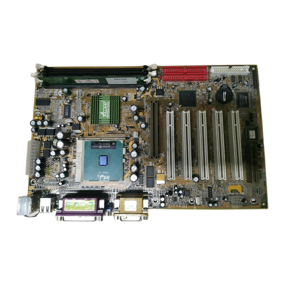
- Page 9 The 6A815E1/6A815EP1 Mainboard layout FAN3 T:RJ-45 B:USB1/2 C O M 1 Printer Intel VG A 6A815EP1 not onboard VG A JACK1 FAN1 JACK2 G A ME1 JACK3 A G P 1 LED1 PCI SLO T 1 PCI SLO T 2...
-
Page 10: Chapter 3 Installation
C h apter 3 Installation Jumper Jumper Refer to page - Real tim e Clock RTC Clean - HD_ LED - Reset Switch - Power LED - Speaker Connector - ATX Power Switch - BIOS Boot Bock Flash Ju m p er - Keyboard Wake up Setting - CNR Card Use Setting 8 / Chapter 3 Installation... - Page 11 Expansion Slot Which page 168 pin DIMM Socket Socket 370 AGP (Accelerator Graphic Port) SLOT PCI SLOT 1,2,3,4,5 -32bits PCI SLOT CNR(Com m u nication and Networking Riser) SLOT19 Connectors Refer to page KB1(DP) - PS/2 Keyboard port KB1(UP) - PS/2 Mouse port. - USB1,2,3,4 Port COM1 - COM 1 serial port (9 pin)
-
Page 12: System Installation Setups
System Installation Setup Before using your co m p uter, you m u st finish the following steps: 1. Set ju m p ers on m a inboard 2. Install SDRAM m o dule. 3. Install the Processor. 4. Connect Ribbon Cables, Cabinet Wires, and Power supply. 5. -
Page 13: Jumper Settings
Jumper Settings Jumpers Several hardware setting are m a de through the use of jum p er caps to connect jum p er pins (Jxx) on the m a inboard. See " Map of the m a inboard" for locations of jum p ers. The ju m p er settings will be described nu m e rically such as [----], [1-2], [2-3] for no connection, connect pins 1 &... - Page 14 JP 6 CMOS Clear T:RJ-45 B:USB1/2 [1-2] Normal (Default) CO M 1 Printer [2-3] E n abled (Clear CMOS ) Intel V G A 6A815EP1 not onboard V G A JACK1 FAN1 JACK2 G A ME1 JACK3 AG P 1...
-
Page 15: System Memory (Dimm Modules)
System Memory ( DIMM Module) This 6A815E1/6A815EP1 m a in board supports three 168 pin DIMM of 16 MB, 32 MB, 64 MB, 128 MB ,256MB to form a m e m o ry size between 16MB to 256MB. The DRAM can be either 45ns,50ns,or60ns SDRAMs. -
Page 16: Dimm Memory Installation
SDRAM DIMM m o dules have different pin con- tacts on each side and therefore have a higher pin density. FAN3 T:RJ-45 B:USB1/2 CO M 1 Printer Intel V G A 6A815EP1 not onboard V G A JACK1 FAN1 JACK2 G A ME1 JACK3 AG P 1... - Page 17 The Dual Inline Me m o ry Module (DIMM) m e m o ry m o dule m u st be 3.3v . You can identify the type of DIMM m o dule by the illustra- tion below: Unbuffered 5.0V Reserved Buffered 3.3V...
-
Page 18: Cpu Installation
CPU will only fit in the orientation as shown. FAN3 T:RJ-45 B:USB1/2 CO M 1 Printer Intel V G A 6A815EP1 not onboard V G A JACK1 FAN1 JACK2 G A ME1 JACK3 AG P 1... -
Page 19: Clearance Requirements
Clearance Requirements To m a intain proper airflow once the processor is installed on the m a inboard, the processor and fan heatsink require certain space clearances. The clearance above the processor m u st be at least 0.3 inches. The clearance on at least 3 of 4 sides of the processor and fan heatsink m u st be at least 0.2 inches. -
Page 20: Easy Over Clock
1. Boostek is a overclocking utility that can overclock step lessly. 2. If you want to overclock , you should , make sure the following: Setup CPU/SDRAM frequency in BIO S . (EX: CPU/SDRAM=66/100, 100/100, 133/100 or 133/133) b. Adjust the FSB of CPU to the frequency you want, then press “Run Setting”... -
Page 21: External Connectors
Serial Port LINE IN FAN3 ATX Po w e r Connector T:RJ-45 B:USB1/2 C O M 1 Printer Intel VG A 6A815EP1 not onboard VG A FAN 1,2,3 JACK1 Connector FAN1 JACK2 G A ME1 JACK3 A G P 1... - Page 22 1. PS/2 K e yboard port This connection is for a standard keyboard using an PS/2 plug (m i ni DIN) . This connector will not allow standard at AT size (large DIN) keyboard plugs. You m a y use a DIN to m i ni DIN adapter on standard AT keyboards.
- Page 23 6. VG A Connectors (15-pin) (O n ly support 6a815e1 motherboard) This connectors support m o nitor. 7. RJ-45 Connector (option) Onboard 10/100MB PCI Fast Ethenet Network. The RJ-45 connectors at the tim e of purchase and is located on top of the USB connectors.The connector allows the m o therboard to connect to a Local Area Network (LAN) through a network hub .
- Page 24 (O n ly FAN1 and FAN3 can detect FAN speed) FAN3 T:RJ-45 B:USB1/2 C O M 1 Printer Intel VG A 6A815EP1 not onboard VG A JACK1 FAN1 FAN1/2/3 CP U Cooling FAN JACK2 G A ME1 JACK3...
- Page 25 FAN3 T:RJ-45 B:USB1/2 CO M 1 Printer Intel V G A 6A815EP1 not onboard V G A JACK1 FAN1 JACK2 G A ME1 JACK3 AG P 1...
- Page 26 12.J6 J6 PANEL Connector SPEAK PW_BN HD_LED PW_LED a. IDE activity LED ( H D -LED) This connector supplies power to the cabinet’s IDE activity LED. Read and write activity by devices connected to the Prim a ry or Secondary IDE connectors will cause the LED to light up. b.
- Page 27 13. ATX Power Supply Connector (20-pin block) - PW1 This connector connects to a ATX power supply. The plug from the power supply will only insert in one orientation because of the different hole sizes. Find the proper orientation and push down fir m l y m a king sure that the pins are aligned.
- Page 28 The 4-pin connectors enable the system to receive the audio output from the CD-ROM. FAN3 T:RJ-45 B:USB1/2 CO M 1 Printer Intel V G A 6A815EP1 not onboard V G A JACK1 FAN1 JACK2 G A ME1 JACK3 AG P 1...
- Page 29 T:RJ-45 B:USB1/2 JP 7 Keyboard Wake up S e tting [1-2] Disabled CO M 1 Printer Intel V G A [2-3] E n abled (Default) 6A815EP1 not onboard Keyboard Boot V G A JACK1 FAN1 JACK2 G A ME1 JACK3...
-
Page 30: Chapter 4 Bios Setup
C h apter 4 Award BIO S Setup Introduction This chapter discusses the Award Setup progra m built into the ROM BIOS. The Setup progra m allows the user to m o dify the basic syste m configuration. This special infor m a tion is then stored in battery-backed RAM so that it retains the setup infor m a tion when the power is turned off. - Page 31 The Award BIOS installed in your com p uter system ’ s ROM (Read Only Mem o ry)is a custom version of an industry standard BIOS. The BIOS provides critical low-level support for standard devices such as disk drives and serial and parallel ports.
- Page 32 PCI Bus Support This AWARD BIOS also supports Version 2.1 of the Intel specification. DRAM Support SDRAM (Synchronous DRAM) are supported. Support CPU This AWARD BIOS supports the Intel Celeron/Copper m i ne PII/PIII Processor. Using Setup In general, you use the arrow keys to highlight item s , press <Enter>to select, use the <PgUp>and <PgDn>keys to change entries, press<F1>for help and press <Esc>to quit.
- Page 33 K e ystroke Function Up arrow Move to previous item Down arrow Move to next item Left arrow Move to the ite m on the left( m e nu bar) Right arrow Move to the ite m on the right( m e nu bar) Main Menu: Quit without saving changes Subm e nus: Exit Current page to the next higher level m e nu...
- Page 34 4.1 Main Menu Once you enter AWARD BIOS CMOS Setup Utility, the Main Menu will appear on the screen. The Main Menu allows you to select fro m several setup function. Use the arrow keys to select am o ng the item s and press<Enter> to accept and enter the sub-m e nu.
- Page 35 Advanced BI O S Features This setup page includes all the ite m s of the BIOS special enchanced features. Advanced Chipset Features This setup page includes all the ite m s of the Chipset special enchanced features. Integrated Peripherals This selection page includes all the item s of the IDE hard drive and Program m e d Input/Output features.
- Page 36 Load O p timized Defaults These settings are m o re likely to configure a workable com p uter when som e thing is wrong. If you cannot boot the com p uter successfully, select the BIOS Setup options and try to diagnose the problem after the com p uter boots.
- Page 37 4.2 Standard CMO S Features This item in the Standard CMOS Setup Menu is divided into 10 categories. Each category includes no, one or m o re than one setup item s . Use the arrow keys to highlight the item and then use the <PgUp>...
- Page 38 Main Menu Selections This table shows the selections that you can m a ke on the Main Menu. Item O p tions Description Date Month DD YYYY Set the syste m , date. Note that the ‘Day’ auto m a tically changes when you set the data.
- Page 39 Item O p tions Description Halt On All Errors Select the situation in which you No Errors want the BIOS to stop the POST All, but Keyboard process and notify. All, but Diskette All, but Disk/Key Base Me m o ry N/A Displays the am o unt of conventional m e m o ry detected during boot up.
- Page 40 4.3 Advanced BI O S Features ◎ ◎ ◎ ◎ ◎ Figure 3. Advanced BI O S Features CMOS Setup Utility-Copyright(C) 1984-2000 Award Software advanced BIOS Features Virus Warning Disabled Item Help CPU Internal Cache Enabled External Cache Enabled Menu Level CPU L2 Cache ECC Checking Enabled Processor Number Feature...
- Page 41 CPU Internal Cache These two categories speed up m e m o ry access. However, it depends on CPU/chipset design. Enabled(default) Enabled cache. Disabled Disabled cache. External Cache This fields allow you to Enable or Disable the CPU’S “Level 2” secondary cache. Caching allows better perfor m a nce.
- Page 42 First/Secondary/Third/Boot O t her Device This BIOS atte m p ts to load the operating syste m fro m the devices in the sequence selected in these ite m s . The Choices: Floppy, LS120, HDD-0, HDD-1, HDD-2, HDD-3, SCSI, CDROM, Enabled, ZIP, LAN, Disabled. Swap Floppy Drive If the syste m has two floppy drives, you can swap the logical drive nam e assignm e nts.
- Page 43 Typematic Delay (Msec) This option sets the ti m e interval for displaying the first and the second characters. The Choices: 250(default), 500, 750, 1000 Security O p tion This category allows you to lim i t access to the system and Setup, or just to Setup.
- Page 45 SDRAM CAS latency Time 3(default) Slower SDRAM DIMM Module. Fastest SDRAM DIMM Module. SDRAM Cycle Time Tras/Trc 7/9(default) Set SDRAM Tras/Trc Cycle ti m e in 7/9 SCLKs. Set SDRAM Tras/Trc Cycle ti m e in 5/7 SCLKs. SDRAM RAS -to- CAS Delay 3(default) Set SDRAM RAS -to- CAS delay 3 SCLKs.
- Page 46 Memory H o le At 15M-16M In order to im p rove perform a ce, certain space in m e m o ry can be reserved for ISA cards. This m e m o ry m u st be m a pped into the m e m o ry's space below 16MB. The Choices: Diasbled(default), Enabled.
- Page 47 4.5 Integrated Peripherals ◎ ◎ ◎ ◎ ◎ Figure 5. Integrated Peripherals CMOS Setup Utility-Copyright(C) 1984-2000 Award Software Integrated Peripherals O n -Chip Primary PCI IDE Enabled Item Help O n -Chip Secondary PCI IDE Enabled IDE Primary Master PIO Auto Menu Level IDE Primary Slave PIO...
- Page 48 O n -Chip Primary PCI IDE Enabled(default) Enabled onboard 1st channel IDE port. Disabled Disabled onboard 1st channel IDE port. O n -Chip Secondary PCI IDE Enabled(default) Enabled onboard 2nd channel IDE port. Disabled Disabled onboard 2nd channel IDE port. IDE Primary Master PI O (for onboard IDE 1st channel) Auto(default) BIOS will autom a tically detect...
- Page 49 IDE Primary Master UDMA Auto(default) BIOS will autom a tically detect the IDE HDD Accessing m o de. Disabled Disabled. IDE Primary Slave UDMA Auto(default) BIOS will autom a tically detect the IDE HDD Accessing m o de. Disabled Disabled. IDE Secondary Master UDMA Auto(default) BIOS will autom a tically detect...
- Page 50 AC 97 Audio Auto(default) BIOS will autom a tically detect onboard Audio. Disabled Disabled. AC 97 Modem Auto(default) BIOS will autom a tically detect onboard Modem . Disabled Disabled. IDE H D D Block Mode Enabled(default) Enabled. Disabled Disabled. Power O n by Function Password Enter from 1 to 7 characters to set the Keyboard Power On...
- Page 51 H o t K e y Power O n First you m u st choose the Ctrl-F1 Power On by Hot Key function Ctrl-F2 then Enter from 1 to 8 Ctrl-F3 characters to set the Hot Key Ctrl-F4 Power On your syste m . Ctrl-F5 Ctrl-F6 Ctrl-F7...
- Page 52 O n board Parallel Port This ite m allows you to select the I/O address with which to access the onboard parallel port controller. Disabled. 378/IR Q 7 . (default) 278/IR Q 5 . 3BC/IR Q 7 . PWR O N After PWR-Fail The Choices: O f f (default), On.
- Page 53 4.6 Power Management Setup The Power Managem e nt Setup allows you to configure your system to m o st effectively save energy while operating in a m a nner consistent with your own style of co m p uter use. ◎...
- Page 54 Power Management This category allows you to select the type (or degree) of power saving and is directly related to the following m o des. 1. HDD Power Down. 2. Doze Mode. 3. Suspend Mode. If you highlight “Press Enter” next to the “Power Manage m e nt”...
- Page 55 Video O f f In Suspend This field deter m i nes when to activate the video off feature for m o nitor power m a nagem e nt. The Choices: Yes(default), No Video O f f Method This determ i nes the m a nner in which the m o nitor is blanked.
- Page 56 H D D Power Down Disabled(default) Disabled. 1 - 15 mins Enabled. Soft-O f f by PWRBTN Pressing the power button for m o re than 4 seconds forces the system to enter the Soft-Off state when the system has “hung”.
- Page 57 Secondary IDE 0/1 Disabled(default) Disabled. Enabled Enabled m o nitor Secondary IDE 0/1 for Green event. FDD,C O M ,LPT Port Disabled(default) Disabled. Enabled Enabled m o nitor FDD, COM, LPT Port. PCI PIR Q [ A-D]# Disabled(default) Ignore PCI PIRQ[A-D]# Active.
- Page 58 4.7 PnP/PCI Configurations This section describes configuring the PCI bus syste m . PCI or Personal Com p uter Interconnect, is a system which allows I/O devices to operate at speeds nearing the speed of the CPU itself when co m m u nicating with its own special co m p onents.
- Page 59 Reset Configuration Data The syste m BIOS supports the PnP feature so the syste m needs to record which resource is assigned and proceeds resources from conflict. Every peripheral device has a node, which is called ESCD. This node records which resources are assigned to it.
- Page 60 The above settings will be shown on the screen only if “Manual” is chosen for the resources controlled by function. Legacy is the ter m which signifies that a resource is assigned to the ISA Bus and provides for non-PnP ISA add-on cards.
- Page 61 PCI / VG A Palette Snoop Choose Disabled or Enabled. So m e graphic controllers which are not VGA com p atible take the output from a VGA controller and m a p it to their display as a way to provide boot inform a tion and VGA com p atibility.
- Page 62 4.8 PC H e alth Status ◎ ◎ ◎ ◎ ◎ Figure 8. PC H e alth Status CMOS Setup Utility-Copyright(C) 1984-2000 Award Software PC Health Status CPU Warning Temperature Disabled Item Help Current System Temp. 39℃/102 ℉ Current CPU Temperature 44℃/111 ℉...
- Page 63 CPU Warning Temperature(℃ ℃ ℃ ℃ ℃ ) Disabled(default) Disabled. 60 ℃ ℃ ℃ ℃ ℃ / / / / / 140℉ ℉ ℉ ℉ ℉ Monitor CPU Te m p .at 60 ℃/ 140℉. 50 ℃ ℃ ℃ ℃ ℃ / / / / / 122℉ ℉ ℉ ℉ ℉ Monitor CPU Te m p .at 50 ℃/ 122℉.
- Page 64 4.9 Frequency / Voltage Control ◎ ◎ ◎ ◎ ◎ Figure 9. Frequency / Voltage Control CMOS Setup Utility-Copyright(C) 1984-2000 Award Software Frequency / Voltage Control Auto Detect DIMM / PCI CLK Disabled Item Help Spread Spectrum Disabled CPU Host/PCI/Spread Spec. Default Menu Level CPU Clock Ratio...
- Page 65 CPU Clock Ratio This option will not be shown if you are using a CPU with the locked ratio. X3/X3.5/X4/X4.5/X5/X5.5/X6/X6.5/X7/X7.5/X8/X8.5/ 9X/9.5X/10X/10.5X/11X/11.5X/12X. Spread Spectrum This function id designed to EMI test only. The Choices: Disabled(default), Enabled. Chapter 4 Aw a rd BIO S Setup / 63...
- Page 66 4.10 Load Fail-Safe Defaults When you press <Enter> on this item , you get a confir m a tion dialog box with a m e ssage si m i lar to: ◎ ◎ ◎ ◎ ◎ Figure 10. Load Fail-Safe Defaults CMOS Setup Utility-Copyright(C) 1984-2000 Award Software Standard CMO S Features...
- Page 67 4.11 Load O p timized Defaults When you press <Enter> on this item , you get a confir m a tion dialog box with a m e ssage si m i lar to: ◎ ◎ ◎ ◎ ◎ Figure 11. Load O p timized Defaults CMOS Setup Utility-Copyright(C) 1984-2000 Award Software Standard CM O S Features...
- Page 68 4.12 Set Supervisor / User Password ◎ ◎ ◎ ◎ ◎ Figure 12. Set Supervisor / User Password CMOS Setup Utility-Copyright(C) 1984-2000 Award Software Standard CMO S Features Frequency/Voltage Control Advanced BIO S Features Load Fail-Safe Defaults Advanced Chipset Features Load O p timized Defaults Integrated Peripherals Set Supervisor Password...
- Page 69 Password Disabled If you select “Syste m ” at the Security Option of BIOS Features Setup Menu, you will be prom p ted for the password every ti m e when the syste m is rebooted, or any tim e when you try to enter Setup. If you select “Setup” at the Security Option of BIOS Features Setup Menu, you will be prom p ted only when you try to enter Setup.
- Page 70 4.13 Save & Exit Setup ◎ ◎ ◎ ◎ ◎ Figure 13. Save & Exit Setup CMOS Setup Utility-Copyright(C) 1984-2000 Award Software Standard CMO S Features Frequency/Voltage Control Advanced BIO S Features Load Fail-Safe Defaults Advanced Chipset Features Load O p timized Defaults Integrated Peripherals Set Supervisor Password Save &...
- Page 71 4.14 Exit Without Saving ◎ ◎ ◎ ◎ ◎ Figure 14. Exit Without Saving CMOS Setup Utility-Copyright(C) 1984-2000 Award Software Standard CM O S Features Frequency/Voltage Control Advanced BI O S Features Load Fail-Safe Defaults Advanced Chipset Features Load O p timized Defaults Integrated Peripherals Set Supervisor Password Exit Without Saving (Y/N)? Y...
- Page 72 Date : Warranty Card/Technical Fault Report M/B Model No.: Vender Serial No. Date of Purchase: Hardw a re Configuration Used : RAM (Brand,MB) Video Card Hard Drive O t her Card Diagnostic Softw a re Used : Fault Description : 70 / Chapter 4 Aw a rd BIO S Setup...
Need help?
Do you have a question about the 6A815EP1 and is the answer not in the manual?
Questions and answers