Table of Contents
Advertisement
Quick Links
6A815EPQ
User's Manual Version 1.0
The information presented in this publication has been
made carefully for reliability; however, no responsibility
is assumed for inaccuracies. Specifications are subject
to change without notice.
IBM, PC/AT, and PC/XT are trademarks of Interna-
tional Business Machines Corporation.
Socket370 is a trademark of Intel Corporation
AWARD is a registered trademark of Phoenix
Software Inc.
MS-DOS and WINDOWS NT are registered trade-
marks of Microsoft Corporation.
Trademarks and/or registered trademarks are the
properties of their respective owners.
i
Advertisement
Table of Contents

Subscribe to Our Youtube Channel
Related Manuals for Acorp 6A815EPQ


Summary of Contents for Acorp 6A815EPQ
- Page 1 6A815EPQ User's Manual Version 1.0 The information presented in this publication has been made carefully for reliability; however, no responsibility is assumed for inaccuracies. Specifications are subject to change without notice. IBM, PC/AT, and PC/XT are trademarks of Interna- tional Business Machines Corporation.
- Page 2 Table of Contents Intrnctctinn Intrnctctinn Intrnctctinn Intrnctctinn Intrnctctinn 1. Mnthdranarc Ddrcriotinn 1. Mnthdranarc Ddrcriotinn 1. Mnthdranarc Ddrcriotinn 1. Mnthdranarc Ddrcriotinn 1. Mnthdranarc Ddrcriotinn 1.1 Fdattrdr 1.1.1 Harcward 1.1.1 Snetward 1.1.3 Attachmdntr 1.1 Mnthdranarc Inrtallatinn 1.1.1 Mnthdranarc Mao 1.1.1 Mnthdranarc Layntt 1.3 Mnthdranarc Cnnndctnrr 1.3.1 Frnnt Pandl Cnnndctnr(J7( 1.3.1 Flnooy Dirk Cnnndctnr(FDD1(...
- Page 3 Table of Contents 1.8 DRAM Inrtallatinn 1.8.1 DIMM 1-19 1.8.1 Hnw tn inrtall a DIMM Mnctld 1-19 1. BINS Sdtto 1. BINS Sdtto 1. BINS Sdtto 1. BINS Sdtto 1. BINS Sdtto 1.1 Main Mdnt 1.1 Stancarc CMNS Fdattrdr 1.3 Acuancdc BINS Fdattrdr 1-10 1.4 Acuancdc Chiordt Fdattrdr 1-14...
- Page 4 Chaosdr 1 Chaosdr 1 Mnshdranarc Cdrbrhoshnn Mnshdranarc Cdrbrhoshnn Chaosdr 1 Chaosdr 1 Chaosdr 1 Mnshdranarc Cdrbrhoshnn Mnshdranarc Cdrbrhoshnn Mnshdranarc Cdrbrhoshnn Introduction System Overview This manual was written to help you start using this product as quickly and smoothly as possbile. Inside, you will find the answers to solve most problems.
- Page 5 -North Bridge System Chipset : Intel 815 B-step support 66/100/133 FSB. -South Bridge System Chipset : Intel ICH2. Biggest memory capacity 6A815EPQ is equipped with three DIMM socket to sup- port (8MB to 512MB) 168 pin 3.3v SDRAM SPD(Special Presence Detect). Maximum memory up to 512MB.
-
Page 6: On-Board Ide
Chaosdr 1 Chaosdr 1 Mnshdranarc Cdrbrhoshnn Mnshdranarc Cdrbrhoshnn Chaosdr 1 Chaosdr 1 Chaosdr 1 Mnshdranarc Cdrbrhoshnn Mnshdranarc Cdrbrhoshnn Mnshdranarc Cdrbrhoshnn On-Board IDE -An IDE controller on the ICH2 chipset provides IDE HDD/ CD-ROM with PIO, Bus Master and Ultra DMA 33/66/ 100 operation modes. - Page 7 Chaosdr 1 Chaosdr 1 Mnshdranarc Cdrbrhoshnn Mnshdranarc Cdrbrhoshnn Chaosdr 1 Chaosdr 1 Chaosdr 1 Mnshdranarc Cdrbrhoshnn Mnshdranarc Cdrbrhoshnn Mnshdranarc Cdrbrhoshnn Suspend and Go : Suspend-to-RAM (STR) provides maximum power sav- ings as an alternative to leaving the computer ON and Quickstart so that you do not have to wait for a long time for system boot.
-
Page 8: Motherboard Installation
Chaosdr 1 Chaosdr 1 Mnshdranarc Cdrbrhoshnn Mnshdranarc Cdrbrhoshnn Chaosdr 1 Chaosdr 1 Chaosdr 1 Mnshdranarc Cdrbrhoshnn Mnshdranarc Cdrbrhoshnn Mnshdranarc Cdrbrhoshnn 1.2 Motherboard Installation 1.2.1 Motherboard Map 1 - 5 1 - 5 1 - 5 1 - 5 1 - 5... -
Page 9: Motherboard Layout
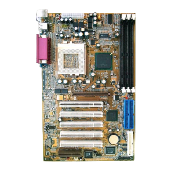
Chaosdr 1 Chaosdr 1 Mnshdranarc Cdrbrhoshnn Mnshdranarc Cdrbrhoshnn Chaosdr 1 Chaosdr 1 Chaosdr 1 Mnshdranarc Cdrbrhoshnn Mnshdranarc Cdrbrhoshnn Mnshdranarc Cdrbrhoshnn 1.2.2 Motherboard Layout FAN3 USB1 COM1 Printer Intel COM2 FAN1 AGP1 LED1 PCI SLOT1 PCI SLOT2 Intel PCI SLOT3 PCI SLOT4 Optional PCI SLOT5 CNR SLOT... -
Page 10: Motherboard Connectors
Chaosdr 1 Chaosdr 1 Mnshdranarc Cdrbrhoshnn Mnshdranarc Cdrbrhoshnn Chaosdr 1 Chaosdr 1 Chaosdr 1 Mnshdranarc Cdrbrhoshnn Mnshdranarc Cdrbrhoshnn Mnshdranarc Cdrbrhoshnn 1.3 Motherboard Connectors FAN3 USB1 COM1 Printer Intel COM2 FAN1 AGP1 LED1 PCI SLOT1 PCI SLOT2 Intel PCI SLOT3 PCI SLOT4 Optional PCI SLOT5 CNR SLOT... -
Page 11: Speaker Connector (Speak)
Chaosdr 1 Chaosdr 1 Mnshdranarc Cdrbrhoshnn Mnshdranarc Cdrbrhoshnn Chaosdr 1 Chaosdr 1 Chaosdr 1 Mnshdranarc Cdrbrhoshnn Mnshdranarc Cdrbrhoshnn Mnshdranarc Cdrbrhoshnn 1.3.1 Front Panel Connector (J7) J7 PANEL Connector SPEAK PW_BN HD_LED PW_LED Speaker Connector (SPEAK) An offboard speaker can be installed onto the motherboard as a manufacturing option.An offboard speaker can be connected to the motherboard at the front pannel connector. -
Page 12: Floppy Disk Connector (Fdd1)
Chaosdr 1 Chaosdr 1 Mnshdranarc Cdrbrhoshnn Mnshdranarc Cdrbrhoshnn Chaosdr 1 Chaosdr 1 Chaosdr 1 Mnshdranarc Cdrbrhoshnn Mnshdranarc Cdrbrhoshnn Mnshdranarc Cdrbrhoshnn 1.3.2 Floppy Disk Connector (FDD1) This connector supports the provided floppy drive ribbon cable. After connecting the single end to the board, connect the two plug on the other end to the floppy drives. -
Page 13: Infrared Connector (Ir)
Chaosdr 1 Chaosdr 1 Mnshdranarc Cdrbrhoshnn Mnshdranarc Cdrbrhoshnn Chaosdr 1 Chaosdr 1 Chaosdr 1 Mnshdranarc Cdrbrhoshnn Mnshdranarc Cdrbrhoshnn Mnshdranarc Cdrbrhoshnn 1.3.4 ATX 20-pin Power Connector (PW1) This connector supports the power button on-board. Using the ATX power supply, functions such as Modem Ring Wake- Up and Soft Power Off are supported on this motherboard . -
Page 14: Back Panel Connectors
Chaosdr 1 Chaosdr 1 Mnshdranarc Cdrbrhoshnn Mnshdranarc Cdrbrhoshnn Chaosdr 1 Chaosdr 1 Chaosdr 1 Mnshdranarc Cdrbrhoshnn Mnshdranarc Cdrbrhoshnn Mnshdranarc Cdrbrhoshnn 1.4 Back Panel Connectors Parallel (Printer) Port (25-pin Fem ale) PS/2 Mouse USB1 COM2 COM1 PS/2 Keyboard (6-pin Fem ale) Serial Port(9-pin Male) 1.4.1 PS/2 Mouse /Keyboard CONN. - Page 15 Chaosdr 1 Chaosdr 1 Mnshdranarc Cdrbrhoshnn Mnshdranarc Cdrbrhoshnn Chaosdr 1 Chaosdr 1 Chaosdr 1 Mnshdranarc Cdrbrhoshnn Mnshdranarc Cdrbrhoshnn Mnshdranarc Cdrbrhoshnn Front Two USB Connectors: USB2 FAN3 USB1 COM1 Printer Intel COM2 FAN1 AGP1 LED1 PCI SLOT1 PCI SLOT2 Intel PCI SLOT3 PCI SLOT4 Optional PCI SLOT5...
-
Page 16: Serial And Parallel Interface Ports
Chaosdr 1 Chaosdr 1 Mnshdranarc Cdrbrhoshnn Mnshdranarc Cdrbrhoshnn Chaosdr 1 Chaosdr 1 Chaosdr 1 Mnshdranarc Cdrbrhoshnn Mnshdranarc Cdrbrhoshnn Mnshdranarc Cdrbrhoshnn 1.5 Serial and Parallel Interface Ports This system comes equipped with two serial ports and one parallel port. Both types of interface ports will be explained in this chapter. -
Page 17: Parallel Interface Port
Chaosdr 1 Chaosdr 1 Mnshdranarc Cdrbrhoshnn Mnshdranarc Cdrbrhoshnn Chaosdr 1 Chaosdr 1 Chaosdr 1 Mnshdranarc Cdrbrhoshnn Mnshdranarc Cdrbrhoshnn Mnshdranarc Cdrbrhoshnn Signal DB9 Pin DB25 Pin Parallel Interface Port Unlike serial ports, parallel interface ports have been standardized and should not present any difficulty interfacing peripherals to your system. -
Page 18: Cpu Installation
Chaosdr 1 Chaosdr 1 Mnshdranarc Cdrbrhoshnn Mnshdranarc Cdrbrhoshnn Chaosdr 1 Chaosdr 1 Chaosdr 1 Mnshdranarc Cdrbrhoshnn Mnshdranarc Cdrbrhoshnn Mnshdranarc Cdrbrhoshnn 1.6 CPU Installation 1.6.1 CPU Installation Procedure: Socket 370 1. Pull the lever sideways away from the socket then raise the lever to a 90-degree angle. -
Page 19: Jumper Setting
Chaosdr 1 Chaosdr 1 Mnshdranarc Cdrbrhoshnn Mnshdranarc Cdrbrhoshnn Chaosdr 1 Chaosdr 1 Chaosdr 1 Mnshdranarc Cdrbrhoshnn Mnshdranarc Cdrbrhoshnn Mnshdranarc Cdrbrhoshnn 1.7 Jumper Setting A jumper has two or more pins that can be covered by a plastic jumper cap, allowing you to select different system options. - Page 20 Chaosdr 1 Chaosdr 1 Mnshdranarc Cdrbrhoshnn Mnshdranarc Cdrbrhoshnn Chaosdr 1 Chaosdr 1 Chaosdr 1 Mnshdranarc Cdrbrhoshnn Mnshdranarc Cdrbrhoshnn Mnshdranarc Cdrbrhoshnn 1.7.2 BIOS Flash: JP4 Assignment Unlocked (Default) Locked 1.7.3 Keyboard wake up Setting: JP7 Assignment Disabled Enabled (Default) Keyboard Boot 1.7.4 CMOS Function Setting: JP6 Assignment Normal (Default)
- Page 21 Chaosdr 1 Chaosdr 1 Mnshdranarc Cdrbrhoshnn Mnshdranarc Cdrbrhoshnn Chaosdr 1 Chaosdr 1 Chaosdr 1 Mnshdranarc Cdrbrhoshnn Mnshdranarc Cdrbrhoshnn Mnshdranarc Cdrbrhoshnn 1.7.5 CNR Card Setting: J8 Assignment Close:secondary (Default) Open :primary 1.7.6 STR LED: LED1 The LED is used for the STR ON/OFF state. 1.7.7 IrDA Connector: IR Pin IR Assignment...
-
Page 22: Dram Installation
Chaosdr 1 Chaosdr 1 Mnshdranarc Cdrbrhoshnn Mnshdranarc Cdrbrhoshnn Chaosdr 1 Chaosdr 1 Chaosdr 1 Mnshdranarc Cdrbrhoshnn Mnshdranarc Cdrbrhoshnn Mnshdranarc Cdrbrhoshnn 1.8 DRAM Installation 1.8.1 DIMM DRAM Access Time: 3.3V Unbuffered SDRAM/ PC66/ PC100 and PC133 Type required. DRAM Type: 8MB, 16MB, 32MB, 64MB, 128MB, 256MB DIMM Module.(168 pin) Bank Memory module... -
Page 23: Bios Setup
Bhapter 1 Bhapter 1 Bhapter 1 BIOS Settp BIOS Settp BIOS Settp Bhapter 1 Bhapter 1 BIOS Settp BIOS Settp 2. BIOS Setup Introduction This chapter discusses the Award Setup program built into the ROM BIOS. The Setup program allows the user to modify the basic system configuration. -
Page 24: Apm Support
Bhapter 1 Bhapter 1 Bhapter 1 BIOS Settp BIOS Settp BIOS Settp Bhapter 1 Bhapter 1 BIOS Settp BIOS Settp APM Support This AWARD BIOS supports Version 1.1&1.2 of the Advanced Power Management(APM) specification. Power management features are implemented via the System Management Interrupt(SMI). - Page 25 Bhapter 1 Bhapter 1 Bhapter 1 BIOS Settp BIOS Settp BIOS Settp Bhapter 1 Bhapter 1 BIOS Settp BIOS Settp Keystroke Function Up arrow Move to previous item Down arrow Move to next item Left arrow Move to the item on the left (menu bar) Right arrow Move to the item on the right (menu bar) Main Menu: Quit without saving changes...
- Page 26 Bhapter 1 Bhapter 1 Bhapter 1 BIOS Settp BIOS Settp BIOS Settp Bhapter 1 Bhapter 1 BIOS Settp BIOS Settp 2.1 Main Menu Once enter AWARD BIOS CMOS Setup Utility, the Main Menu will be shown on the screen. The Main Menu allows you to select from several setup function.
-
Page 27: Pnp/Pci Configuration
Bhapter 1 Bhapter 1 Bhapter 1 BIOS Settp BIOS Settp BIOS Settp Bhapter 1 Bhapter 1 BIOS Settp BIOS Settp Advanced BIOS Features Introduce all the items of the BIOS special enchanced features. Advanced Chipset Features Introduce all the items of the Chipset special enchanced features. -
Page 28: Load Optimized Defaults
Bhapter 1 Bhapter 1 Bhapter 1 BIOS Settp BIOS Settp BIOS Settp Bhapter 1 Bhapter 1 BIOS Settp BIOS Settp Load Optimized Defaults These settings are more likely to configure a workable computer when something is wrong. If you cannot boot the computer successfully, select the BIOS Setup options and try to diagnose the problem after the computer boots. -
Page 29: Standard Cmos Features
Bhapter 1 Bhapter 1 Bhapter 1 BIOS Settp BIOS Settp BIOS Settp Bhapter 1 Bhapter 1 BIOS Settp BIOS Settp 2.2 Standard CMOS Features This item in the Standard CMOS Setup Menu is divided into 10 categories. Each category includes no, one or more than one setup items. -
Page 30: Main Menu Selections
Bhapter 1 Bhapter 1 Bhapter 1 BIOS Settp BIOS Settp BIOS Settp Bhapter 1 Bhapter 1 BIOS Settp BIOS Settp Main Menu Selections This table shows the selections that you can make on the Main Menu. Item Options Description Date Month DD YYYY Set the system,date. - Page 31 Bhapter 1 Bhapter 1 Bhapter 1 BIOS Settp BIOS Settp BIOS Settp Bhapter 1 Bhapter 1 BIOS Settp BIOS Settp Item Options Description Halt On All Errors Select the situation in which you No Errors want the BIOS to stop the POST All, but Keyboard process and notify.
-
Page 32: Advanced Bios Features
Bhapter 1 Bhapter 1 Bhapter 1 BIOS Settp BIOS Settp BIOS Settp Bhapter 1 Bhapter 1 BIOS Settp BIOS Settp 2.3 Advanced BIOS Features ◎ ◎ ◎ ◎ ◎ Figure 3. Advanced BIOS Features CMOS Setup Utility-Copyright (C) 1984-2001 Award Software Advanced BIOS Features Virus Warning Disabled... - Page 33 Bhapter 1 Bhapter 1 Bhapter 1 BIOS Settp BIOS Settp BIOS Settp Bhapter 1 Bhapter 1 BIOS Settp BIOS Settp CPU Internal Cache These two categories speed up memory access. However, it depends on CPU/chipset design. Enabled (default) Enabled cache. Disabled Disabled cache.
- Page 34 Bhapter 1 Bhapter 1 Bhapter 1 BIOS Settp BIOS Settp BIOS Settp Bhapter 1 Bhapter 1 BIOS Settp BIOS Settp First/Secondary/Third/Boot Other Device This BIOS attempts to load the operating system from the devices in the sequence selected in these items. The Choices: Floppy, LS120, HDD-0, HDD-1, HDD-2, HDD-3, SCSI, CDROM, Enabled, ZIP, LAN, Disabled.
-
Page 35: Security Option
Bhapter 1 Bhapter 1 Bhapter 1 BIOS Settp BIOS Settp BIOS Settp Bhapter 1 Bhapter 1 BIOS Settp BIOS Settp Typematic Delay (Msec) This option sets the time interval for displaying the first and the second characters. The Choices: 250(default), 500, 750, 1000. Security Option This category allows you to limit access to the system and Setup, or just to Setup. -
Page 36: Advanced Chipset Features
Bhapter 1 Bhapter 1 Bhapter 1 BIOS Settp BIOS Settp BIOS Settp Bhapter 1 Bhapter 1 BIOS Settp BIOS Settp 2.4 Advanced Chipset Features This section allows you to configure the system based on the specific features of the installed chipset. This chipset manages bus speeds and access to system memory resources, such as DRAM and external cache. - Page 37 Bhapter 1 Bhapter 1 Bhapter 1 BIOS Settp BIOS Settp BIOS Settp Bhapter 1 Bhapter 1 BIOS Settp BIOS Settp SDRAM CAS Latency / Time 3 (default) Slower SDRAM DIMM Module. Fastest SDRAM DIMM Module. SDRAM Cycle Time Tras/Trc Auto 7/9 (default) Set SDRAM Tras/Trc Cycle time in 7/9 SCLKs.
- Page 38 Bhapter 1 Bhapter 1 Bhapter 1 BIOS Settp BIOS Settp BIOS Settp Bhapter 1 Bhapter 1 BIOS Settp BIOS Settp Memory Hole At 15-16M In order to improve performace, certain space in memory can be reserved for ISA cards. This memory must be mapped into the memory's space below 16MB.
-
Page 39: Integrated Peripherals
Bhapter 1 Bhapter 1 Bhapter 1 BIOS Settp BIOS Settp BIOS Settp Bhapter 1 Bhapter 1 BIOS Settp BIOS Settp 2.5 Integrated Peripherals ◎ ◎ ◎ ◎ ◎ Figure 5. Integrated Peripherals CMOS Setup Utility-Copyright (C) 1984-2001 Award Software Integrated Peripherals On-Chip Primary PCI IDE Enabled Item Help... - Page 40 Bhapter 1 Bhapter 1 Bhapter 1 BIOS Settp BIOS Settp BIOS Settp Bhapter 1 Bhapter 1 BIOS Settp BIOS Settp On-Chip Primary PCI IDE Enabled (default) Enabled onboard 1st channel IDE port. Disabled Disabled onboard 1st channel IDE port. On-Chip Secondary PCI IDE Enabled (default) Enabled onboard 2nd channel IDE port.
- Page 41 Bhapter 1 Bhapter 1 Bhapter 1 BIOS Settp BIOS Settp BIOS Settp Bhapter 1 Bhapter 1 BIOS Settp BIOS Settp IDE Primary Master UDMA Auto (default) BIOS will automatically detect the IDE HDD Accessing mode. Disabled Disabled. IDE Primary Slave UDMA Auto (default) BIOS will automatically detect the IDE HDD Accessing mode.
- Page 42 Bhapter 1 Bhapter 1 Bhapter 1 BIOS Settp BIOS Settp BIOS Settp Bhapter 1 Bhapter 1 BIOS Settp BIOS Settp Onboard AGP Set Init Display First to onboard AGP. AC 97 Audio Auto BIOS will automatically detect onboard Audio. Disabled (default) Disabled.
- Page 43 Bhapter 1 Bhapter 1 Bhapter 1 BIOS Settp BIOS Settp BIOS Settp Bhapter 1 Bhapter 1 BIOS Settp BIOS Settp Hot Key Power On First you must choose the Ctrl-F1 Power On by Hot Key function Ctrl-F2 then Enter from 1 to 8 Ctrl-F3 characters to set the Hot Key Ctrl-F4...
-
Page 44: Pwron After Pwr-Fail
Bhapter 1 Bhapter 1 Bhapter 1 BIOS Settp BIOS Settp BIOS Settp Bhapter 1 Bhapter 1 BIOS Settp BIOS Settp Onboard Parallel Port This item allows you to select the I/O address with which to access the onboard parallel port controller. Disabled. -
Page 45: Power Management Setup
Bhapter 1 Bhapter 1 Bhapter 1 BIOS Settp BIOS Settp BIOS Settp Bhapter 1 Bhapter 1 BIOS Settp BIOS Settp 2.6 Power Management Setup The Power Management Setup allows you to configure your system to most effectively save energy while operating in a manner consistent with your own style of computer use. - Page 46 Bhapter 1 Bhapter 1 Bhapter 1 BIOS Settp BIOS Settp BIOS Settp Bhapter 1 Bhapter 1 BIOS Settp BIOS Settp Power Management This option allows you to set each mode individually. When not disabled, each of the ranges are from 1 min. to 1 hr.
-
Page 47: Hdd Power Down
Bhapter 1 Bhapter 1 Bhapter 1 BIOS Settp BIOS Settp BIOS Settp Bhapter 1 Bhapter 1 BIOS Settp BIOS Settp HDD Power Down By default, this is “Disabled”, meaning that no matter the mode of the rest of the system, the hard drive will remain ready. -
Page 49: Pnp/Pci Configurations
Bhapter 1 Bhapter 1 Bhapter 1 BIOS Settp BIOS Settp BIOS Settp Bhapter 1 Bhapter 1 BIOS Settp BIOS Settp 2.7 PnP/PCI Configurations This section describes configuring the PCI bus system. PCI or Personal Computer Interconnect, is a system which allows I/O devices to operate at speeds nearing the speed of the CPU itself when communicating with its own special components. - Page 50 Bhapter 1 Bhapter 1 Bhapter 1 BIOS Settp BIOS Settp BIOS Settp Bhapter 1 Bhapter 1 BIOS Settp BIOS Settp Reset Configuration Data The system BIOS supports the PnP feature so the system needs to record which resource is assigned and proceeds resources from conflict.
-
Page 51: Resources Controlled By
Bhapter 1 Bhapter 1 Bhapter 1 BIOS Settp BIOS Settp BIOS Settp Bhapter 1 Bhapter 1 BIOS Settp BIOS Settp The above settings will be shown on the screen only if “Manual” is chosen for the resources controlled by function. Legacy is the term which signifies that a resource is assigned to the ISA Bus and provides for non-PnP ISA add-on cards. - Page 52 Bhapter 1 Bhapter 1 Bhapter 1 BIOS Settp BIOS Settp BIOS Settp Bhapter 1 Bhapter 1 BIOS Settp BIOS Settp PCI / VGA Palette Snoop Choose Disabled or Enabled. Some graphic controllers which are not VGA compatible take the output from a VGA controller and map it to their display as a way to provide boot information and VGA compatibility.
-
Page 53: Pc Health Status
Bhapter 1 Bhapter 1 Bhapter 1 BIOS Settp BIOS Settp BIOS Settp Bhapter 1 Bhapter 1 BIOS Settp BIOS Settp 2.8 PC Health Status ◎ ◎ ◎ ◎ ◎ Figure 8. PC Health Status CMOS Setup Utility-Copyright (C) 1984-2001 Award Software PC Health Status CPU Warning Temperature Disabled... - Page 54 Bhapter 1 Bhapter 1 Bhapter 1 BIOS Settp BIOS Settp BIOS Settp Bhapter 1 Bhapter 1 BIOS Settp BIOS Settp CPU Warning Temperature(℃ ℃ ℃ ℃ ℃ ) Disabled(default) Disabled. 60 ℃ ℃ ℃ ℃ ℃ / / / / / 140℉ ℉ ℉ ℉ ℉ Monitor CPU Temp.at 60℃/ 140℉.
-
Page 55: Frequency/Voltage Control
Bhapter 1 Bhapter 1 Bhapter 1 BIOS Settp BIOS Settp BIOS Settp Bhapter 1 Bhapter 1 BIOS Settp BIOS Settp 2.9 Frequency / Voltage Control ◎ ◎ ◎ ◎ ◎ Figure 9. Frequency / Voltage Control CMOS Setup Utility-Copyright (C) 1984-2001 Award Software Frequency / Voltage Control Auto Detect DIMM / PCI CLK Disabled... -
Page 56: Load Fail-Safe Defaults
Bhapter 1 Bhapter 1 Bhapter 1 BIOS Settp BIOS Settp BIOS Settp Bhapter 1 Bhapter 1 BIOS Settp BIOS Settp 2.10 Load Fail-Safe Defaults When you press <Enter> on this item, you get a confirmation dialog box with a message similar to: ◎... - Page 57 Bhapter 1 Bhapter 1 Bhapter 1 BIOS Settp BIOS Settp BIOS Settp Bhapter 1 Bhapter 1 BIOS Settp BIOS Settp 2.11 Load Optimized Defaults When you press <Enter> on this item, you get a confirmation dialog box with a message similar to: ◎...
-
Page 58: Set Supervisor/User Password
Bhapter 1 Bhapter 1 Bhapter 1 BIOS Settp BIOS Settp BIOS Settp Bhapter 1 Bhapter 1 BIOS Settp BIOS Settp 2.12 Set Supervisor / User Password ◎ ◎ ◎ ◎ ◎ Figure 12. Set Supervisor / User Password CMOS Setup Utility-Copyright (C) 1984-2001 Award Software Standard CMOS Features Frequency/Voltage Control Advanced BIOS Features... - Page 59 Bhapter 1 Bhapter 1 Bhapter 1 BIOS Settp BIOS Settp BIOS Settp Bhapter 1 Bhapter 1 BIOS Settp BIOS Settp Password Disabled If you select “System” at the Security Option of BIOS Features Setup Menu, you will be prompted for the password every time when the system is rebooted, or any time when you try to enter Setup.
-
Page 60: Save And Exit Setup
Bhapter 1 Bhapter 1 Bhapter 1 BIOS Settp BIOS Settp BIOS Settp Bhapter 1 Bhapter 1 BIOS Settp BIOS Settp 2.13 Save & Exit Setup ◎ ◎ ◎ ◎ ◎ Figure 13. Save & Exit Setup CMOS Setup Utility-Copyright (C) 1984-2001 Award Software Standard CMOS Features Frequency/Voltage Control Advanced BIOS Features... -
Page 61: Exit Without Saving
Bhapter 1 Bhapter 1 Bhapter 1 BIOS Settp BIOS Settp BIOS Settp Bhapter 1 Bhapter 1 BIOS Settp BIOS Settp 2.14 Exit Without Saving ◎ ◎ ◎ ◎ ◎ Figure 14. Exit Without Saving CMOS Setup Utility-Copyright (C) 1984-2001 Award Software Standard CMOS Features Frequency/Voltage Control Advanced BIOS Features... -
Page 62: Auto-Run Menu
Introduction There are motherboard drivers and utilities included in ACORP Bonus CD disc. You don't need to install all of them in order to boot your system. But after you finish the hardware installation, you have to install your operation system first (such as windows 98) before you can install any drivers or utilities. -
Page 63: Installing Intel Inf Driver
Chaoser 3 Chaoser 3 Crhver Inrsallashnn Crhver Inrsallashnn Chaoser 3 Chaoser 3 Chaoser 3 Crhver Inrsallashnn Crhver Inrsallashnn Crhver Inrsallashnn 3.2 Installing Intel INF Driver You can install the Intel inf driver (IDE Bus master (For Windows NT use), Intel ATAPI Vendor Support Driver, Intel AGP, IRQ Routing Driver (For Windows 98 use), Intel Registry (INF) Driver) from the Bonus Pack CD disc auto-run menu. - Page 64 Chaoser 3 Chaoser 3 Chaoser 3 Crhver Inrsallashnn Crhver Inrsallashnn Crhver Inrsallashnn Chaoser 3 Chaoser 3 Crhver Inrsallashnn Crhver Inrsallashnn Click "Disk1" Item. Click "Setup". Click "Next". 3 - 3 3 - 3 3 - 3 3 - 3 3 - 3...
- Page 65 Chaoser 3 Chaoser 3 Crhver Inrsallashnn Crhver Inrsallashnn Chaoser 3 Chaoser 3 Chaoser 3 Crhver Inrsallashnn Crhver Inrsallashnn Crhver Inrsallashnn 3.3 Installing Ultra ATA Driver It is necessary to install Bus Master IDE drive to support ATA hard disk. You can find the Ultra ATA driver from the Bonus Pack CD disc auto-run menu.
-
Page 66: Installing Hardware Monitoring Utility
Chaoser 3 Chaoser 3 Chaoser 3 Crhver Inrsallashnn Crhver Inrsallashnn Crhver Inrsallashnn Chaoser 3 Chaoser 3 Crhver Inrsallashnn Crhver Inrsallashnn 3.4 Installing Hardware Monitoring Utility You can install Hardware Monitoring Utility to monitor CPU temperature, fans and system voltage. The hardware monitoring function is automatically implemented by the BIOS and utility software. - Page 67 Chaoser 3 Chaoser 3 Crhver Inrsallashnn Crhver Inrsallashnn Chaoser 3 Chaoser 3 Chaoser 3 Crhver Inrsallashnn Crhver Inrsallashnn Crhver Inrsallashnn 3.5 Easy Over Clock Driver 1. Boostek is an overclocking utility. 2. If you want to overclock, you should, make sure of the following: a.Setup CPU/SDRAM frequency in BIOS.
- Page 68 Chaoser 3 Chaoser 3 Chaoser 3 Crhver Inrsallashnn Crhver Inrsallashnn Crhver Inrsallashnn Chaoser 3 Chaoser 3 Crhver Inrsallashnn Crhver Inrsallashnn Click "Realtek-AP" Item. Boostekis "Overclock" Run Setting. 3 - 7 3 - 7 3 - 7 3 - 7 3 - 7...
Need help?
Do you have a question about the 6A815EPQ and is the answer not in the manual?
Questions and answers