Table of Contents
Advertisement
Chapter 1
1
Introduction
How This Manual is Organized
This manual is divided into the following sections:
Chapter 1
Introduction : Manual information and checklist.
Chapter 2
Features
Chapter 3
Installation : Instructions on setting up the board.
The mainboard is a high-performance mainboard based on the ad-
vanced Socket 370 microprocessor, the VGA, Audio , PCI Bus and
the VIA 694X chipset.
: Information and Specifications con-
cerning this mainboard.
Chapter 1 Introduction / 1
Advertisement
Table of Contents

Related Manuals for Acorp 6VIA89


Summary of Contents for Acorp 6VIA89
- Page 1 Chapter 1 Introduction How This Manual is Organized This manual is divided into the following sections: Chapter 1 Introduction : Manual information and checklist. Chapter 2 Features : Information and Specifications con- cerning this mainboard. Chapter 3 Installation : Instructions on setting up the board. The mainboard is a high-performance mainboard based on the ad- vanced Socket 370 microprocessor, the VGA, Audio , PCI Bus and the VIA 694X chipset.
-
Page 2: Package Checklist
, please contact with your retailer immediately. The 6VIA89 mainboard. USB2 conector with bracket (option). 1 x IDE UDMA66 ribbon cable. 1 x floppy ribbon cable. 6VIA89 drivers and utilities This user's Manual 2 / Chapter 1 Introduction... - Page 3 Chapter 2 Features Features of the 6VIA89 Mainboard VIA 694X chipset supports 66/100/133MHz FSB, UltraDMA66, AGP4X mode . Supports Intel's processor designed for socket 370 and package in PPGA/ FCPGA. Integrated H/W monitor compensation engine. support "Touch Button Wake up" for soft power on/off and sus- pend mode multifunction.
- Page 4 support Resume by Ring through Modem. Use 168-Pin DIMM modules (supprots Intel PC100/133-compli- ant SDRAMs) x3 . 2 x PCI Bus slots, and 1 x AMR (Audio Modem Riser) slots. 1 x ISA Bus slots. All 2 PCI slots support Master mode. System BIOS support 4 IDE hard disk drivers that don't need device driver for S/W application.
-
Page 5: Installation
Chapter 3 Installation Jumper Jumper Refer to page JBAT1 - CMOS Clear BSEL0-1 - CPU Type selection JCK1-4 - CPU bus frequency selection J3, J4 - On-board AC'97 Selection - AMR Type Selection FAN1 - FAN Connector FAN2 - FAN Connector - IrDA Connector WOL1 - Lan Card Wake Up... -
Page 6: Expansion Slot
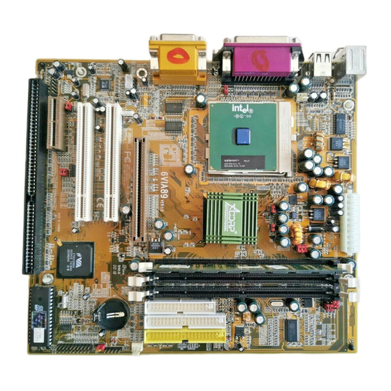
Expansion Slot Which pages PCI SLOT 1,2, -32bits PCI SLOT ISA SLOT 1 -16bits ISA SLOT AMR SLOT1 - Audio Modem Riser Slot Connectors Refer to page - PS/2 Mouse port (UP) - PS/2 AT (mini DIM) Keyboard port (DOWN) 20 COM1 - COM 1 serial port COM2... - Page 7 The 6VIA89 Mainboard Layout B : K / B T: Mouse JCK1 JCK2 JCK3 JCK4 FAN1 BSEL0 BSEL1 COM1 Printer COM2 JACK1 JACK2 GAME1 JACK3 AGP1 FAN2 JWOL1 PCI SLOT1 CDIN1 PCI SLOT2 JBAT1 PANEL1 AMR SLOT ISA SLOT1 BIOS...
-
Page 8: System Installation Setup
System Installation Setup Before using your computer, you must finish the following steps: 1. Set jumpers on mainboard 2. Install SDRAM module. 3. Install the Processor. 4. Connect Ribbon Cables, Cabinet Wires, and Power supply. 5. Install Add on Cards. 6. -
Page 9: Jumper Settings
Jumper Settings Jumpers Several hardware setting are made through the use of jumper caps to connect jumper pins (Jxx) on the mainboard. See " Map of the mainboard" for the locationed the jumpers. The jumper settings will be described numerically such as [----], [1-2], [2-3] for no connection, connect pins 1 &... - Page 10 Real Time Clock (RTC) RAM - JBAT1 : The CMOS RAM is powered by the onboard button cell battery. To clear the RTC data: (1)Turn off your computer, (2) Move this jumper to "2-3Pin Clear Data", (3) Move the jumper back to "Default", (4) Turn on your computer, (5) Hold down <Delete >...
- Page 11 System Memory ( DIMM Module) This 6VIA89 main board supports three 168 pins DIMM of 16 MB, 32 MB, 64 MB, 128 MB ,256MB to form a memory size be- tween 16MB to 256MB. The DRAM can be either Intel PC133-compliant SDRAMs.
-
Page 12: Dimm Memory Installation
DIMM Memory Installation Insert the module (s) as shown. Because the number pins are differ- ent on either side of the breaks,the module will only fit in the orienta- tion as shown. SDRAM DIMM modules have different pin contacts on each side and therefore have a higher pin density. 168 Pin DIMM Socket B : K / B T: Mouse... - Page 13 The Dual Inline Memory Module (DIMM) memory module must be 3.3v Extended Data Output (EDO) DRAM or SDRAM. You can identify the type of DIMM module by the illustration below: Unbuffered 5.0V Reserved Buffered 3.3V Voltage Key Position DRAM Key Position 168 Pin DRAM DIMM Notch Key Definitions The notch on the DIMM module will shift between left, center, or right to identify the type and also to prevent the wrong type to be...
-
Page 14: Cpu Installation
CPU Installation The motherboard provides a ZIF socket 370. The CPU that came with the motherboard should have a fan attached to it to prevent over- heating . If this is not the case then purchase a fan before you turn on your system. - Page 15 CPU Type Selection -BSEL0, BSEL1 Current PCI bus in limited to 33MHz, socket370 Celeron processors limited to 66MHz, and SDRAM limited to the DIMM type 66/100/ 133MHz. (66MHz SDRAM is not supported on this motherboard.) Other settings are for experienced users only. NOTE: Most of the CPU frequency are locked by the manufacturer.
- Page 16 CPU External (Bus) Frequency Selection -JCK1, JCK2, JCK3, JCK4 The JCK1~4 jumpers is used to set PCI and CPU external bus clock. C L K P C I J C K 1 J C K 2 J C K 3 J C K 4 133.3 33.3...
- Page 17 Audio/Modem Riser (AMR) Function Selection : J2 Primary Secondary K / B B: Mouse JCK1 JCK2 JCK3 JCK4 FAN1 BSEL0 BSEL1 COM1 Printer COM2 JACK1 JACK2 GAME1 JACK3 AGP1 FAN2 JWOL1 PCI SLOT1 CDIN1 PCI SLOT2 JBAT1 PANEL1 AMR SLOT ISA SLOT1 BIOS Onboard AC'97 Function Selection : J3, J4...
-
Page 18: Clearance Requirements
Clearance Requirements To maintain proper airflow once the processor is installed on the mainboard, the processor and fan heatsink require certain space clearances. The clearance above the processor must be at least 0.3 inch. The clearance on at least 3 of 4 sides of the processor and fan heatsink must be at least 0.2 inch. -
Page 19: External Connectors
EXTERNAL CONNECTORS Both Ribbon cable and Connectors on board are with direction signs to avoid that user insert wrong direction. The ribbon cables should always be connected with the red stripe on the pin 1 of side of the connector. MIDI/(GAME) Port Parallel (Printer) Port (15-pin Female) - Page 20 1. PS/2 AT Keyboard port This connection is for a standard keyboard using an PS/2 plug (mini DIN) . This connector will not allow standard at AT size (large DIN) keyboard plugs. You may use a DIN to mini DIN adapter on standard AT keyboards.
- Page 21 the wiring and plug may be different. The red wire should be positive, while the black should be ground. Connect the fan’s plug to the board taking into consideration the polarity of the this connector. B : K / B T: Mouse JCK1 JCK2...
- Page 22 install two hard disks, you must configure the second drive to Slave mode by setting its jumper settings. BIOS now supports SCSI device or IDE CD-ROM boot up (see "HDD Sequence SCSI/ IDE First" & "Boot Sequence" in the BIOS Features Setup of the BIOS SOFTWARE) (Pin 20 is removed to prevent inserting in the wrong orientation when using ribbon cables with pin 20 plugged) You may configure two hard disks to be both Masters using...
- Page 23 connect a ribbon cable from the module to the motherboard according to the pin definitions. 10. PANEL1 PANEL1 Connector PW_LED PW_BN HD_LED SPEAK a. IDE activity LED (HD-LED) This connector supplies power to the cabinet’s IDE activity LED. Read and write activity by devices connected to the Primary or Secondary IDE connectors will cause the LED to light up.
- Page 24 d. Reset Switch Lead (RST) This 2-pin connector connects to the case-mounted reset switch for rebooting your computer without having to turn off your power switch. This is a preferred method of rebooting in order to pro- long the life of the system's power supply. e.
- Page 25 Description Description 3.3V 3.3V PW-OK 5VSB 3.3V -12V PS-ON 12. CD Audio Connector- CDIN1 The 4-pin connectors enable the system to receive the audio output from the CD-ROM. Description CD-R CD-L B : K / B T: Mouse JCK1 JCK2 JCK3 JCK4 FAN1...
- Page 26 13. Wake Up On LAN : WOL1 This connector connects LAN cards and a Wake On LAN output. When the system is in soft-off mode LAN activity will power on the system. Wake-On-LAN Connector Description 5VSB SENSOR B : K / B T: Mouse JCK1 JCK2...
- Page 27 Guarantee Sheet/Technical Fault Report M/B Model No.: Vender Serial No. Date of Purchasing: Hardware Configuration Used : Video Card Hard Drive Other Card Diagnostic Software Used : Fault Description : Technical Support : WWW : www.acorp.com.tw fae@acorp.com.tw Chapter 3 Installation / 27...
Need help?
Do you have a question about the 6VIA89 and is the answer not in the manual?
Questions and answers