Advertisement
Quick Links
Advertisement

Related Manuals for SIMPLIHOME Sidney AXCSDY-01


Summary of Contents for SIMPLIHOME Sidney AXCSDY-01
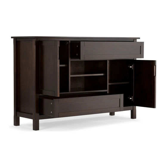
- Page 1 Sidney / Fleming / Dressler 54 Inch Tall TV Stand Model # AXCSDY-01...
- Page 2 Great quality is a right. Thank you for shopping with Simpli Home, America's top brand for high-value furniture. It's time to register your product warranty. It's quick and easy. And you'll be happy you did. ü Activate your 1-year warranty ü...
- Page 3 Review your product and collect rewards! Thank you for your purchase! We hope you enjoy it. We’d love your feedback. Please share a review and get instant rewards! simpli-home.com/product-review Share photos and get your cash back! Send us images or share them on social and qualify for instant rewards.
- Page 4 For Fastest Customer Service: Open your phone’s camera. Point your phone’s camera at the QR code to scan. Click on the pop up. You’ll be taken to our customer service page. Fill the form with your order information and issue. Submit form.
-
Page 5: Safety Information
IMPORTANT : Please read this manual carefully before beginning assembly of this product. Keep this manual for future reference. Safety Information CAUTION: Injuries and damage can occur from furniture tip over if product is not properly anchored to the wall. Use the Furniture Anti-Tipping Restraint provided with the product. -
Page 6: Care And Maintenance
Care & Maintenance This furniture is designed for indoor use. Perhaps the greatest environmental damage to wood furniture comes from wide swings in relative humidity (RH) in our homes. Wood absorbs and desorbs water as relative humidity rises and falls, and in doing so it swells and shrinks. Making matters worse, it expands and contracts unequally along different grain directions. -
Page 7: Maximum Load 25 Lbs
WARNING The maximum diagonal CRT television screen size is 25 inch to 27 inch (63.50 cm to 68.58 cm). For use with televisions weighing 200 lbs or less. Using larger or heavier televisions may cause instability or tip over which can lead to serious injury or even death. - Page 8 Pre-Assembly Information Model # AXCSDY-01 Part Description LEFT SIDE RIGHT SIDE QTY 1 QTY 1 QTY 1 LEFT DIVIDER RIGHT DIVIDER TOP FRAME QTY 1 QTY 1 QTY 1 CENTRE SHELF BOTTOM SHELF SIDE SHELF QTY 1 QTY 1 QTY 2 CENTRE SHELF LEFT DOOR RIGHT DOOR...
- Page 9 Pre-Assembly Information Model # AXCSDY-01 Part Description Warning Label LEFT BACK PANEL RIGHT BACK PANEL TOP & BOTTOM BACK PANEL QTY 1 QTY 1 QTY 2 LEFT DRAWER SIDE CENTRE BACK PANEL DRAWER FRONT QTY 2 QTY 1 QTY 2 RIGHT DRAWER SIDE DRAWER BACK DRAWER BOTTOM...
- Page 10 Pre-Assembly Information Model # AXCSDY-01 Hardware Description CAM LOCK PIN ALLEN KEY SCREW WOOD DOWEL CAM LOCK M6 X 30mm M8 X 30mm ALLEN KEY QTY 32 SETS QTY 26 QTY 18 QTY 1 PHILLIPS SCREW PHILLIPS SCREW ROUND HEAD M3 X 15mm M4 X 15mm SHELF SUPPORT...
- Page 11 Components - Key Diagram Model # AXCSDY-01...
- Page 12 Assembly Model # AXCSDY-01 Step 1 1. Attach 6 Cam Lock Pins 2 to pre-drilled holes at back of Drawer Front M . 2. Align Cam Lock Pins with pre-drilled holes and attach Drawer Sides NL , NR and Drawer Bottom Supports Q . 3.
- Page 13 Assembly Model # AXCSDY-01 Step 3 1. Attach 2 Cam Lock Pins 2 to pre-drilled holes at Drawer Back O . Step 4 1. Align Cam Lock Pins on Drawer Back O with pre-drilled holes on Drawer Bottom Supports Q . 2.
- Page 14 Assembly Model # AXCSDY-01 Step 5 1. Insert 2 Dowels 3 into pre-drilled holes on Left Divider D . 2. Use rubber mallet to tap Dowels 3 into bottom of holes securely. 1/2 length of Dowels should be exposed. 3. Attach 2 Cam Lock Pins 2 to Left Divider D using guide holes. 4.
- Page 15 Assembly Model # AXCSDY-01 Step 6 1. Attach 3 Cam Lock Pins 3 to Right Divider E using guide holes. 2. Align Cam Lock Pins with pre-drilled holes on Centre Shelf G . 3. Insert 3 Cam Locks 2 into pre-drilled holes on Centre Shelf G . 4.
- Page 16 Assembly Model # AXCSDY-01 Step 7 1. Insert 2 Dowels 3 into pre-drilled holes on each Left Divider D and Right Divider E . 2. Use rubber mallet to tap Dowels 3 into bottom of holes securely. 1/2 length of Dowels should be exposed.
- Page 17 Assembly Model # AXCSDY-01 Step 8 1. Insert 2 Dowels 3 into pre-drilled holes on Right Divider E . 2. Use rubber mallet to tap Dowels 3 into bottom of holes securely. 1/2 length of Dowels should be exposed. 3. Attach Right Divider E to Bottom Shelf H using 3 Allen Key Screws 1 . 4.
- Page 18 Assembly Model # AXCSDY-01 Step 9 1. Insert 4 Dowels 3 into pre-drilled holes on Bottom Shelf H and Top Frame F ( 2 Dowels on each part ) . 2. Use rubber mallet to tap Dowels 3 into bottom of holes securely. 1/2 length of Dowels should be exposed.
- Page 19 Assembly Model # AXCSDY-01 Step 10 1. Insert 2 Dowels 3 into pre-drilled holes on Bottom Shelf H . 2. Use rubber mallet to tap Dowels 3 into bottom of holes securely. 1/2 length of Dowels should be exposed. 3. Attach 6 Cam Lock Pins 2 to Left Side C using guide holes. 4.
- Page 20 Assembly Model # AXCSDY-01 Step 11 1. Insert 4 Dowels 3 into pre-drilled holes on Right Side B and Left Side C . 2. Use rubber mallet to tap Dowels 3 into bottom of holes securely. 1/2 length of Dowels should be exposed. 3.
- Page 21 Assembly Model # AXCSDY-01 Note: Step 12 Warning Label 1. Attach Back Panels LL , LR , L1 , L2 to back frame of TV Stand using 38 Phillips Screws Round Head 5 through pre-drilled holes. 2. Use Phillips Screwdriver to tighten screws.
- Page 22 Assembly Model # AXCSDY-01 Step 13 & K 1. Attach Adjustable Hinges 10 to Doors KL , KR using Phillips Screws 9 into guide holes on Doors KL , KR . 2. Attach Adjustable Hinges on Doors KL , KR to Sides C , B using Phillips Screws 9 into guide holes on Sides C , B .
-
Page 23: Important Note
Assembly Model # AXCSDY-01 IMPORTANT NOTE: Tighten the Screw marked II to fasten hinge. The door may need to be adjusted so that all the spaces between the door and the unit sides are equal. To adjust, follow instructions: 1. Side adjustment 4 mm To move the door towards the side panel, loosen screw I and tighten screw II . - Page 24 Assembly Model # AXCSDY-01 Step 14 1. Keep your position 0.5 m ( 20 inch ) away from the glider! 2. Slightly push the rail backward to unlock. Hold the rail while it is pulled out automatically. Important Note: While push the rail backward, do not release the rail. Instead please hold it in order to avoid the propulsive force by its springs.
- Page 25 Assembly Model # AXCSDY-01 Step 15 Back view 1. Place the drawer on top of 2 gliders. 2. Push the drawer along the gliders until the 2 holes at the rear of the back panel ( of drawer box ) inserted into the hook at back of the rails. 3.
- Page 26 Assembly Model # AXCSDY-01 Step 16 Lock position ( Both side of drawer ). 1. Push lock c on the rails to lock the rail and the drawer.
- Page 27 Assembly Model # AXCSDY-01 Step 17 1. After completing the assemble of drawer box, if it's not well positioned with the front of drawer frame, pls follow the below steps: - Unlock the lock c by pulling it out. - Lift up the front of drawer box. - Adjusting the cog-wheel d to lower / higher the side panel to suitable position.
- Page 28 Assembly Model # AXCSDY-01 Step 18 1. Repeat Step 14-17 for the second Drawer.
- Page 29 Assembly Model # AXCSDY-01 Step 19 1. Use 4 Shelf Supports 6 for each Side Shelf I and Centre Shelf J in desired location. 2. 2 Shelf Supports 6 may be used on back top of each Side Shelf I and Centre Shelf J as a tipping restraint.
- Page 30 Furniture Tip Over Restraint Assembly WARNING Serious or fatal crushing injuries can occur from furniture tip-over. If the furniture tip over restraint kit is not in the box, please contact our customer service department in order to obtain another kit before using the furniture. NOTE: The screwdriver is not included in the hardware pack.
- Page 31 Furniture Anti-Tipping Restraint Instructions Attach one of the mounting brackets securely to the back edge of the furniture. Use the shorter screw. Determine where furniture is to be placed and mark location on the wall for mounting bracket screw hole approximately 2 inches below the bracket mounted to the furniture.
Need help?
Do you have a question about the Sidney AXCSDY-01 and is the answer not in the manual?
Questions and answers