Table of Contents
Advertisement
Quick Links
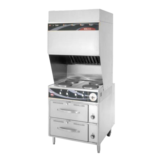
Model WV-4HSRW
IMPORTANT: DO NOT DISCARD THIS MANUAL
This manual is considered to be part of the appliance and is to be given to the OWNER or
MANAGER of the restaurant, or to the person responsible for TRAINING OPERATORS of
this appliance. Additional manuals are available from your WELLS DEALER.
THIS MANUAL MUST BE READ AND UNDERSTOOD BY ALL PERSONS USING OR
INSTALLING THIS APPLIANCE. Contact your WELLS DEALER if you have any
questions concerning installation, operation or maintenance of this equipment.
2M-303903
p/n
REV G (04-22)
WELLS BLOOMFIELD, LLC
265 Hobson St. • Smithville, TN 37166
telephone: (800) 264-7827
wells-mfg.com
OWNERS MANUAL
WV-4H SERIES
HOTPLATE
COOKTOP
with
UNIVERSAL
HOOD
MODELS:
WV4HF
WV4HFRW
WV4HS
WV4HSRW
Includes
INSTALLATION
USE & CARE
EXPLODED VIEW
PARTS LIST
WIRING DIAGRAM
504
13
M504
0130
Advertisement
Table of Contents

Related Manuals for Wells WV-4H Series


Summary of Contents for Wells WV-4H Series
- Page 1 Additional manuals are available from your WELLS DEALER. THIS MANUAL MUST BE READ AND UNDERSTOOD BY ALL PERSONS USING OR INSTALLING THIS APPLIANCE. Contact your WELLS DEALER if you have any questions concerning installation, operation or maintenance of this equipment.
-
Page 2: Warranty
THE FOLLOWING WILL NOT BE COVERED UNDER WARRANTY. products to be free from defects in material or workmanship, under normal Wells’ sole obligation under this warranty is limited to either repair or and proper use and maintenance service as specified by Wells and upon... -
Page 3: Table Of Contents
CUSTOMER SERVICE DATA ..... 41 INTRODUCTION Thank You for purchasing this Wells Manufacturing appliance. Proper installation, professional operation and consistent maintenance of this appliance will ensure that it gives you the very best performance and a long, economical service life. -
Page 4: Features & Operating Controls
FEATURES & OPERATING CONTROLS Fig. 1 Ventilator Section Operating Features & Controls... - Page 5 FEATURES & OPERATING CONTROLS (continued) VENTILATOR SECTION ITEM DESCRIPTION COMMENT FIRE SUPPRESSION AGENT TANK (1.5 gal.) Container for Ansulex™ Low-pH liquid fire suppression liquid. ADJUSTABLE (FRONT) LEG Allows the unit to be leveled. Allows the unit to be easily positioned by lifting the front of the unit RIGID (REAR) CASTER slightly.
- Page 6 FEATURES & OPERATING CONTROLS (continued) Fig. 2 Ventilator Section Controls & Indicator Lights Fig. 3 Cooktop Section Controls & Indicator Lights Fig. 4 Cooktop & Warmer Drawer Operating Features & Controls...
- Page 7 FEATURES & OPERATING CONTROLS (continued) ITEM DESCRIPTION COMMENT VENTILATOR SECTION CONTROLS Energizes blower motor. If, after 10 seconds, proper POWER SWITCH conditions are met, cooktop is energized. POWER ON INDICATOR GREEN. Glows when POWER switch is ON. CHECK FILTERS ALARM AMBER.
-
Page 8: Precautions & General Information
PRECAUTIONS AND GENERAL INFORMATION NOTE: Fire suppression system and all associated components WARNING: must only be serviced by an authorized Ansul® Distributor. All setup, charging, repair and/or adjustment of the fire suppression system must ELECTRIC be performed by an Authorized Ansul® Distributor ONLY. SHOCK HAZARD IMPORTANT: If a remote pull station is installed, both rear casters All servicing requiring... -
Page 9: Agency Listing Information
Wells service agent. Parts supplied by others will void your warranty and may not provide safe operation. The Ventless Cooking System™ hood is designed as part of a WELLS cooktop appliance only. No other use of this product is authorized by the manufacturer or its agents. -
Page 10: Installation
INSTALLATION UNPACKING & INSPECTION NOTE: DO NOT discard the carton or other packing Carefully remove the appliance from the carton. Remove all protective materials until you have plastic film, packing materials and accessories from the appliance inspected the appliance for before connecting electrical power or otherwise performing any hidden damage and tested it installation procedure. - Page 11 INSTALLATION (continued) SERVICE TECHNICIAN INSTALLATION NOTES IMPORTANT! An Ansul® technician must charge and arm the fire suppression system Verify that this VENTILATOR before the ventilator blower will operate. See page 10. and food cooking equipment installation is in compliance Installation and start up must be performed by an Authorized with the specifications listed Installation Company.
- Page 12 (i.e. remove rear casters and replace with legs). Additional legs may be ordered through an Authorized Wells Service Agency. See page 25. 2. The FIRE SUPPRESSION SYSTEM is comprised of a pressurized cartridge &...
- Page 13 GREASE BAFFLE: If the GREASE BAFFLE is not in place, the Use only genuine Wells parts and CHECK FILTERS indicator will glow. filters, call (800) 264-7827 or your To install the GREASE BAFFLE: Slide the grease baffle up into the authorized Wells service agent.
- Page 14 INSTALLATION (continued) WARNING GREASE TROUGH AND GREASE CUP INSTALLATION SLIP / FALL Install the GREASE TROUGH into the brackets below the grease HAZARD baffle. SPILLED OIL Install the GREASE CUP on the right side of the unit, directly below the grease trough. ROLL WARMER INSTALLATION Be sure roller catches (inside warmer cavity) are in the open position.
-
Page 15: Operation
OPERATION VENTILATOR OPERATION CAUTION: Press the VENTILATOR POWER switch to ON. The green HOT SURFACE VENTILATOR POWER light will glow and the blower fan will start. After a short time, if all filters are sensed as being in position and Exposed surfaces can be hot not clogged, the cooktop will be energized. - Page 16 OPERATION (continued) HOTPLATE COOKTOP OPERATION CAUTION: GENERAL OPERATIONAL NOTES HOT SURFACE Carefully read the description of the hotplate operation on the specification sheet. Exposed surfaces can be hot DO NOT attempt to perform any maintenance or service unless the to the touch and may cause hotplate is disconnected from electrical power.
- Page 17 Moist heat with pans: enable you to determine the This Wells warmer is designed to accommodate any combination temperature control and air of standard-size, steam table pans. vent settings best suited to your operation.
- Page 18 OPERATION (continued) DRAWER WARMER OPERATION (when provided) ITEM DESCRIPTION PROCESS Key: Press to view actual temperature of cavity. 4 Character LED Display: Normally shows SETPOINT temperature. ºF or ºC Indicator: Glows to indicate if unit is configured for degrees Fahrenheit or degrees Celsius. LOAD Indicator: Glows when heating element is energized.
-
Page 19: Cleaning Instructions
CLEANING INSTRUCTIONS HOTPLATE COOKTOP DAILY CLEANING CAUTION: ELECTRIC PREPARATION Disconnect appliance from electric power SHOCK HAZARD Allow to cool before cleaning Disconnect appliance from FREQUENCY Daily electric power before cleaning. TOOLS Warm water and a mild detergent Soft clean cloth or sponge Plastic scouring pad, plastic scraper CAUTION: HOT SURFACE... - Page 20 CLEANING INSTRUCTIONS (continued) VENTILATOR WEEKLY CLEANING CAUTION: ELECTRIC PREPARATION: Disconnect appliance from electric power SHOCK HAZARD Allow to cool before cleaning Disconnect appliance FREQUENCY: Weekly from electric power before cleaning. TOOLS: Warm water and a mild detergent Soft clean cloth or sponge Bristle brush CAUTION: Container for disposal of grease...
- Page 21 CLEANING INSTRUCTIONS (continued) VENTILATOR MONTHLY CLEANING CAUTION: ELECTRIC PREPARATION: Disconnect appliance from electric power SHOCK HAZARD Allow to cool before cleaning Disconnect appliance from FREQUENCY: Monthly electric power before cleaning. TOOLS: Warm water and a mild detergent Soft clean cloth or sponge CAUTION: Plastic scouring pad, plastic scraper HOT SURFACE...
- Page 22 CLEANING INSTRUCTIONS (continued) CAUTION: DRAWER WARMER DAILY CLEANING ELECTRIC PRECAUTIONS: Turn control knob to OFF. SHOCK HAZARD Allow drawers to cool before proceeding. Remove drawer pans and Humitrol racks. Disconnect appliance from electric power before FREQUENCY: Minimum -Daily cleaning. TOOLS: Warm water and mild detergent Clean cloth or sponge CAUTION:...
-
Page 23: Maintenance Schedules
MAINTENANCE SCHEDULES USE AND MAINTENANCE 1. 6-MONTH MAINTENANCE (MUST BE PERFORMED BY AN SHALL BE IN ACCORDANCE AUTHORIZED ANSUL® DISTRIBUTOR ONLY): WITH THE STANDARD FOR Inspect and test total operation including FIRE DAMPER and VENTILATION CONTROL all SAFETY INTERLOCKS. AND FIRE PROTECTION OF COMMERCIAL COOKING All FIRE SUPPRESSION SYSTEM actuation components OPERATIONS, N.F.P.A 17A &... -
Page 28: Troubleshooting Suggestions
NOTE: There are no user serviceable components in the appliance. A. In all cases of damage or component malfunction, contact your Authorized Wells Service Agency for repairs. B. For service of the fire suppression system, contact an Authorized Ansul® Distributor. -
Page 29: Ansul® Components
PARTS BREAKDOWN for ANSUL® COMPONENTS... -
Page 30: Exploded View & Parts List
EXPLODED VIEW & PARTS LIST HOOD CABINET COMPONENTS... - Page 31 EXPLODED VIEW & PARTS LIST HOOD CABINET COMPONENTS Model: WV4H Hood Cabinet Components Fig No. Part No Description Application 2V-301187 DAMPER 2E-305098 LIGHT HOUSING VCS HOOD NEW 2S-305100 LIGHT BULB/100W-230V, FROSTED 2Q-305099 GLASS GLOBE VCS HOOD M3-304405 TRAY GREASE DRIP HOOD 5E-20804 CASTER ASSY 2FIX, 2SWVL 5M-22649...
- Page 32 EXPLODED VIEW & PARTS LIST HOOD ELECTRICAL & VACUUM COMPONENTS...
- Page 33 EXPLODED VIEW & PARTS LIST HOOD ELECTRICAL & VACUUM COMPONENTS Model: WV4H Hood Electrical & Vacuum Components Fig No. Part No Description 2U-302584 BLOWER ASSY UNIVERSAL N1-307594 TUBING ASSY VACUUM UNIV 2K-37748X FTG CONDUIT STRAIGHT 3/8 2E-Z24058 SWITCH VACUUM #4 2E-Z24055 SWITCH VACUUM #1 2E-Z24057...
- Page 34 EXPLODED VIEW & PARTS LIST COOKTOP COMPONENTS...
- Page 35 EXPLODED VIEW & PARTS LIST COOKTOP COMPONENTS Model: WV4H Cooktop Components Fig No. Part No Description WS-503973 ELMENT HOTPLATE, UPGRADE-FUSED WIRE DD-501451 BRKT SOLID ELEM, HOLD DOWN 2C-31053 NUT 8-32 KEPS MS NICKEL 2C-33977 SCREW, 8-32X3/8-PHBNDHD WS-50293 ELMNT ASSY KIT, 240V@2600W 2R-30584 KNOB, HOTPLATE REAR 2R-30583...
- Page 36 EXPLODED VIEW & PARTS LIST DRAWER WARMER COMPONENTS...
- Page 37 EXPLODED VIEW & PARTS LIST DRAWER WARMER COMPONENTS Model: WV4H Drawer Warmer Components Fig No. Part No Description Application WS-20624 RACK HUMITROL RWS OPTIONAL C8-46840 PAN INSERT DRAWER RWHD WS-67096 DRAWER ASSY KIT C8-49251 SLIDE VENT ASSY RWN 2C-35530 SCREW, 8-32X3/8PH,RD 2C-35565 WASHER 2 1/16 DRWR BACK 2C-35487...
-
Page 38: Wiring Diagram
WIRING DIAGRAM HOOD SECTION... - Page 39 WIRING DIAGRAM HOTPLATE COOKTOP SECTION...
- Page 40 WIRING DIAGRAM DRAWER WARMER SECTION (RW-STYLE) DRAWER WARMER SECTION (RWT-STYLE)
- Page 41 NOTES...
- Page 42 NOTES...
-
Page 43: Parts & Service
DRAWER PAN, REPLACEMENT 2D-31279 RACK, HUMITROL WS-20624 Service Parts Department can supply you with the name WELLS BULLETIN (ANSUL® PARTS LIST) and telephone number of the WELLS AUTHORIZED NOTE: Ansul® Manual 418087-05 is SERVICE AGENCY intended for use by authorized Ansul® service nearest you. - Page 44 WELLS MANUFACTURING 265 Hobson Street, Smithville, Tennessee 37166 telephone: 800-264-7827 www.wells-mfg.com...
Need help?
Do you have a question about the WV-4H Series and is the answer not in the manual?
Questions and answers