Table of Contents
Advertisement
Quick Links
IMPORTANT: DO NOT DISCARD THIS MANUAL
This manual is considered to be part of the appliance and is to be given to the OWNER or
MANAGER of the restaurant, or to the person responsible for TRAINING OPERATORS of
this appliance. Additional manuals are available from your WELLS DEALER.
THIS MANUAL MUST BE READ AND UNDERSTOOD BY ALL PERSONS USING OR
INSTALLING THIS APPLIANCE. Contact your WELLS DEALER if you have any
questions concerning installation, operation or maintenance of this equipment.
2M-304456
p/n
Rev. E
WELLS BLOOMFIELD, LLC
10 Sunnen Dr., St. Louis, MO 63143
telephone: 314-678-6314
fax: 314-781-2714
www.wellsbloomfield.com
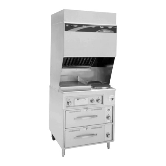
WV-2HGRW
OWNERS MANUAL
WV2HG SERIES
GRIDDLE / HOTPLATE
COOKTOP
with
UNIVERSAL HOOD
MODELS:
WV2HFG
WV2HFGRW
WV2HFGRWT
WV2HSG
WV2HSGRW
WV2HSGRWT
Includes
INSTALLATION
USE & CARE
EXPLODED VIEW
PARTS LIST
WIRING DIAGRAM
M508
508
13
0125
Advertisement
Table of Contents

Related Manuals for Wells WV2HFG


Summary of Contents for Wells WV2HFG
- Page 1 Additional manuals are available from your WELLS DEALER. THIS MANUAL MUST BE READ AND UNDERSTOOD BY ALL PERSONS USING OR INSTALLING THIS APPLIANCE. Contact your WELLS DEALER if you have any questions concerning installation, operation or maintenance of this equipment.
-
Page 2: Warranty
LIMITED WARRANTY STATEMENT Unless otherwise specified, all commercial cooking The prices charged by Wells Bloomfield for its products equipment manufactured by WELLS BLOOMFIELD, LLC is are based upon the limitations in this warranty. Seller’s warranted against defects in materials and workmanship... -
Page 3: Table Of Contents
CUSTOMER SERVICE DATA ..... . . 41 INTRODUCTION Thank You for purchasing this Wells Bloomfield appliance. Proper installation, professional operation and consistent maintenance of this appliance will ensure that it gives you the very best performance and a long, economical service life. -
Page 4: Features & Operating Controls
FEATURES & OPERATING CONTROLS IL2602 Fig. 1 Ventilator Section Operating Features & Controls... - Page 5 FEATURES & OPERATING CONTROLS (continued) VENTILATOR SECTION ITEM DESCRIPTION COMMENT Gives manufacturer, make and model description. Also lists voltage and amperage NAMEPLATE data. APPLIANCE LIGHT ON when hood power switch is ON. Illuminates cooktop. FIRE SUPPRESSION AGENT Container for Ansulex™ Low-pH liquid fire suppression liquid. TANK (1.5 gal.) ADJUSTABLE (FRONT) LEG Allows the unit to be leveled.
- Page 6 FEATURES & OPERATING CONTROLS (continued) VENTILATOR REPLACE REPLACE SERVICE CHECK FILTERS REQUIRED POWER ON PREFILTER FILTER PACK IL2603 Fig. 2 Ventilator Section Controls & Indicator Lights GRIDDLE SECTION COOKTOP CONTROLS HOTPLATE SECTION OPTIONAL DRAWER WARMER SECTION IL2604 Fig. 3 Griddle, Hotplate and Drawer Warmer Sections...
- Page 7 FEATURES & OPERATING CONTROLS (continued) FEATURES & OPERATING CONTROLS (continued) ITEM DESCRIPTION COMMENT VENTILATOR SECTION CONTROLS Energizes blower motor. If, after 10 seconds, proper conditions are met, cooking appliances are energized. V.01 POWER SWITCH Appliance light is ON when POWER SWITCH is ON. V.02 POWER ON INDICATOR GREEN.
-
Page 8: Precautions & General Information
PRECAUTIONS AND GENERAL INFORMATION NOTE: Fire suppression system and all associated components DANGER must only be serviced by an authorized Ansul® Distributor. All setup, FIRE charging, repair and/or adjustment of the fire suppression system must HAZARD be performed by an Authorized Ansul® Distributor ONLY. IMPORTANT: If a remote pull station is installed, both rear casters (9) must be replaced with legs to deter moving the unit. - Page 9 CAUTION: Hot Surface Use only genuine Wells replacement parts and filters, call (314) 678-6314 or your authorized Wells service agent. Parts supplied by others will void your warranty and may not provide safe Exposed surfaces can be hot operation.
-
Page 10: Agency Listing Information
(i.e. red SERVICE REQUIRED light is on), when the user fails to have the proper replacement pre-filter and/or filter pack on hand. The Ventless Cooking System™ hood is designed as part of a WELLS cooking appliance only. No other use of this product is authorized by the manufacturer or its agents. -
Page 11: Installation
INSTALLATION NOTE: DO NOT discard UNPACKING & INSPECTION the carton or other packing Carefully remove the appliance from the carton. Remove all protective materials until you have plastic film, packing materials and accessories from the Appliance inspected the appliance for before connecting electrical power or otherwise performing any hidden damage and tested it installation procedure. - Page 12 INSTALLATION (continued) IMPORTANT! SERVICE TECHNICIAN INSTALLATION NOTES Verify that this VENTILATOR An Ansul® technician must charge and arm the fire suppression system and food cooking equipment before the ventilator blower will operate. See page 11. installation is in compliance with the specifications listed Installation and start up must be performed by an Authorized Installation Company.
- Page 13 (i.e. remove rear casters and replace with legs). Additional legs may be ordered through an Authorized Wells Service Agency. See page 29. 2. The FIRE SUPPRESSION SYSTEM is comprised of a pressurized cartridge &...
- Page 14 FILTER HOOK over the lip of the top filter rail. Then lower and seat the assembly into the top indentation of Use only genuine Wells the lower filter rail. replacement parts and filters,...
- Page 15 INSTALLATION (continued) GREASE DRIP TRAY INSTALLATION CAUTION: Install the GREASE DRIP TRAY on the hanger brackets, directly Burn Hazard below the grease baffle. DO NOT OPERATE UNLESS ROLL WARMER DRAWER INSTALLATION THE GREASE DRIP TRAY IS INSTALLED. Be sure roller catches (inside warmer cavity) are in the open position. Install drawer assemblies in drawer slides.
-
Page 16: Operation
OPERATION VENTILATOR OPERATION CAUTION: Press the VENTILATOR POWER switch to ON. The green Hot Surface VENTILATOR POWER light will glow and the blower fan will start. After a short time, if all filters are sensed as being in position and not Exposed surfaces can be hot clogged, the cooking appliance will be energized. - Page 17 PREPARING THE GRIDDLE SURFACE 1. SEASONING STANDARD GRIDDLES Exposed surfaces can be hot As manufactured, the steel surface of your Wells griddle has to the touch and may cause microscopic pores. It is important to fill these pores with oil in order burns.
- Page 18 Moist heat with pans: and method of operation will This Wells warmer is designed to accommodate any combination enable you to determine the of standard-size, steam table pans. temperature control and air Place a small amount of water in drawer pan.
- Page 19 OPERATION (continued) DRAWER WARMER OPERATION (when provided) ITEM DESCRIPTION PROCESS Key: Press to view actual temperature of cavity. 4 Character LED Display: Normally shows SETPOINT temperature. ºF or ºC Indicator: Glows to indicate if unit is configured for degrees Fahrenheit or degrees Celsius. LOAD Indicator: Glows when heating element is energized.
-
Page 20: Cleaning Instructions
CLEANING INSTRUCTIONS VENTILATOR SECTION CLEANING INSTRUCTIONS CAUTION: Electric Shock Hazard PREPARATION Disconnect appliance from electric power Disconnect appliance Allow to cool before cleaning from electric power before cleaning. FREQUENCY Weekly TOOLS CAUTION: Hot Surface Warm water and a mild detergent Soft clean cloth or sponge Exposed surfaces can be hot Bristle brush... - Page 21 CLEANING INSTRUCTIONS (continued) HOTPLATE SECTION CAUTION: Electric Shock PREPARATION Hazard Disconnect appliance from electric power Disconnect appliance Allow to cool before cleaning from electric power before cleaning. FREQUENCY Daily TOOLS CAUTION: Warm water and a mild detergent Hot Surface Soft clean cloth or sponge Exposed surfaces can be hot Plastic scouring pad, plastic scraper to the touch and may cause...
- Page 22 CLEANING INSTRUCTIONS (continued) GRIDDLE CLEANING INSTRUCTIONS CAUTION: Hot Surface PRECAUTIONS Griddle surfaces are HOT. Wear appropriate heat protective gloves, apron and goggles Exposed surfaces can be hot FREQUENCY As Noted to the touch and may cause Scraper, Pumice Stone or Griddle Brick burns.
- Page 23 CLEANING INSTRUCTIONS (continued) DRAWER WARMER CLEANING INSTRUCTIONS CAUTION: Electric Shock Turn control knob to OFF. PRECAUTIONS: Hazard Allow drawers to cool before proceeding. Remove drawer pans and Humitrol racks. Disconnect appliance from electric power before cleaning. FREQUENCY: Minimum -Daily TOOLS: Warm water and mild detergent CAUTION: Hot Surface...
-
Page 24: Maintenance Instructions
MAINTENANCE INSTRUCTIONS ADJUSTMENTS AND LUBRICATION CAUTION: Turn control knob to OFF. Unplug warmer Shock Hazard PRECAUTIONS: Allow drawers to cool before proceeding. Disconnect appliance from Remove drawer pans and Humitrol racks electric power before cleaning. FREQUENCY: Minimum - monthly. Every 2 weeks recommended. Screwdrivers, Phillips (+) and flat blade (-). -
Page 25: Troubleshooting Suggestions
Cooking appliances not energized Ansul® system discharged or not cocked. Contact Ansul® Distributor for service. (Buzzer sounds) Internal damage Contact Authorized Wells Service Agent for repairs. Set Hotplate Temperature Control to desired Hotplate Temperature Control not set temperature. Each hotplate is controlled individually. -
Page 26: Maintenance Schedules
MAINTENANCE SCHEDULES USE AND MAINTENANCE 6-MONTH MAINTENANCE (MUST BE PERFORMED BY AN SHALL BE IN ACCORDANCE AUTHORIZED ANSUL® DISTRIBUTOR ONLY): WITH THE STANDARD FOR VENTILATION CONTROL Inspect and test total operation including FIRE DAMPER and AND FIRE PROTECTION OF all SAFETY INTERLOCKS. COMMERCIAL COOKING All FIRE SUPPRESSION SYSTEM actuation components OPERATIONS, N.F.P.A 17A &... -
Page 29: Msds (Ansulex Low Ph)
ANSUL A N S U L IN C O R P O R AT E D MATERIAL SAFETY DATA SHEET ® M A R IN E T T E , W I 5 4 14 3-2 54 2 ANSULEX Low pH Q U IC K ID E N TIFIE R (In P la n t C o m m o n N a m e ) E m erg e nc y M a n u fac tu re r’s... - Page 30 SECTION 5 - HEALTH HAZARDS ANSULEX Low pH (continued) Th res h o ld N o ne E s tab lish ed L im it Va lu e : R o u te s o f E n try: Irritan t E ye C o n tac t: S kin C o n ta c t: Irritan t...
-
Page 31: Ansul® Components
ANSUL® FIRE SUPPRESSION SYSTEM COMPONENTS FOR USE ONLY BY AUTHORIZED ANSUL© SERVICE PERSONNEL Refer to Ansul© part no. 418078-05 ref. NOZZLE 290 R-102 Restaurant Fire Suppression ANSUL© p/n 419342 System Design, Installation, Recharge and Maintenance ref. ADAPTER, QUICK-SEAL 3/8” ANSUL© p/n 77284 FUSIBLE LINK ref. -
Page 32: Exploded View & Parts List
EXPLODED VIEW & PARTS LIST HOOD SECTION - CABINET COMPONENTS INTERNAL BRACKETS Sold by the Foot -RW UNITS CABINET DOORS (NON -RW UNITS) WV2HG; Hood Section - Cabinet Comonents IL2278a, PL508... - Page 33 EXPLODED VIEW & PARTS LIST HOOD SECTION - CABINET COMPONENTS Model: WV2HG Hood Section - Cabinet Components Fig No Part No Description Application 2E-305098 LIGHT HOUSING, VCS HOOD 2S-305100 LIGHT BULB/100W-230V, FROSTED 2Q-305099 GLASS GLOBE VCS HOOD M3-304405 TRAY GREASE DRIP HOOD 2O-308131 REMOTE PULL STATION, RED 5E-20804...
- Page 34 EXPLODED VIEW & PARTS LIST HOOD SECTION - ELECTRICAL & VACUUM COMPONENTS PORT A PORT C PORT B PORT A PORT C PORT C PORT B (3 pl) ELECTRICAL - REAR OF LOWER CABINET ELECTRICAL - UNDER HOOD WV2HG; Hood Section - Electrical & Vaccum Comonents IL2279a...
- Page 35 EXPLODED VIEW & PARTS LIST HOOD SECTION - ELECTRICAL & VACUUM COMPONENTS Model: WV2HG Hood Section - Electrical Components Fig No Part No Description Application 2U-302584 BLOWER ASSY UNIVERSAL 2E-302593 SWITCH VACCUM #4 2E-302591 SWITCH VACCUM #2 2E-302590 SWITCH VACCUM #1 2E-302592 SWITCH VACCUM #3 2K-37748...
- Page 36 EXPLODED VIEW & PARTS LIST COOKTOP SECTION - CABINET & ELECTRICAL COMPONENTS IL2280, PL508 WV2HG; Cooktop Section - Cabinet & Electrical Comonents...
- Page 37 EXPLODED VIEW & PARTS LIST COOKTOP SECTION - CABINET & ELECTRICAL COMPONENTS Model: WV2HG Cooktop Section - Cabinet & Electrical Components Fig No Part No Description Application 2N-30512UL ELEMENT 240V 3000W G7-32038 CLAMP ELEMENT END LRG GRIDDLE G7-31968 CLAMP ELEMENT CTR SMALL GRIDDLE WS-57407 8SF INSULATION OVERSIZED G7-33474...
- Page 38 EXPLODED VIEW & PARTS LIST DRAWER WARMER SECTION - CABINET & ELECTRICAL COMPONENTS part of # 18 WS-67096 heavy duty drawer assy complete WS-65923 (set - includes left and right) WV2HG; Drawer Warmer Section - Cabinet & Electrical Comonents IL2281a...
- Page 39 EXPLODED VIEW & PARTS LIST DRAWER WARMER SECTION - CABINET & ELECTRICAL COMPONENTS Model: WV2HG Drawer Warmer Section - Cabinet & Electrical Components Fig No Part No Description Application WS-20624 RACK HUMITROL RWS OPTIONAL C8-46840 PAN DRAWER RW/RWHD WS-67096 DRAWER ASY KIT RWHD C8-49251 SLIDE VENT ASSY RWN 2C-35530...
-
Page 40: Wiring Diagram
WIRING DIAGRAM HOOD SECTION from p/n 2M-305991 Rev. A... - Page 41 WIRING DIAGRAM COOKTOP SECTION from p/n 2M-305991 Rev. A...
- Page 42 WIRING DIAGRAM DRAWER WARMER SECTION RW-STYLE DRAWER WARMER SECTION - RWT-STYLE WIRING DIAGRAM RWT-26 from p/n 307532 Rev -...
-
Page 43: Parts & Service
DD-22412 Service Dept. WELLS BULLETIN (ANSUL® PARTS LIST) DD-303331 phone: (314) 678-6314 NOTE: Ansul® Manual 418087-05 and Wells Bulletin 303331 are fax: (314) 781-2714 intended for use by authorized Ansul® service personnel only. Ansul® Manual 418087-05 must be obtained through Service Parts Department your authorized Ansul®... - Page 44 WELLS BLOOMFIELD, LLC 10 Sunnen Dr., St. Louis, MO 63143 telephone: 314-678-6314 fax: 314-781-2714 www.wellsbloomfield.com...
Need help?
Do you have a question about the WV2HFG and is the answer not in the manual?
Questions and answers