Advertisement
Quick Links
Feature ................................................................................................................ 2
Function .............................................................................................................. 2
Specification ....................................................................................................... 2
Display ................................................................................................................. 2
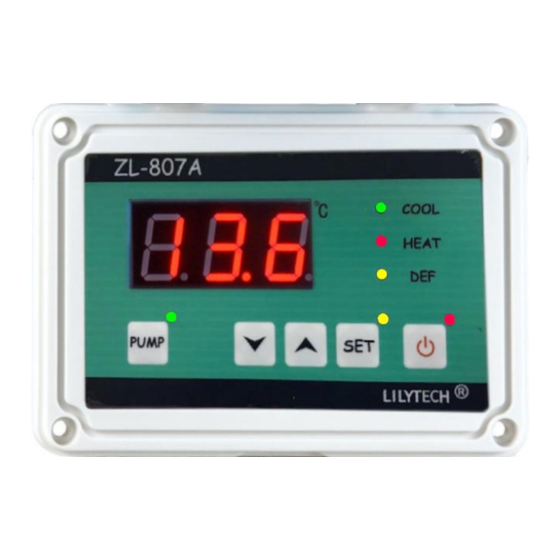
Panel ................................................................................................................................................................ 2
Display indication ....................................................................................................................................... 2
Alarming code .............................................................................................................................................. 3
Operation ............................................................................................................ 3
Set setpoint ................................................................................................................................................... 3
Set parameter ............................................................................................................................................... 3
Check pipe temperature .......................................................................................................................... 3
Parameter code table ................................................................................................................................ 3
Control ................................................................................................................. 3
On/Offline control ....................................................................................................................................... 3
Cooling only mode (F01 = 1) .................................................................................................................. 3
Constant temperature mode (F01 = 0) ............................................................................................... 4
Heat by compressor (F02 = 0) ........................................................................................... 4
Heat by electrical heater (F02 = 1) .................................................................................... 4
Defrost (F02 = 0, and under heating mode) ...................................................................... 4
Forced defrost (F02 = 0, under heating mode) .................................................................. 4
Fast launch (Force the compressor energized) ............................................................................ 4
Pump control ................................................................................................................................................ 4
External alarm input .................................................................................................................................. 4
Delay protection for compressor ........................................................................................................ 4
Auto restart ................................................................................................................................................... 4
Calibration ..................................................................................................................................................... 4
Waring for sensor failure ........................................................................................................................ 4
Restore to factory settings ..................................................................................................................... 5
Wiring diagram ................................................................................................... 5
Diagram one: heating by compressor ............................................................................................... 5
Diagram two: heating by heater ........................................................................................................... 5
Dimension ........................................................................................................... 6
Out size ........................................................................................................................................................... 6
Embedded hole ........................................................................................................................................... 6
If the cable protection rubbers could be removed during installation ................................ 6
If the cable protection rubbers could not be removed during installation .......................... 6
ZL-807A Controller
Instruction Manual
V1.0b
Catalog
Page 1, Total 6 Pages
Suzhou Lily Tech. Co., Ltd.
Advertisement

Subscribe to Our Youtube Channel
Related Manuals for Lilytech ZL-807A


Summary of Contents for Lilytech ZL-807A
- Page 1 Suzhou Lily Tech. Co., Ltd. ZL-807A Controller Instruction Manual V1.0b Catalog Feature ........................ 2 Function ......................2 Specification ....................... 2 Display ......................... 2 Panel ................................2 Display indication ............................2 Alarming code .............................. 3 Operation ......................3 Set setpoint ..............................3 Set parameter ...............................
-
Page 2: Specification
V1.0b Feature ZL-807A is water temperature controller. It could work in cooling mode, or constant temperature control mode. It can drive 2 HP compressor directly. And it has water pump on/off control function. With IP60 panel, friendly to operate, easy to install. It could control sea food chiller, aquarium pool, or water tank’s temperature. - Page 3 Suzhou Lily Tech. Co., Ltd. Alarming code Code Remark Water sensor failure Defrost sensor failure External alarming (all controller outputs will be de-energized) Operation Set setpoint Enter into temperature setting status: Keep【SET】depressed for 3 seconds. The SET lamp will be on. The current setpoint displays. Press【▲】or【▼】to set setpoint.
- Page 4 Suzhou Lily Tech. Co., Ltd. Constant temperature mode (F01 = 0) Heat by compressor (F02 = 0) If (water temperature) ≥ (setpoint + F03), and the compressor has stopped for F06, the compressor starts cooling. If (water temperature) ≤ (setpoint), the compressor de-energized. If (water temperature) ≤...
- Page 5 Suzhou Lily Tech. Co., Ltd. Restore to factory settings Keep【SET】and【▲】depressed simultaneously for 2 seconds, display “UnL”. Press【▼】twice, all settings will restore to factory default values. Wiring diagram Diagram one: heating by compressor Diagram two: heating by heater Page 5, Total 6 Pages...
- Page 6 Suzhou Lily Tech. Co., Ltd. Dimension Case size Embedded hole If the cable protection rubbers could be If the cable protection rubbers could not be removed during installation removed during installation Hole size = 136.1 * 86.5 mm, R = 7 mm Hole size: 135.1 * 90.5 mm, R = 6 mm Page 6, Total 6 Pages...
Need help?
Do you have a question about the ZL-807A and is the answer not in the manual?
Questions and answers