Advertisement
Quick Links
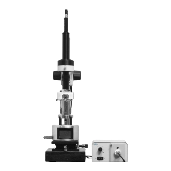
NanoScope Optical Viewing System
Support Note 213 details the components, assembly, and adjustments to the NanoScope
Optical Viewing System, model OMV-Universal. Compliance with the following assembly
and adjustment directions are essential to successful and safe installation. This support
note includes:
•
•
•
•
Rev.
C
B
© Bruker Corporation, 2008, 2011
112 Robin Hill Road
Santa Barbara, CA 93117
805.967.1400
Model OMV-UNIVERSAL
Components:
Section 213.1
Assembly of Optical Viewing System:
•
Remove Contents from Packing Box:
•
Screw Support Pole to Granite Base:
•
Mount Split Collar and Delrin Washer:
•
Install Focus Mount Assembly:
•
Mount the Optical Assembly:
•
Attach Camera and Fiber Optic Cable:
•
Connect the Illuminator:
•
Connect the Video Output:
Adjustment of the Optical Viewing System:
•
Mount the SPM and Adjust the Camera Height:
•
Set Illuminator Level:
•
Fine Alignment of SPM and Camera:
Suggestions:
Section 213.4
Document Revision History: Support Note 213
Date
Sections
01-19-2011
Re-branded
11/21/08
OMV-Universal Update
Support Note 213, Revision C
Section 213.2
Section 311.2.1
Section 311.2.2
Section 311.2.3
Section 311.2.4
Section 311.2.5
Section 311.2.6
Section 311.2.7
Section 311.2.8
Section 213.3
Section 311.3.2
Section 311.3.3
Ref. DCR
N/A
Section 311.3.1
Approval
Ruth Wishengrad
D. Paszkeicz
Part Number: 013-213-000
Advertisement

Related Manuals for Bruker NanoScope OMV-UNIVERSAL


Summary of Contents for Bruker NanoScope OMV-UNIVERSAL
- Page 1 Section 213.4 Document Revision History: Support Note 213 Rev. Date Sections Ref. DCR Approval 01-19-2011 Re-branded Ruth Wishengrad 11/21/08 OMV-Universal Update D. Paszkeicz © Bruker Corporation, 2008, 2011 Part Number: 013-213-000 112 Robin Hill Road Santa Barbara, CA 93117 805.967.1400...
- Page 2 Bruker offers the NanoScope optical viewing system as an aid for aligning “TipView” STM and MultiMode™ scanning probe microscopes (SPMs). The optical viewing system consists of a camera, which is mounted vertically over the head of the SPM to view both sample surface and tip.
- Page 3 Components 213.1 Components The optical viewing system includes the following: • Granite Base— The twenty pound granite slab is supported on four isolation pads to dampen vibration for general scanning. An X-Y translation stage is bolted to the granite for convenient lateral positioning of the SPM. For extremely high magnification scans, the optical viewing system should be set atop a vibration isolation table.
- Page 4 311.2.1 Remove Contents from Packing Box Carefully unpack all components from the packing box and check against the list supplied in this document. If components are damaged or missing, contact Bruker immediately. 311.2.2 Screw Support Pole to Granite Base Set the granite base on its side, with the counter-bored side of the hole accessible, and both X-Y translation stage adjustment knobs projecting into free space.
- Page 5 Assembly of Optical Viewing System 311.2.3 Mount Split Collar and Delrin Washer Orient the split collar with its grooved side upward, then slide it over the support pole and position half way down the pole. Tighten the split collar until the collar is firmly secured. Slide the delrin washer over the pole and rest atop the split collar.
- Page 6 Assembly of Optical Viewing System 311.2.6 Attach Camera and Fiber Optic Cable Attach the camera cable to the top of the camera using the elbow connector provided. The connector is keyed so that it plugs onto the camera’s connector in the proper orientation. Push the connector down until the outside ring snaps into place, locking the cable connector to the camera.
- Page 7 Assembly of Optical Viewing System 311.2.7 Connect the Illuminator The free end of the fiber optic cable mounts in the front of the illuminator. The included adaptor, an aluminum ring, reduces the nosepiece of the illuminator down to hold the 5-mm diameter fiber cable.
- Page 8 Adjustment of the Optical Viewing System 213.3 Adjustment of the Optical Viewing System 311.3.1 Mount the SPM and Adjust the Camera Height Using the focus mount assembly’s adjustment knob, raise the optical viewing system to a height sufficient to clear the SPM to be used with the optical viewing system. Set the SPM atop the X-Y translation stage on the granite base.
- Page 9 Suggestions 213.4 Suggestions When operating your SPM with the optical viewing system, it is recommended that the tip be brought close to the sample surface BEFORE aligning the laser with the tip. If specks of dirt appear on the video image, clean the camera objective’s dust cover (the clear glass plate located on the business end of the camera).
Need help?
Do you have a question about the NanoScope OMV-UNIVERSAL and is the answer not in the manual?
Questions and answers