Table of Contents
Advertisement
Available languages
Available languages
Quick Links
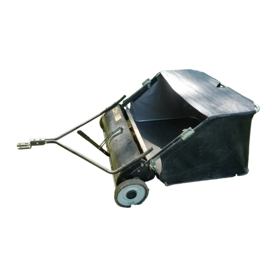
OWNERS MANUAL
MANUAL DEL USUARIO
NOTICE D'UTILISATION
Model No.
Modelo No.
Modèle No.
45-0331
CAUTION:
Read Rules for
Safe Operation
and Instructions
PRECAUCION:
Lea cuidadosamente
los Procedimientos e
Instrucciones para la
Operación Segura de la
ATTENTION:
Lire et suivre attentivement
les instructions et
consignes de sécurité de
cette notice.
PRINTED IN U.S.A.
™
BARREDORA DE CESPED DE 96 cm
Carefully
•
•
•
•
•
Máquina.
the fastest way to purchase parts www.speedepart.com
38" LAWNSWEEPER
BALAYEUSE DE 96 cm
Safety
Assembly
Operation
Maintenance
Parts
•
Seguridad
•
Montaje
•
Operación
•
Mantenimiento
•
Piezas de Repuesto
•
Sécurité
•
Assemblage
•
Fonctionnement
•
Maintenance
•
Pièces de Rechange
FORM NO. 49131 (REV. 4/05)
Advertisement
Table of Contents

Related Manuals for Agri-Fab 45-0331


Summary of Contents for Agri-Fab 45-0331
- Page 1 ™ OWNERS MANUAL MANUAL DEL USUARIO NOTICE D’UTILISATION Model No. Modelo No. Modèle No. 45-0331 CAUTION: Read Rules for Safe Operation and Instructions Carefully PRECAUCION: Lea cuidadosamente los Procedimientos e Instrucciones para la Operación Segura de la Máquina. ATTENTION: Lire et suivre attentivement les instructions et consignes de sécurité...
- Page 2 CARTON CONTENTS (Loose Parts in Carton) CONTENIDO DE LA CAJA (Partes Sueltas en la Caja) CONTENU DU CARTON (Pièces en Vrac Dans le Carton) ENGLISH 1. Sweeper Housing Assembly 2. Bag Arm Tube (2) 3. Hitch Tube, L.H. 4. Hitch Bracket 5.
- Page 3 REF. QTY. DESCRIPTION Hex Bolt, 5/16 x 2-1/2" Lg. Hex Bolt, 5/16 x 2" Lg. Curved Head Bolt, 5/16" x 1-5/8" Carriage Bolt, 5/16" x 1-1/2" Carriage Bolt, 5/16 x 3/4" Lg. Hex Bolt, 5/16" x 3/4" Hex Lock Nut, 5/16" Hex Nut (Plain), 5/16"...
-
Page 4: Safety Rules
Remember, any power equipment can cause injury if operated improperly or if the user does not understand how to operate the equipment. Exercise caution at all times when using power equipment. 1. Read the vehicle and sweeper owners manuals and know how to operate your vehicle and sweeper before using this sweeper attachment. -
Page 5: Table Of Contents
CONTENTS SAFETY ... 4 ASSEMBLY ... 5 OPERATION ... 11 MAINTENANCE ... 11 STORAGE ... 11 SERVICE AND ADJUSTMENTS ... 12 TROUBLESHOOTING ... 12 REPAIR PARTS ... 22 ASSEMBLY TOOLS REQUIRED FOR ASSEMBLY Knife or Scissors 1/2" Open End or Box End Wrenches All loose parts are shown on page 2. - Page 6 If your tractor hitch has 11" to 13" ground clearance re- fer to fi gure 4. If your tractor hitch has 8" to 11" ground clearance refer to fi gure 5. 5. (Figure 4 or 5) Assemble the hitch brackets to the hitch tubes using two 5/16"...
-
Page 7: Assembly
11. (Figure 8) Position the height adjustment handle side to side so that the tooth lock washer (M) can fi t between the handle and the height adjustment strap. Tighten the nuts securing the height adjustment handle. 12. (Figure 8) Insert the 5/16" x 3/4" carriage bolt (E) through the height adjustment handle. - Page 8 5. (Figure 12) Place the assembled lower hopper tubes into the bottom of the hopper bag. 6. (Figure 12) Attach the ends of the lower hopper side tubes to the inside of the upper hopper side tubes using two 3/8" x 1/2" clevis pins (P) inserted from the inside, and two 3/32"...
- Page 9 11. (Figure 16) Feel along the stitched fl ap on the hopper bag to locate the lower hole in each upper hopper side tube. Pierce a hole through both sides of the stitched fl aps in alignment with the lower hole. UPPER HOLE LOWER HOLE UPPER HOPPER SIDE TUBE...
- Page 10 ATTACHING SWEEPER HITCH TO TRACTOR (Figures 20, 21, 22) 1. Place the tractor and sweeper on a fl at level surface. 2. Set the sweeper height adjustment handle to about the middle of its adjustment range. 3. Attach the sweeper hitch brackets to the tractor hitch, arranging the 3/4"...
-
Page 11: Operation
OPERATION HOW TO USE YOUR SWEEPER BRUSH HEIGHT ADJUSTMENT To adjust your sweeper brushes to the best operating height, loosen the adjustment knob and push down on the height adjustment lever to raise the brush. Best ad- justment is when the brush setting is 1/2" down into the grass. -
Page 12: Service And Adjustments
SERVICE AND ADJUSTMENTS BRUSH REPLACEMENT NOTE: Brush replacement should be done one brush at a time. 1. Remove the hopper bag from the sweeper. 2. (Figure 25) Loosen the hex bolts and lock nuts on two single brush retainers which clamp one brush to the double brush retainers. -
Page 14: Normas De Seguridad
Recuerde, cualquier equipo motorizado puede causar lesiones si se usa en forma inapropiada o si el usuario no entiende como operarlo. Sea precavido siempre que use equipo motorizado. 1. Lea los manuales del usuario de la barredora y del vehículo de arrastre y conozca su operación antes de usar este accesorio de barredora. - Page 15 INDICE SEGURIDAD ... 14 INSTRUCCIONES DE ARMADO ... 15 OPERACION ... 16 MANTENIMIENTO ... 16 ALMACENAMIENTO ... 17 SERVICIO Y AJUSTES ... 17 RESOLUCION DE PROBLEMAS ... 17 REPUESTOS ... 22 ARMADO HERRAMIENTAS REQUERIDAS PARA EL ARMADO (1) Cuchilla o tijeras (2) Llaves de Boca Abierta o de Estrella de 1/2”...
-
Page 16: Mantenimiento
13. (Figura 17) Coloque una tapa de vinilo (V) en el extremo de cada tubo del brazo de la bolsa. 14. (Figura 18) Asegure la cuerda a la parte superior del centro superior del marco de la bolsa de la tolva. 15. -
Page 17: Servicio Y Ajustes
ALMACENAMIENTO PRECAUCION: Antes de almacenar la barre- dora, desocupe siempre la bolsa de la tolva para evitar que ocurra una combustión espontánea. Limpie completamente la barredora y la bolsa de la tolva para ayudar a prevenir la oxidación y el moho. Para doblar la bolsa de la tolva cuando se va a guardar, retire las dos barras de soporte de la tolva de la parte trasera de la misma. - Page 18 Tout appareil mécanique utilisé incorrectement peut être la cause de blessures. L’utilisateur doit bien en maîtriser le fonc- tionnement. Observez en tout temps la plus grande prudence lorsque vous utilisez un appareil mécanique. 1. Lisez les manuels du propriétaire du véhicule et de la balayeuse et apprenez à...
-
Page 19: Montage
TABLE DES MATIÈRES SÉCURITÉ ... 18 MONTAGE ... 19 FONCTIONNEMENT ... 20 MAINTENANCE ... 20 ENTREPOSAGE ... 21 ENTRETIEN ET RÉGLAGES ... 21 DÉPANNAGE ... 21 PIÈCES DE RECHANGE ... 22 MONTAGE OUTILS NÉCÉSSAIRES AU MONTAGE (1) Couteau ou paire de ciseaux (2) Clés polygonale ou à... - Page 20 12. (Figure 17) Insérez une goupille (S) dans le trou inférieur de chaque tube latéral supérieur de la trémie. Assemblez ensuite le tube du bras du sac avec chaque goupille en le fi xant avec une goupille fendue (O). 13. (Figure 17) Insérez un bouchon en vinyle (V) à l’extrémité de chaque tube du bras du sac.
-
Page 21: Entretien Et Réglages
ENTREPOSAGE ATTENTION Avant d’entreposer la balayeuse, videz toujours le sac de récupération des débris afi n d’éviter une combustion spontanée. Nettoyez la balayeuse et la trémie parfaitement afi n de prévenir la rouille et la moisissure. Pour plier le sac de récupération des débris en vue de son entreposage, démontez les deux tiges de support situées à... - Page 22 REPAIR PARTS FOR MODEL 45-0331 38" LAWNSWEEPER...
- Page 23 REPAIR PARTS FOR MODEL 45-0331 38" LAWNSWEEPER Ref. Part Qty. Description 48618 Hitch Tube, R.H. 48619 Hitch Tube, L.H. 24950 End Plate, R.H. 24951 End Plate, L.H. 24971 Wrapper 43175 Bolt, Hex 1/4-20 x 1/2" Lg. C-9M5732 14 Rivet, Pop...
-
Page 24: Repair Parts
REPAIR PARTS Agri-Fab, Inc. 303 West Raymond Sullivan, IL. 61951 217-728-8388 www.agri-fab.com...
Need help?
Do you have a question about the 45-0331 and is the answer not in the manual?
Questions and answers