Table of Contents
Advertisement
Available languages
Available languages
OWNERS mANUAL
mANUAL DEL USUARIO
NOTICE D'UTILISATION
model No.
modelo No.
modèle No.
45-03201
45-03201-062
CAUTION:
Read Rules for
Safe Operation
and Instructions
PRECAUCION:
Lea cuidadosamente
los Procedimientos e
Instrucciones para la
Operación Segura de la
ATTENTION:
Lire et suivre attentivement
les instructions et
consignes de sécurité de
cette notice.
PRINTED IN U.S.A.
™
BARREDORA DE CESPED DE 106 cm
• Safety
• Assembly
Carefully
• Operation
• Maintenance
• Parts
Máquina.
the fastest way to purchase parts www.speedepart.com
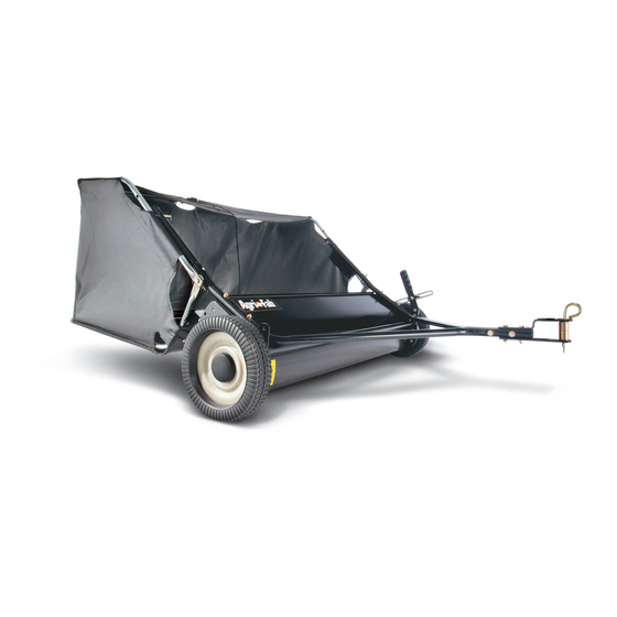
42" LAWNSWEEPER
BALAYEUSE DE PELOUSE 106 cm
• Seguridad
• Montaje
• Operación
• Mantenimiento
• Piezas de Repuesto
• Sécurité
• Assemblage
• Fonctionnement
• Maintenance
• Pièces de Rechange
FORM NO. 40636 (REV. 3/11/08)
Advertisement
Table of Contents

Related Manuals for Agri-Fab 45-03201-062


Summary of Contents for Agri-Fab 45-03201-062
- Page 1 ™ OWNERS mANUAL mANUAL DEL USUARIO NOTICE D’UTILISATION model No. modelo No. modèle No. 45-03201 45-03201-062 CAUTION: Read Rules for Safe Operation and Instructions Carefully PRECAUCION: Lea cuidadosamente los Procedimientos e Instrucciones para la Operación Segura de la Máquina. ATTENTION:...
- Page 2 CARTON CONTENTS (Loose Parts in Carton) CONTENIDO DE LA CAJA (Partes Sueltas en la Caja) CONTENU DU CARTON (Pièces en Vrac Dans le Carton) ENGLISH 1. Sweeper Housing Assembly 2. Bag Arm Tube (2) 3. Hitch Tube, L.H. 4. Hitch Bracket 5. Hitch Bracket (Straight) 6. Height Adjustment Strap 7. Height Adjustment Handle 8. Hitch Tube, R.H. 9. Brush Assembly (2) 10. Upper Hopper Side Tube (2) 11. Rear Hopper Tube (2) 12. Lower Hopper Side Tube (2) 13.
- Page 3 DESCRIPTION Hex Bolt, 5/16 x 2-1/2" Lg. Hex Bolt, 5/16 x 2" Lg. Carriage Bolt, 5/16" x 1-1/2" Hex Bolt, 5/16 x 1-1/4" Lg. Hex Bolt, 5/16" x 1" Carriage Bolt, 5/16" x 1" Hex Bolt, 1/4" x 1" Nylock Nut, 1/4" Nylock Nut, 5/16" Flat Washer, 5/16" Star Washer Hair Cotter Pin, 1/8" Hair Cotter Pin, 3/32" ENGLISH SHOWN FULL SIZE NOT SHOWN FULL SIZE DESCRIPTION Clevis Pin, 3/8" x 1/2" Clevis Pin, 1/4" x 1-1/8" Clevis Pin, 1/4" x 1-3/4" Clevis Pin, 3/8" x 3" Pivot Bushing Spacer Bushing Hitch Spacer, 3/4" Vinyl Cap Grip Knob, Plastic Hitch Pin Plastic Plug...
-
Page 4: Safety Rules
Remember, any power equipment can cause injury if operated improperly or if the user does not understand how to operate the equipment. Exercise caution at all times when using power equipment. 1. Read the vehicle and sweeper owners manuals and know how to operate your vehicle and sweeper before using this sweeper attachment. Always instruct other users before they operate the sweeper. 2. Do not permit children to operate sweeper. 3. Do not permit anyone to ride on sweeper. 4. Never attach the hopper rope to any part of your body or clothing! Never hold onto the rope while towing the sweeper! Attach the rope to the towing vehicle to keep it away from wheels and rotating parts. 5. Operate the sweeper at reduced speed on rough terrain, near ditches and on hillsides to prevent loss of control. -
Page 5: Tools Required For Assembly
ASSEmBLY TOOLS REqUIRED FOR ASSEmBLY (2) 7/16" Open End or Box End Wrenches (2) 1/2" Open End or Box End Wrenches All loose parts are shown on page 2. Fasteners in the parts bag are shown full size on page 3. Remove the hardware pack and all loose parts from the carton and verify that all the parts and fasteners shown on pages 2 and 3 are included. ASSEmBLY OF SWEEPER Note: Right hand (R.H.) and left hand (L.H.) are determined from the operator's position while seated on the tractor. 1. (Figure 1) Each brush assembly has one brush retainer marked with either red or black ink. Lay out the brush assemblies as shown so that the brush retainers marked with ink are in the middle with the red one on the right and the black one on the left. - Page 6 3. (Figure 3) Attach the brush assembly with the black brush retainer to the left end of the brush shaft using two 1/4" x 1" hex bolts (G) and 1/4" nylock nuts (I). The brush retainer marked with black ink must be placed to the middle of the sweeper. 4. (Figure 3) Turn a wheel to rotate the brushes. (The wheels drive the brushes in one direction only.) The overlap bristles should be on the back side of the brush as it rotates. 1/4" x 1" HEX BOLT (G) BRUSH RETAINER MARKED BLACK ENGLISH...
- Page 7 If your tractor hitch has 10" to 13" ground clearance refer to figure 6. If your tractor hitch has 8" to 10" ground clearance refer to figure 7. 8. (Figure 6 or 7) Assemble the hitch brackets to the hitch tubes using two 5/16" x 2" hex bolts (B) and 5/16" nylock nuts (J). The bolts should straddle the front hitch tube bolt. Do not tighten yet. 9. At this time tighten the four bolts fastening the hitch tubes to the sweeper housing. Next, tighten the two bolts fastening the ends of the hitch tubes together. Finally, tighten the two bolts fastening the hitch brackets to the...
- Page 8 14. (Figure 10) Place the star washer (L) between the height adjustment handle and the height adjustmenet strap. Insert the 5/16" x 1" carriage bolt (F) through the height adjustment handle, the star washer and the height adjustment strap. Assemble a 5/16" flat washer (K) and the plastic knob (X) onto the end of the bolt. 5/16" x 1" CARRIAGE BOLT (F) STAR WASHER (L) (between strap and handle) ENGLISH ASSEmBLY OF HOPPER BAG 1.
- Page 9 4. (Figure 13) T urn the second rear hopper tube so that the brace holes in the middle of the tube face up. Assemble the ends of the rear hopper tube onto the ends of the lower hopper side tubes. Fasten together using plastic plugs (Z). REAR HOPPER TUBE (brace holes on top) PLASTIC PLUG (Z) LOWER HOPPER SIDE TUBE 5. (Figure 14) Place the assembled lower hopper tubes into the bottom of the hopper bag 6. (Figure 14) Attach the ends of the lower hopper side tubes to the inside of the upper hopper side tubes using two 3/8" x 1/2" clevis pins (O) inserted from the inside, and two 3/32" hair cotter pins (N). UPPER HOPPER SIDE TUBE LOWER HOPPER SIDE TUBE ENGLISH 7.
- Page 10 ImPORTANT: Do not over bend the support rods during the following step. Over bending will cause the steel rods to loose supporting tension. 10. (Figure 17) Tip the hopper onto it's back to assemble the two hopper support rods. Place the ends of each rod into the upper and lower rear hopper tubes, bending the rod just enough to fit into the holes in the tubes. SUPPORT RODS 11. (Figure 18) Insert a 3/8" x 3" clevis pin (R) through the lower hole in each upper hopper side tube. Next assemble a bag arm tube onto each clevis pin and secure it with a 3/32" hair cotter pin (N). 12.
- Page 11 ATTACHING SWEEPER HITCH TO TRACTOR (Figures 21, 22, 23) 1. Place the tractor and sweeper on a flat level surface. 2. Set the sweeper height adjustment handle to about the middle of its adjustment range. 3. Attach the sweeper hitch brackets to the tractor hitch, arranging the 3/4" spacers so that the bottom of the sweeper bag is approximately level and 5" to 7" above the ground. See figure 22 for tractor hitches that are 10" to 13" above the ground. See figure 23 for tractor hitches that are 8" to 10" above the ground. ImPORTANT: For best performance, the bottom of the sweeper bag should be approximately level and 5" to 7" off the ground as shown in figure 21.
-
Page 12: Operation
OPERATION HOW TO USE YOUR SWEEPER BRUSH HEIGHT ADJUSTmENT To adjust your sweeper brushes to the best operating height, loosen the adjustment knob and push down on the height adjustment lever to raise the brush. Best adjustment is when the brush setting is 1/2" down into the grass. Always mow the grass to an even height before sweeping. SWEEPING SPEED Try a starting speed of approximately 3 m.p.h. (third gear on most tractors). Depending on the conditions, it may be necessary to adjust the sweeping speed in order to achieve best results. -
Page 13: Service And Ad Just Ments
SERVICE AND ADJUSTmENTS BRUSH REPLACEmENT NOTE: Brush replacement should be done one brush at a time. 1. Remove the hopper bag from the sweeper. 2. (Figure 26) Loosen the hex bolts and lock nuts on two single brush retainers which clamp one brush to the double brush retainers. Do Not loosen or remove the bolts which fasten the double brush retainers to the brush shaft. 3. (Figure 26) Slide the brush out of the retainers, noting on which side of the brush the bristles overlap. 4. -
Page 15: Normas De Seguridad
Recuerde, cualquier equipo motorizado puede causar lesiones si se usa en forma inapropiada o si el usuario no entiende como operarlo. Sea precavido siempre que use equipo motorizado. 1. Lea los manuales del usuario de la barredora y del vehículo de arrastre y conozca su operación antes de usar este accesorio de barredora. Siempre instruya a otros usuarios sobre su operación, antes de que operen su barredora. 2. No permita que los niños operen la barredora. 3. No permita que nadie se monte en la barredora. 4. ¡Nunca se amarre la cuerda de la tolva al cuerpo o a la ropa! ¡ Nunca se sostenga de la cuerda mientras remolca la barredora! Amarre la cuerda al vehículo de arrastre para mantener la barredora alejada de ruedas y partes rotatorias. - Page 16 ARmADO HERRAmIENTAS REqUERIDAS PARA EL ARmADO (1) Cuchilla o tijeras (2) Llaves de Boca Abierta o de Estrella de 1/2” Todas las partes sueltas se muestran en la página 2. Los sujetadores en la bolsa de partes se muestran en su tamaño real en la página 3. Retire toda la ferretería y todas las partes sueltas de la caja y verifique que todas las partes y sujetadores que se muestran en las páginas 2 y 3 han sido incluidos. ARmADO DE LA BARREDORA Nota: La mano derecha y la izquierda se determinan desde la posición del operador sentado en el vehículo de arrastre. Nota: las figuras del armado se encuentran en las páginas de 5 a 11. (Figura 1) Cada conjunto de cepillo tiene un retenedor de cepillo marcado con tinta roja o tinta negra. Extienda los conjuntos de cepillo como se muestra en el diagrama, de manera que los retenedores de cepillo marcados con tinta queden en la mitad, con el marcado con rojo a la derecha y el marcado con negro a la izquierda.
- Page 17 10. (Figura 17) Incline la tolva sobre su respaldo para ensamblar las dos barras de soporte de la tolva. Coloque los extremos de cada barra dentro de los tubos superior e inferior en la parte trasera de la tolva, curvando la barra apenas lo suficiente para que encaje dentro de los huecos de los tubos. 11. (Figura 18) Inserte un pasador de grillete (R) a través del hueco inferior en cada tubo lateral de la parte superior de la tolva. En seguida monte un tubo del brazo de la bolsa sobre cada pasador de grillete y asegúrelo con un pasador de horquilla (N).
-
Page 18: Mantenimiento
OPERACION AJUSTE DE LA ALTURA DEL CEPILLO Para ajustar los cepillos de su barredora en la mejor altura de operación, afloje la perilla de ajuste y presione hacia abajo sobre la palanca de ajuste de altura para levantar el cepillo. El mejor ajuste es cuando la graduación del cepillo está 1,2 cm por debajo de la superficie del prado, dentro del césped. Siempre corte el césped a una altura pareja, antes de barrer. VELOCIDAD DE BARRIDO Ensaye una velocidad inicial de aproximadamente 3 millas por hora (5km/hora) (tercera velocidad en la mayoría de los tractores). Dependiendo de las condiciones, puede ser necesario ajustar la velocidad de barrido, a fin de obtener los mejores resultados. -
Page 19: Servicio Y Ajustes
SERVICIO Y AJUSTES CAmBIO DE CEPILLOS NOTA: El cambio de cepillos deberá hacerse uno por uno. 1. Retire la bolsa de la tolva de la barredora. (Figura 26) Afloje los pernos hexagonales y las tuercas de cierre en los dos retenedores del cepillo sencillo, que sujetan un cepillo a los retenedores del cepillo doble. No afloje ni retire los pernos que fijan los retenedores del cepillo doble al eje del cepillo. (Figura 26) Saque deslizando el cepillo de los retenedores, fijándose bien en qué lado del cepillo se superponen las cerdas. (Figura 26) Instale el cepillo nuevo, asegurándose de que las cerdas se superpongan en el mismo lado del cepillo, como estaban antes. EJE DEL CEPILLO RETENEDOR DEL CEPILLO DOBLE SUPERPOSICION DE LAS CERDAS... - Page 21 Tout appareil mécanique utilisé incorrectement peut être la cause de blessures. L’utilisateur doit bien en maîtriser le fonctionnement. Observez en tout temps la plus grande prudence lorsque vous utilisez un appareil mécanique. 1. Lisez les manuels du propriétaire du véhicule et de la balayeuse et apprenez à faire fonctionner votre véhicule et la balayeuse avant d’utiliser les outils de la balayeuse. Partagez toujours vos connaissances avec les autres utilisateurs avant qu’ils ne se servent de la balayeuse. 2. N’autorisez jamais des enfants à faire fonctionner la balayeuse. 3. Ne permettez à quiconque de se déplacer sur la balayeuse.
-
Page 22: Montage
mONTAGE OUTILS NÉCÉSSAIRES AU mONTAGE (1) Couteau ou paire de ciseaux (2) Clés polygonale ou à fourche de 1/2 po. Toutes les pièces mobiles sont présentées en page 2. Les organes de fixation dans les sacs de pièces sont présentés grandeur nature en page 3. Retirez l’emballage contenant la quincaillerie et toutes les pièces détachées du carton et vérifiez que toutes les pièces et organes de fixation présentés en pages 2 et 3 sont inclus. mONTAGE DE LA BALAYEUSE Remarque: La droite et la gauche sont déterminées par rapport à la position de l’opérateur lorsqu’il est assis sur le tracteur. Remarque: Les figures à propos du montage se trouvent sur les pages 5 à 11. (Figure 1) Chaque brosse possède une pièce de retenue indiquée avec de l’encre rouge ou de l’encre noire. Placez les brosses comme illustré de manière à ce que les pièces de retenue des brosses indiquées à l’encre se trouvent au centre, en plaçant la brosse rouge à droite et la brosse noire à gauche. ImPORTANT: Les soies se chevauchant en bas de chaque brosse aident à soutenir l’arrière de la brosse pour un rendement optimal de la balayeuse. Assurez-vous que la balayeuse est tourné... - Page 23 (Figure 12) Assemblez les extrémités du tube arrière de la trémie dans les extrémités des tubes latéraux supérieurs de la trémie. Serrez-les en utilisant les bouchons en plastique (Z). (Figure 13) Faites tourner le deuxième tube arrière de trémie de sorte que les trous d’arrimage au milieu du tube regardent vers le haut. Assemblez les extrémités du tube arrière de la trémie dans les extrémités des tubes latéraux inférieurs de la trémie. Serrez-les en utilisant les bouchons en plastique (Z). (Figure 14) Placez les tubes arrière inférieurs assemblés de la trémie dans la partie inférieure du sac de récupération des débris (Figure 14) Attachez les extrémités des tubes latéraux inférieurs de la trémie à l’intérieur des tubes latéraux supérieurs de la trémie en utilisant deux axes à épaulement (O) insérées depuis l’intérieur ainsi que deux goupilles fendues (N). (Figure 15) Insérez la bride du cadre du sac dans le manchon cousu le long du bord avant de la partie inférieure du sac.
- Page 24 FONCTIONNEmENT RÉGLAGE DE LA HAUTEUR DE LA BROSSE Pour régler les brosses de la balayeuse à la hauteur de fonctionnement adéquate, desserrez le bouton de réglage et abaisser le levier de réglage de la hauteur afin de soulever la brosse. La brosse se trouvant à 1,2 cm dans l’herbe correspond au meilleur réglage. Vous devez toujours tondre l’herbe à une hauteur régulière avant de procéder au balayage. VITESSE DE BALAYAGE Essayez une vitesse de 3 miles/h (5 km/h) environ pour commencer (troisième vitesse de la plupart des tracteurs). En fonction des conditions, il peut s’avérer nécessaire de régler la vitesse de balayage afin d’obtenir les meilleurs résultats possibles.
-
Page 25: Entretien Et Réglages
ENTRETIEN ET RÉGLAGES REmPLACEmENT DES BALAIS REMARQUE : Le remplacement des balais doit s’effectuer un à la fois. 1. Démontez le sac de récupération des débris de la balayeuse. (Figure 26) Desserrez les boulons hexagonaux et les écrous de blocage sur les deux pattes de fixation qui maintiennent une seule brosse sur le système retenant les deux brosses. NE DESSERREZ ni ne démontez les boulons qui maintiennent le système de retenue des deux brosses sur l’axe des brosses. (Figure 26) Faites glisser la brosse en dehors des pattes de fixation en notant le côté de la brosse sur lequel se chevauchent les poils. (Figure 26) Installez une nouvelle brosse en vous assurant que les poils se chevauchent du même côté de la brosse qu’auparavant. - Page 26 REPAIR PARTS FOR mODEL 45-03201, 45-03201-062 42" LAWNSWEEPER...
- Page 27 REPAIR PARTS FOR mODEL 45-03201, 45-03201-062 42" LAWNSWEEPER REF PART NO. qTY DESCRIPTION 40614 Hitch Tube, R.H. 40615 Hitch Tube, L.H. 23353 Pin, Hitch 23368 Tube, Hitch Spacer 43343 Hairpin Cotter, 1/8" #4 C-9M5732 Rivet, Pop 43182 Bolt, Hex 5/16-18 x 3/4" 66137 Sweeper Housing Assembly 23336 Washer, Special 66070 Height Adjustment Tube Assembly 43063 Bolt, Hex 5/16-18 x 1" 25408 Bushing, Spacer 43840 Bolt, Hex 5/16-18 x 1-1/4" 44732...
-
Page 28: Repair Parts
REPAIR PARTS Agri-Fab, Inc. 809 South Hamilton Sullivan, IL. 61951 217-728-8388 www.agri-fab.com This document (or manual) is protected under the U.S. Copyright Laws and the copyright laws of foreign countries, pursuant to the Universal Copyright Convention and the Berne convention. No part of this document may be reproduced or transmitted in any form or by an means, electronic or mechanical, including photocopying or recording, or by any information storage or retrieval system, without the express written permission of Agri-Fab, Inc. Unauthorized uses and/or reproductions of this manual will subject such unauthorized user to civil and criminal penalties as provided by the United States Copyright Laws. © 2003 Agri-Fab, Inc.
Need help?
Do you have a question about the 45-03201-062 and is the answer not in the manual?
Questions and answers