Table of Contents
Advertisement
Quick Links
JB-QGL-9100E
JB-QTL-9100E
Fire Alarm Control Panel
SHENZHEN FANHAI SANJIANG ELECTRONICS CO.,LTD.
Address: 3F, Guangcai Xintiandi Mansion, Nanshan Road,
Nanshan District, Shenzhen, China
Post code: 518054
Tel: +86 (755) 86226969
Fax: +86 (755) 86223939
Service Hotline: 400-7700-119
Website:
www.fhsjdz.com
Fanhai Sanjiang
USER'S MANUAL
Advertisement
Table of Contents

Related Manuals for SANJIANG JB-QGL-9100E


Summary of Contents for SANJIANG JB-QGL-9100E
- Page 1 Fanhai Sanjiang JB-QGL-9100E JB-QTL-9100E Fire Alarm Control Panel USER’S MANUAL SHENZHEN FANHAI SANJIANG ELECTRONICS CO.,LTD. Address: 3F, Guangcai Xintiandi Mansion, Nanshan Road, Nanshan District, Shenzhen, China Post code: 518054 Tel: +86 (755) 86226969 Fax: +86 (755) 86223939 Service Hotline: 400-7700-119 Website: www.fhsjdz.com...
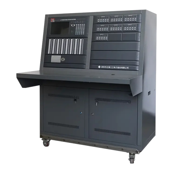
- Page 2 Two models of panels are available as appropriate: JB-QGL-9100E for cabinet-type mounting, and JB-QTL-9100E for piano-type mounting. Since the features and operating interfaces of both panels are similar, here we take the JB-QGL-9100E as an example to specify. Thank you for purchasing the product produced by SHENZHEN FANHAI SANJIANG ELECTRONICS CO LTD! Please be sure to read this user’s manual carefully before using...
-
Page 3: Table Of Contents
Contents Chapter 1 System Overview........................1 1.1 System introduction........................1 1.2 System Features..........................1 1.3 System diagram..........................2 1.4 System components........................3 1.5 Technical specifications......................3 1.5.1 Power supply:........................3 1.5.2 Operating conditions:.......................3 1.5.3 Peripheral devices......................3 Chapter 2 Installation and Dimensions....................4 2.1 Product Appearance and Dimensions..................4 2.2 System installation........................ - Page 4 4.4.6 Disable/enable manual control..................40 4.4.7 Sounder auto/manual..................... 40 4.4.8 Re-coding check......................40 4.4.9 Single point test....................... 41 4.4.10 Single point start/stop....................42 4.4.11 Auto register........................43 4.4.12 Disable current alarms....................44 4.4.13 Query current disablement..................44 4.4.14 Cancel all disablement....................45 4.4.15 Query current delay...................... 45 4.5 History query..........................
-
Page 5: Chapter 1 System Overview
JB-QBL-9116E fire alarm control panel is a new generation of fire alarm control panel issued by Shenzhen Fanhai Sanjiang Electronics Co., Ltd. It is used with other related products of the company to form an integrated and automatic control system, which is perfectly suitable for the application from medium to large-sized fire alarm and fire protection applications. -
Page 6: System Diagram
1.3 System diagram 盘 - 8 6 - 8 6 示 显 : 真 : 灾 热 线 服 务 火 传 按 键 ) / 禁 ( 允 键 按 音 消 消 音 故 障 复 恢 讯 通... -
Page 7: System Components
1.4 System components As shown in Figure 1-1, the fire alarm control system mainly consists of the followings: Main control unit The main control unit is responsible for processing and analyzing the data transmitted from other parts, and commanding, based on results of data analysis, other parts in the system to execute accordingly, such as controlling the buzzer to sound for fire. -
Page 8: Chapter 2 Installation And Dimensions
Chapter 2 Installation and Dimensions 2.1 Product Appearance and Dimensions JB-QTL-9100E Fig 2- 1 Dimensions of JB-QTL-9100E... -
Page 9: System Installation
Printer Cover plate Fig 2- 2 Dimensions of JB-QGL-9100E 2.2 System installation 2.2.1 Items check Before installation, check the field equipment at first. After opening the packing box, check the items inside one by one according to the packing list including installation and operation instructions, fuse, standby screw and key of the control panel, and then, if necessary, check appearance of the cabinet after verification. -
Page 10: Power-On Test
component drop-off or loose due to shipment. 2.2.4 Power-on test After above checks, do power-on test as specified in 2.4.2, and verify whether power supply and basic functions (such as button and indication functions) of the control unit operate normally without connecting any peripheral equipment. -
Page 11: Chapter 3 System Commissioning And Operation
3.2 System operations 3.2.1 Panel functions The front panel layout of JB-QGL-9100E is shown as below: Fig 3- 1 Front panel layout The functions of alarm inquiry and control are involved which are explained as below:... - Page 12 The indicator lights when the panel is in fault or the system Yellow SYS FAULT is not operating as expected. Reserved. SURV. ALARM When a cause&effect is triggered during delay period, the DELAY indicator lights until the end of the delay. The indicator will light when the system detects the fault of POWER Yellow...
- Page 13 AUTO/MANUAL (button with light) In manual status, pressing AUTO/MANUAL to switch to automatic status, meanwhile the button indicator lights; switch to the manual status after pressing again, and the indicator is off. When panels are connected, pressing AUTO/MANUAL on No.1 host in the network will change the auto/manual state of all panels;...
- Page 14 ▲, SELECT, ENTER, ▼ buttons are commonly used at the following situations: Alarm inquiry: Password input: ▲ — scroll upward ▲ — move cursor upward SELECT— number selection SELECT— field selection (Fire, request/feedback, fault) ENTER— confirm ENTER— field selection (Fire, request/feedback, fault) ▼...
-
Page 15: Panel Start-Up
Display current date and time of the system Power state bar Display the current power state of the host by icon, as shown in the figure: Fig 3- 5 States and meaning of icons System info column at right Display operations applied to the panel. 3.2.2 Panel start-up The power supply required for normal operation of the system is AC 220V±20%, 50Hz. - Page 16 Super user, system debugger and system administrator may log in the system by two ways. 1. Log in through standard USB keyboard. Pop up the login window by pressing Ctrl, Alt and Del keys simultaneously (as shown below). Fig 3- 7 Example of USB keyboard 2.
-
Page 17: Special Functional Keys
Attention: Under login state, the system will log out automatically if it is inactive within 10 minutes (no key is pressed and the mouse does not move). Note: Under logout state, the user may only operate "MUTE" and other operations are not allowed. -
Page 18: Chapter 4 System Configuration Details
Chapter 4 System Configuration Details This section will describe operation of the sub-menus related to the system configuration including system setup, bus setup and c&e setup. The following figure is the list of menu setup. Menus CAN-Bus Linkage Operation History Special About System... -
Page 19: Time Setup
4.1.1 Time setup The time setup interface is as follows: enter into proper date and time, click the OK button, and the system will save the time set by the user. Fig 4- 3 Time setup window Note: In the networking system of multiple hosts, as the host time is required to be the same, all hosts in the system will take time of the main panel as criterion. - Page 20 Zone setup: the zone can be named in "position description"; the initialization value in the figure is "zone 1-N". Fig 4- 4 Zone setup window Building setup: the building can be named in "position description"; the initialization value in the figure is "building 1-N". Fig 4- 5 Building setup window Floor setup: press OK button to save the setup and exit;...
-
Page 21: Network Setup
Prompt: The building can be renamed in the "position description" column in the form of building setup, which makes the alarm message easier to read, for example, if building 1 is named as "science building", the alarm message would be changed as follows: Fire alarm at room 28, F8, building 1→Fire alarm at room 28, F8, science building If the location information of each detector or module shall be completely independent, the corresponding position description of each detector or module can be entered at the... - Page 22 and finally click on the corresponding "Register" column on the networked hosts to display "√". Then press OK button to save the setup and exit, otherwise press Cancel button to retain the original setup and exit. Note: The transmission rate set for all hosts in the networking system must be the same! After setup of the networking transmission rate, the host must be restarted to take effect! Prompt: If the host under different rates is connected into the network, no hosts (including other hosts with the same transmission rate) will provide normal communications.
-
Page 23: Password Setup
success rate of communications is relatively low, and the transmission rate shall be reduced or the transmission environment shall be improved. The networking of 20 hosts is achievable on the system. The abnormality of any host in the network will not cause fault of the overall system. All hosts share all alarm messages (including fire alarm, request, feedback and fault) over the network. -
Page 24: Fip/Extender Setup
Note: The users of each level may change passwords of the same and lower levels. For example, the system administrator may change its password and the passwords of all watchmen. However, the system administrator is not allowed to change the password of the system debugger. -
Page 25: Ext.-Connected Fip Setup
The setup window is shown below: Fig 4- 12 Fire indicating panel setup window 2 The following shall be set up for 485 equipment: Type - 485 equipment is divided into the following types: Extender (Extender for FIP) Zone-LCD (zone indicating panel in characters) Bldg-LCD (building indicating panel in characters) Floor-LCD (floor indicating panel in characters) Zone-LED (digital zone indicating panel) -
Page 26: Power Setup
Fig 4- 13 Ext.-connected FIP setup window Modifying method: Register the extender under the “FIP/Extender setup” window. Choose the corresponding extender at the window above and find the address of the FI to be registered and click on the "Register" column to show "√". Choose “type”, “zone”, “building” and “floor” respectively and add information in the “position description”. -
Page 27: Rename System
show "√". Press "OK" button to save the setup and exit, otherwise press "Cancel" button to retain the original setup and exit. Prompt: ”SPRT-01” is a stylus printer defined by the system while “SPRT-02” is a thermal one. Default transmission rate for the thermal printer is 9600BPS while 2400BPS for stylus printer. 4.1.9 Rename system The name of the system can be changed: Fig 4- 16 Window of renaming system... -
Page 28: Detector/Module Setup
Detectors and modules are connected to the system through IO-Board. The panel can manage up to 40 IO-Boards in total. With 2 loops per board and 324 points per loop, the maximum capacity of the system can reach to 25920 points. Choose IO-Board to be registered and click in "register", "... - Page 29 Fig 4- 21 Loop number setup The following section describes the line-by-line sheet setup of detector/module. As setup of the system imitates the spreadsheet of Windows operation interface, most of the operations are completed by the mouse, which operates drop-down box, horizontal scroll bar and vertical scroll bar.
- Page 30 The figure below shows device type setup of detector/module: Fig 4- 23 Device type setup For detectors, the Device Type and Manufacturing Type are generally the same. For modules, the Device Type and Manufacturing Type are usually different, except for the six special modules of manual control button, manual call point, fire hydrant call point, sounder strobe, sounder and strobe whose Device Type and Manufacturing Type are kept the same as detectors.
- Page 31 Fig 4- 25 Zone, building, floor, room number setup Working mode setup of detectors shows below: Fig 4- 26 Work mode setup There are three Work Modes for detectors: Normal, Fast and Slow. It is recommended to use the Normal mode since Fast and Slow modes are adopted under some special applications. The location descriptive information of detector/module is as shown in the following figure.
- Page 32 Fig 4- 27 Position description setup After "detector/module setup" is completed, press "OK" button to save the setup and exit, or press "Cancel" button to retain the original setup and exit. In case of error operation, if data has been altered when pressing “Cancel”, a prompt pops up: Fig 4- 28 System prompt If several devices with consecutive addresses have same features to be set, an alternative to configuring them all individually is to make a batch set.
-
Page 33: Add Device Type
them are ticked) and are set according to floor number and room number of address 1 and options selected in the drop-down list after it (i.e. "same", "ascending order" and "descending order"; "same" by default); if ascending order is checked in the drop-down list, the floor number of equipment at address 1 is 2, the floor number of equipment at address 2 is 3 and the floor number of equipment at address 3 is 4, and so on, which is also suitable for the room number. -
Page 34: Linkage C&E Setup
4.3 Linkage c&e setup The sub-menus under this category show as below: Fig 4- 32 C&E setup menu 4.3.1 System linkage setup The following section gives a brief description of common issues of linkage setup with the system linkage as an example. The setup window is as follows: Fig 4- 33 System linkage setup window The setup interface is divided into 3 areas: condition area, output area and area of optional activation devices. - Page 35 Adding a linkage condition: click on Add button Deleting a linkage condition: click on Del button Viewing or editing the linkage condition on the previous page: click on Prev Viewing or editing the linkage condition on the next page: click on Next Viewing or editing a certain linkage condition: enter serial number of the linkage condition into the text box before "Pg", enter or click on to.
- Page 36 The operation of "delay" drop-down box is as shown in the following figure: Fig 4- 34 Delay setup There are 8 time selections for delay: 0s, 5s, 10s, 30s, 60s, 90s, 120s and 150s. Selection of input type, as follows: Fig 4- 35 Input type selection The 5 types commonly used by the system are presented by check boxes and 4 drop-down selection boxes are given for selection of any equipment type.
- Page 37 Fig 4- 36 Fire quantity selection The default value of linkage alarm is 01, which means the condition is satisfied when any one equipment reports alarm. In some applications, the following linkage relations may be possible due to high reliability requirement of linkage action: At this moment, set the linkage alarm number as 02 and consider the module controlling "fire pump"...
-
Page 38: Zonal Linkage Setup
A complete zonal condition (for example, the room range must be included in a linkage) At least one type of device should be chosen at the condition area Delay time At least one device should be chosen to activate when a linkage condition is met. If the user input these elements incorrectly during setup, the system will deny and present corresponding prompt when OK button is pressed. -
Page 39: Floor Linkage Setup
Fig 4- 39 Building linkage setup The drop-lists of zone, building, floor range are added. The equation above represents the following: Condition Result In building 1 of zone 1: smoke exhaust When the following happens at floor -1 connected to the No.5 module to 23: in loop 1 of IO-board 1 will start Any one of smoke valves activated... - Page 40 Fig 4- 40 Floor linkage - type output The equation above can be explained: If any one of optical smoke detector or heat detector or MCP is triggered, the broadcast and remote alarm devices at the same or immediately above/below floors with the detector or MCP will all be activated.
-
Page 41: Room Linkage Setup
4.3.5 Room linkage setup Fig 4- 42 Room linkage setup For room linkage, start room number and end room number at a certain floor can be selected by drop-down box, which means: When detector or module of any specified type at all rooms with a number between start number and end number at the floor gives an alarm, all modules listed in the output result list will be activated. -
Page 42: Manual Control Panel Setup
4.3.7 Manual control panel setup Manual control panel setup is completely different from other linkages. It connects a direct control button with a module in the loop. The integrated meaning is: direct control button corresponds to a module selected completely controls the start/stop of the module listed in the result list. -
Page 43: Fire Hydrant Setup
Fig 4- 46 Broadcast control panel - manual point setup window 4.3.10 Fire hydrant setup The four/six-wire fire hydrant produced by our company can be used as four-wire fire hydrant and is compatible with the functions of old six-wire fire hydrant. When used as four-wire fire hydrant, the corresponding relation between water pump shall be set by the setting function. -
Page 44: Operation
4.4 Operation The sub-menus under this category show as below: Fig 4- 48 Sub-menus of Operation 4.4.1 Mute 4.4.2 Reset 4.4.3 System test The operation of the above three functions are same with using the functional buttons on the front panel. Refer to the section of “Panel functions”. 4.4.4 H/S control Same function with the button of “H/S CTRL”. -
Page 45: Single Point Test
Fig 4- 49 Re-coding check window Select "Check" to carry out the repeat address check. Now, "Check" and "Back" buttons are disabled. When the check is completed, all repeated addresses in the loop will be displayed. Now it can check again, or exit the repeat address check by pressing "Back". The time-out error will be displayed if repeat value and stop command have not been obtained within 120 sec, and the test shall be carried out again. -
Page 46: Single Point Start/Stop
Fig 4- 51 Single point test - commissioning mode Enter IO-Board number,loop number and the bus address point requiring single point test and click on "OK" button to start the relevant test, and the screen display is as follows: Fig 4- 52 The result of the single point test The curve in the figure represents current state of detector/module. -
Page 47: Auto Register
Fig 4- 53 Select the point to start/stop The user may select one of the module host number, loop number and addresses by drop-down box and click on Start or Stop to carry out corresponding operations; click on Exit button directly to exit out of the dialog box without performing any operation. Click on drop-down button of address number and the system will list addresses of all output or input modules for selection by the user. -
Page 48: Disable Current Alarms
Fig 4- 56 Register result The above figure shows that 5 detectors are registered in the original setting, but only 2 detectors are on-line currently; 10 modules are registered, but only 7 modules are on-line. The figure also prompts warning messages, such as "Press OK to enter setup interface" and "register and manufact type address will be changed", to prompt the user to make choice. -
Page 49: Cancel All Disablement
Fig 4- 58 Current disablement query The entire screen can display 16 disable points; if the total number exceeds 16, click on Prev. and Next to turn page and inquire. Click on Back button to exit the isolation query interface. The disable device query interface is for the user to acknowledge current disable condition of the equipment;... -
Page 50: History Query
History query The query function of this system can be used to inquire various historical messages, which include the sub-items below: Fig 4- 60 Sub-menus of History Each sub-item can access 1000 historical records at most. If historical messages total more than 1000, the system will update automatically and overwrite. -
Page 51: History Fault
4.5.2 History fault The format of each historical fault is as follows: Time Company Equipment Type (Year/Month/Day/ Fire Description Code Fault Type Hour/Minute) 16/03/17 10:18 00101000 Host1 power AC fault power fault Query interface of historical faults is similar to that of historical fire alarms. Fig 4- 62 History fault interface 4.5.3 History linkage The format of each request/feedback information is as follows:... -
Page 52: History Operation
Fig 4- 63 History linkage interface 4.5.4 History operation Historical operations include the operations carried out on the system by the user, such as login, reset and muting. The sub item can be used for inquiring information of the latest 1000 historical operations, with the format of each historical operation as follows: Date Time... -
Page 53: Special
Fig 4- 65 Sub-menus of history deletion The historical deletions can be used to remove historical faults, historical linkage, historical fire alarms and historical operations, and this historical information can be deleted by selecting relevant option. Prompt: Barring special circumstances, the user is not suggested to delete historical records. -
Page 54: Usb Data Loading
If U disk is inserted incorrectly, the system prompt will be as follows: Fig 4- 68 Prompt when U disk is not inserted If U disk is inserted correctly and the remaining storage capacity satisfies the requirement, the system will proceed to copy setup data and historical data into U disk. The system will indicate successful backup after all data are processed completely and the whole process will take 30-60sec. -
Page 55: Bus Check
4.6.3 Bus check Monitor the communication line of the host. Number of sending data packages and number of receiving data on the networked bus will be shown. Number of receiving data packages is relevant to bus communication quality, and meantime number of sending data packages and number of receiving packages on the corresponding bus will differ greatly in case of host fault. -
Page 56: Adjust Lcd Brightness
Fig 4- 74 Statistics interface 4.6.6 Adjust LCD brightness Remind the methods of modifying LCD brightness dynamically and display current LCD brightness. The brightness control via panel must be carried out in this window. Fig 4- 75 Adjust LCD brightness 4.7 About Sub-menus under About show as below: Fig 4- 76 About menu... - Page 57 Fig 4- 77 System version info The current version number shown in the dialog box. The system version can be updated on site. Our company will continuously improve the system, add new functions and be responsible for the real-time version upgrading of projects that have signed maintenance contracts with our company.
-
Page 58: Chapter 5 Alarm Function
Chapter 5 Alarm Function Alarm is the main function of the fire alarm linkage control equipment. The system can recognize, control and drive our company’s bus devices and multi-wire devices, including intelligent detectors and modules. The alarm functions mainly include fire alarm, device linkage and handling and display of various faults. - Page 59 the host screen with corresponding acousto-optic instructions simultaneously given by the indicator light and the buzzer. The alarm interface locks the first alarm message of each alarm type (always exhibits in the first line, not participates in the scroll display). Alarm messages following the first one are in the circular scroll display with an interval of 5 seconds.
- Page 60 8. Activated alarm box Activated alarm box is used to show which type of alarm messages in the alarm interface is under activated status and only such allows manual query operation. Operations can be performed on the alarm interface: Alarm information query: 1....
-
Page 61: Chapter 6 Instruction Of Manual Control Panel
Chapter 6 Instruction of Manual Control Panel Several manual control panels (also known as Fireman Panel) can be included in the system for customer to directly take the control of equipment manually. Each panel (2U panel) includes 30 manual points with 2 LEDs per point: one LED for request to start and one LED for feedback signal from the equipment. -
Page 62: Chapter 7 Instruction Of Multi-Wire Linkage Unit
Chapter 7 Instruction of Multi-wire Linkage Unit Several linkage units can be included in the system. Each unit includes 5 control points and each point includes the following: Start button Feedback indicator Stop button Normal state indicator Start indicator Fault state indicator The figure shown below is three units mounted on this fire alarm control panel, 15 points in total: Fig 7- 1Multi-wire linkage unit The panel number that can be included depends on how many IO-boards in the system. -
Page 63: Chapter 8 Troubleshooting
Chapter 8 Troubleshooting Problem: No action from alarm bells or horn strobes when the system reports a fire. Possible reason and solution: a. Please check whether the H/S indicator on the panel has been lit. b. Whether there is fault message about that alarm bell or horn strobe on the LCD. c. - Page 64 communication distance and low rate, the data packages received are far less than the ones sent during bus quality check, and the host networking is abnormal. The networking of 9100 series host adopts a relevant advanced CAN BUS protocol at the current, which requires serial connection of networked hosts only and prohibits star connection.
-
Page 65: Chapter 9 Annex
Chapter 9 Annex Annex 1: Device type Type/ of alarm equipment: 1. IonD (Ion smoke detector) 2. OptD (Photoelectric smoke detector) 3. HeatD (Heat detector) 4. BeamD (Infrared detector) 5. CombD (Composite detector) 6. ConvIon (Interface ion detector) 7. ConvPhoto (Interface photoelectric detector) 8. - Page 66 Any changes to the product due to the upgrading will not be further notified and the physical product may prevail. The newest version can be required freely from our company. Shenzhen Fanhai Sanjiang Electronics Co., Ltd. possesses the rights of final interpretation and modification!
Need help?
Do you have a question about the JB-QGL-9100E and is the answer not in the manual?
Questions and answers