Table of Contents
Advertisement
Quick Links
Advertisement
Table of Contents

Related Manuals for SEW-Eurodrive M1 N Series


Summary of Contents for SEW-Eurodrive M1 N Series
- Page 1 *29203856_0320* Drive Technology \ Drive Automation \ System Integration \ Services Assembly and Operating Instructions Industrial Gear Units M1..N Series Single-Stage Helical Gear Units Torque Classes from 1.4 kNm to 189 kNm Edition 03/2020 29203856/EN...
- Page 2 SEW-EURODRIVE—Driving the world...
-
Page 3: Table Of Contents
Table of contents Table of contents General information........................ 6 About this documentation .................... 6 Structure of the safety notes ................... 6 Rights to claim under limited warranty ................ 7 Decimal separator in numerical values ................ 8 Product names and trademarks.................. 8 Copyright notice ...................... 8 Safety notes .......................... 9 Preliminary information .................... 9 Duties of the user...................... 9 Target group ........................ 9... - Page 4 Table of contents Important information .................... 39 Prerequisites for installation.................. 41 Installing the gear unit.................... 42 Filling gear units with oil / delivered without oil fill (standard) ........ 47 Gear units delivered with oil fill (option) ................ 48 Gear units with solid shaft..................... 49 Mounting tolerances...................... 50 5.10 Mounting the couplings .................... 52 5.11...
- Page 5 Table of contents Troubleshooting information .................. 94 Service .......................... 94 Possible malfunctions/remedy .................. 95 Waste disposal...................... 97 Address list .......................... 98 Assembly and Operating Instructions – M1..N Series Single-Stage Helical Gear Units...
-
Page 6: General Information
General information About this documentation General information About this documentation The documentation at hand is the original. This documentation is an integral part of the product. The documentation is intended for all employees who perform work on the product. Make sure this documentation is accessible and legible. Ensure that persons respon- sible for the systems and their operation as well as persons who work on the product independently have read through the documentation carefully and understood it. -
Page 7: Rights To Claim Under Limited Warranty
General information Rights to claim under limited warranty Meaning of the hazard symbols The hazard symbols in the safety notes have the following meaning: Hazard symbol Meaning General hazard Warning of dangerous electrical voltage Warning of hot surfaces Warning about suspended load Warning of automatic restart 1.2.3 Structure of embedded safety notes... -
Page 8: Decimal Separator In Numerical Values
General information Decimal separator in numerical values Decimal separator in numerical values In this document, a period is used to indicate the decimal separator. Example: 30.5 kg Product names and trademarks The brands and product names in this documentation are trademarks or registered trademarks of their respective titleholders. -
Page 9: Safety Notes
Safety notes Preliminary information Safety notes Preliminary information The following general safety notes serve the purpose of preventing injury to persons and damage to property. They primarily apply to the use of products described in this documentation. If you use additional components, also observe the relevant warning and safety notes. -
Page 10: Designated Use
Safety notes Designated use Specialist for elec- Any electrotechnical work may be performed only by electrically skilled persons with a trotechnical work suitable education. Electrically skilled persons in the context of this documentation are persons who are familiar with electrical installation, startup, troubleshooting, and main- tenance of the product who possess the following qualifications: •... -
Page 11: Safety Symbols On The Gear Unit
Safety notes Safety symbols on the gear unit Safety symbols on the gear unit CAUTION Safety/caution signs and safety symbols can become dirty or illegible over time. Risk of injury due to illegible symbols. • Always make sure that safety, warning, and operating notes are legible. •... - Page 12 Safety notes Safety symbols on the gear unit Safety symbols Meaning Indicates the oil return and serves to locate the connection op- tion. Indicates the position of the temperature sensor/temperature switch. ° Indicates the grease drain plug and serves to locate the grease drain.
- Page 13 Safety notes Safety symbols on the gear unit After startup, you may remove the following labels from the gear unit. Meaning The brake is not set at the factory. VORSICHT NOTICE ATTENTION PRECAUCIÓN VOORZICHTIG OSTROŻNIE Die Bremse ist ab Werk nicht The brake has not been set at eingestellt.
- Page 14 Safety notes Safety symbols on the gear unit Meaning The coupling is delivered without oil. VORSICHT NOTICE ATTENTION PRECAUCIÓN VOORZICHTIG OSTROŻNIE Kupplung wird ohne Öl geliefert. Coupling delivered without oil Mögliche Sachschäden! Possible damage to property. • Vor der Inbetriebnahme Kupplung •...
- Page 15 Safety notes Safety symbols on the gear unit Meaning The gear unit is delivered without oil. VORSICHT NOTICE ATTENTION PRECAUCIÓN VOORZICHTIG OSTROŻNIE Getriebe wird ohne Öl geliefert. Gear unit is delivered without oil. Mögliche Sachschäden! Potential damage to property! • Vor der Inbetriebnahme Ölbefüllung •...
-
Page 16: Symbols On The Dimension Sheet
Safety notes Symbols on the dimension sheet Symbols on the dimension sheet The symbols on the dimension sheet must be observed. They have the following meaning: Symbols Meaning Indicates the oil filling location. Indicates the oil drain. Indicates the position of the breather. Indicates the position of the inspection cover. -
Page 17: Symbols On The Packaging
Safety notes Symbols on the packaging Symbols on the packaging The symbols on the packaging must be observed. They have the following meaning: Protect Fasten Hand hooks Fragile from heat prohibited here Keep dry Center of gravity 1811486091 Assembly and Operating Instructions – M1..N Series Single-Stage Helical Gear Units... -
Page 18: Transport
Safety notes Transport Transport 2.9.1 General information WARNING Suspended loads can fall. Severe or fatal injuries. • Do not stand under the suspended load. • Secure the danger zone. • Use suitable, sufficiently rated, and undamaged handling equipment. • Consider the gear unit dimensions, the center of gravity, and the weight that has to be moved when selecting lifting equipment or crane (see dimension drawing). - Page 19 Safety notes Transport NOTICE Improper transport may cause damage to the gear unit. Possible damage to property. • Observe the following information. • Inspect the shipment for any possible transport damage as soon as you receive the delivery. Inform the shipping company immediately about any damage. In the event of damage, do not start up the gear unit.
-
Page 20: Storage And Transport Conditions
Safety notes Storage and transport conditions 2.10 Storage and transport conditions The gear units can be provided with the following protection and packaging types de- pending on the storage and transport conditions. 2.10.1 Internal conservation Standard corrosion protection After the test run, the test oil fill is drained out of the gear unit. The remaining oil film protects the gear unit against corrosion for a limited period of time. - Page 21 Max. 3 years with regular in- protection spection and checking for in- tactness. long-term packaging INFORMATION If stored in tropical zones, provide for sufficient protection against insect damage. Contact SEW-EURODRIVE for differing requirements. Assembly and Operating Instructions – M1..N Series Single-Stage Helical Gear Units...
-
Page 22: Gear Unit Structure
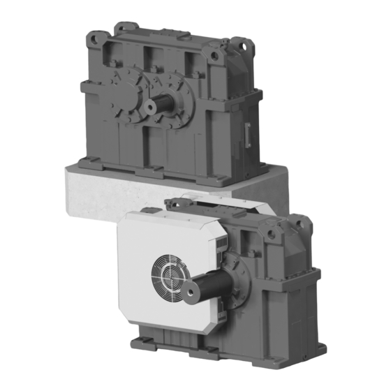
Gear unit structure Overview of gear unit and mount-on components Gear unit structure Overview of gear unit and mount-on components The M1..N series consists of single-stage helical gear units. The following figure shows the unit structure. 12932308235 Two-piece gear unit housing Oil level glass Inspection cover Oil drain... -
Page 23: Nameplate
Gear unit structure Nameplate Nameplate The following example shows the structure of the nameplate. SEW-EURODRIVE 76646 Bruchsal/Germany M1PSF50N Type 01.1234567812.0001.06 4,0417 min. nom. max. PK1 kW 2,93 7230 1500 °C 0...40 1743 895 0.13 Made in SEW – Finnland Year 2019 Qty. -
Page 24: Type Designation
Gear unit structure Type designation Type designation The type designation is set up as follows: Example: M1PSF50 /N Industrial gear unit series Number of gear unit stages Gear unit type, P = helical gear unit, parallel shafts Output shaft type, S = solid shaft Helical gear units Gear unit mounting, F = foot mounting Gear unit size (10, 20, 30, 40, 50, 60, 70, 80, 90,... -
Page 25: Shaft Positions
Gear unit structure Shaft positions Shaft positions The shaft positions (1 to 4) shown in the following figure apply to solid output shafts (LSS). 12868535307 Directions of rotation The direction of rotation of the output shaft is defined as follows: 12868467595 Assembly and Operating Instructions –... -
Page 26: Coating And Surface Protection Systems
Gear unit structure Coating and surface protection systems Coating and surface protection systems Gear units are available with surface protection OS1, OS2, and OS3. The following table gives an overview of coating and surface protection systems. SEW design OS 1 OS 2 OS 3 Medium High... -
Page 27: Lubrication
Gear unit structure Lubrication Lubrication For M1..N series gear units in horizontal mounting position, splash lubrication or pres- sure lubrication is usually used. 3.8.1 Splash lubrication Splash lubrication is used for M1..N series industrial gear units. The oil level is low. Parts that are not immersed in the oil bath, such as the driving gear wheel and bearing parts, are lubricated by splashing oil. -
Page 28: Accessories
Gear unit structure Accessories Accessories The following section describes the accessories for the several types of lubrication. INFORMATION The position of the accessory may vary depending on the gear unit version and the gear unit size. 3.9.1 General accessories The following figure shows the general accessories. 12869289483 Breather Oil drain... -
Page 29: Design Of Options And Accessories
Design of options and accessories Shaft end pump Design of options and accessories Shaft end pump The maintenance-free shaft end pump [1] can be used for both directions of rotation. 9007212223271819 INFORMATION For operation with variable input speeds, consult SEW‑EURODRIVE. The standard scope of delivery comprises: •... -
Page 30: Motor Pump
Design of options and accessories Motor pump Motor pump The motor pump [1] is suitable for operation in both directions of rotation. 31256464907 The motor pump consists of the following: • Pump motor • Coupling between pump motor and gear pump •... -
Page 31: Fan
Design of options and accessories A fan may be mounted to raise the thermal rating or when the ambient conditions change after gear unit startup. The direction of rotation of the gear unit does not influ- ence the operation of the fan. The following mounting options are possible: 12874998283 Mounting on the input end - HSS... -
Page 32: Cooling Coil
Design of options and accessories Cooling coil Cooling coil The cooling coil increases the thermal rating of the gear unit by cooling the oil bath. The cooling coil is placed in the oil bath of the gear unit. The operator must ensure that the minimum flow rate specified in the order documents is met. -
Page 33: Oil Heater
Design of options and accessories Oil heater Oil heater An oil heater may be required to ensure lubrication during a cold gear unit startup when the ambient temperature is low. Oil heating is required to ensure lubrication during startup at low ambient temperature (e.g. -
Page 34: Oil-Air Cooler For Pressure Lubrication
Design of options and accessories Oil-air cooler for pressure lubrication Oil-air cooler for pressure lubrication INFORMATION The unit structure is described in the manufacturer's documentation of the oil-air cooler for pressure lubrication. Oil-water cooler for pressure lubrication INFORMATION The unit structure is described in the manufacturer's documentation of the oil-water cooler for pressure lubrication. -
Page 35: Customer-Provided Cooling Systems And Lubrication Systems
Design of options and accessories Customer-provided cooling systems and lubrication systems 4.10 Customer-provided cooling systems and lubrication systems In case the customer orders a gear unit for which SEWEURODRIVE recommends us- ing pressure lubrication and/or an additional cooling system, refer to this chapter for guidelines on how to select the components. - Page 36 Design of options and accessories Customer-provided cooling systems and lubrication systems 4.10.2 Typical structure of pressure lubrication with oil-water cooler [RB] [RA] [A5] [A3] [A4] [A1] [A2] 9007230527516043 Standard design Optional design Pump Thermometer Filter Pressure relief valve Oil-water cooler [A2] Electrical indicator of filter clogging Pressure gauge [A3] Temperature monitor...
-
Page 37: Thermostat Valve
Design of options and accessories Thermostat valve 4.11 Thermostat valve The valve serves for regulation of the water flow in the oil-water cooler or in the cool- ing coil of the gear unit. 31295050379 Button Spring actuator Spindle Push rod Sensor Assembly and Operating Instructions –... -
Page 38: Installation/Assembly
Installation/assembly Required tools/resources Installation/assembly Required tools/resources Not included in the delivery: • Set of wrenches • Torque wrench • Mounting device • Compensation elements (shims, spacer rings), if necessary • Fasteners for input and output elements ® • Lubricant, e.g. NOCO fluid from SEW →... -
Page 39: Important Information
Installation/assembly Important information Important information Read the following notes prior to installation/mounting. WARNING Risk of crushing if the drive starts up unintentionally. Severe or fatal injuries. • Work on the gear unit only when the machine is not in use. Secure the drive unit against unintentional power-up. - Page 40 • Only authorized personnel may assemble gear head units with motors and ad- apters. Consult SEW-EURODRIVE. • Do not weld anywhere on the drive. Do not use the drive as a ground point for welding work. Welding may destroy gearing parts and bearings.
-
Page 41: Prerequisites For Installation
Installation/assembly Prerequisites for installation Prerequisites for installation Check that the following conditions have been met: • The information on the motor's nameplate must match the voltage supply system. • The drive has not been damaged during transportation or storage. • The ambient temperature matches the information in the order documents. -
Page 42: Installing The Gear Unit
Installation/assembly Installing the gear unit Installing the gear unit WARNING Danger due to insufficient attachment options on the part of the operator. Severe or fatal injuries. • Make sure that there are sufficient and suitable attachment options for the gear unit at the operator's machine before mounting the gear unit to the operator's ma- chine. - Page 43 Installation/assembly Installing the gear unit Example 12868470283 [1] Stud bolts with nut and hex head screw Hex nut [2] Shims Foundation bolt [3] Hex nut Base support [4] Foundation support Tightening torques Size Bolt/nut Tightening torque M1..N Strength class 6.8 [Nm] 1090 1900...
- Page 44 Installation/assembly Installing the gear unit 5.5.2 Mounting gear units with solid shaft INFORMATION Before mounting the gear unit, check the dimensions of the foundation. For detailed information, refer to chapter "Gear unit foundation" (→ 2 42) and the dimension sheets in your order documents. Assemble the gear unit in the following order: 1.
- Page 45 Installation/assembly Installing the gear unit Mounting accuracy when aligning 12868472971 When aligning the gear unit, make sure that the mounting tolerances for the flatness of the foundation are not exceeded (y values in the following table). If necessary, use shims [1] to align the gear unit on the foundation plate. [mm] [mm] <...
- Page 46 Installation/assembly Installing the gear unit 5.5.3 Tightening torques: Retaining screws of gear unit mount-on parts Tighten the screws of gear unit mount-on parts and protection covers using the follow- ing tightening torque. INFORMATION The tightening torque does not apply to mounting types such as rigid flange coupling etc.
-
Page 47: Filling Gear Units With Oil / Delivered Without Oil Fill (Standard)
Installation/assembly Filling gear units with oil / delivered without oil fill (standard) Filling gear units with oil / delivered without oil fill (standard) 5.6.1 General information The gear unit is delivered without oil fill as standard. WARNING Risk of crushing if the drive starts up unintentionally. Severe or fatal injuries. -
Page 48: Gear Units Delivered With Oil Fill (Option)
Installation/assembly Gear units delivered with oil fill (option) Gear units delivered with oil fill (option) NOTICE Improper startup can result in damage to the gear unit. Possible damage to property. • It is important that gear units with shaft end pump, motor pump or customer-in- stalled cooling system are vented before taking them into operation the first time. -
Page 49: Gear Units With Solid Shaft
Installation/assembly Gear units with solid shaft Gear units with solid shaft 5.8.1 Mounting input and output components Observe the notes in chapter "Important information" (→ 2 39). NOTICE Bearing, housings, or shafts may be damaged due to improper assembly. Possible damage to property. •... -
Page 50: Mounting Tolerances
Installation/assembly Mounting tolerances Mounting tolerances Adjust the following misalignments according to the coupling manufacturer's specifica- tions when mounting couplings. a) Maximum and minimum clearance b) Axial misalignment c) Angular misalignment 211395595 The following table shows various methods for measuring the differing tolerances. Measuring Angular offset Axis offset... - Page 51 Installation/assembly Mounting tolerances Measuring Angular offset Axis offset instruments Micrometer dial 899597451 A prerequisite for this measuring method is The following figure shows the how to mea- that there is no axial play in the shaft bear- sure axial offset using a more accurate mea- ings when the shafts rotate.
-
Page 52: Mounting The Couplings
Installation/assembly Mounting the couplings 5.10 Mounting the couplings 5.10.1 ROTEX coupling 25485508747 Design of the ROTEX coupling Coupling hub Girth gear The low-maintenance, elastic ROTEX coupling is capable of compensating radial and angular misalignment. Careful and exact alignment of the shaft ensures long service life of the coupling. - Page 53 Installation/assembly Mounting the couplings Mounting the coupling halves onto the shaft NOTICE Improper assembly can damage the gear unit. Possible damage to property • The shaft distance must be strictly observed (dimension E) to ensure axial play of the coupling. 25486974091 Mounting dimensions Set screw...
-
Page 54: Shaft End Pump /Shp
Installation/assembly Shaft end pump /SHP 5.11 Shaft end pump /SHP Intake and delivery pipe/hose are connected independently from the shaft's direction of rotation. This connection must not be changed. 12868532875 Plug connector [SUC] Suction pipe [PRE] Pressure pipe If the shaft end pump does not build up pressure within 10 seconds after the gear unit has been started, proceed as follows: 1. -
Page 55: Fan
Installation/assembly 5.13 A fan can be mounted if the projected thermal power of the gear unit is exceeded. The direction of rotation of the gear unit does not influence the operation of the fan. Observe the following notes if you use a fan: •... -
Page 56: Cooling Coil
Installation/assembly Cooling coil 5.14 Cooling coil 5.14.1 Notes on connection/installation NOTICE Improper mounting of the cooling coil may result in damage to the gear unit. Possible damage to property. • Observe the following notes: • Using thread seal tape on the pipe threads will increase the resistance between the connecting parts. - Page 57 Installation/assembly Cooling coil 5.14.2 Requirements on the water quality INFORMATION Contact SEW‑EURODRIVE if you use cooling media such as brackish water or pro- cess water. The following requirements on the water quality are recommendations. In exceptional cases, certain concentrations of substances of content might cause unforeseen reac- tions.
- Page 58 Installation/assembly Cooling coil Cooling water assessment based on water substances The following table provides an overview of the resistance of copper-nickel pipes against substances in non-potable water. Assessment criterion Approximate concentration Evaluation mg/l CuNi10Fe1Mn < 6 pH value 6 to 9 >...
-
Page 59: Oil-Water Cooler For Pressure Lubrication
Installation/assembly Oil-water cooler for pressure lubrication • Often very contaminated. • A water analysis is necessary for assessment. Salt water • We recommend using brass pipes or copper nickel pipes. Brackish water • We recommend using copper nickel pipes. • Mixture of sea water and river water. -
Page 60: Oil Heater
Installation/assembly Oil heater 5.17 Oil heater WARNING Danger of electric shock. Severe or fatal injuries. • De-energize the oil heater before you start working on the unit. • Secure the oil heater against unintended power-up. NOTICE Improper installation of the oil heater may result in damage to the gear unit. Possible damage to property. - Page 61 Installation/assembly Oil heater 5.17.1 Activation / deactivation behavior • The oil heater is activated when the factory set temperature is reached. This tem- perature setpoint depends on the following factors: – With splash lubrication/bath lubrication: The pour point of the used oil –...
- Page 62 Installation/assembly Oil heater 5.17.3 Electrical connection resistor element Wiring examples with 230 / 400 V supply voltage 25540687499 1-phase Voltage 230 V Phase voltage 230 V Line voltage 400 V Resistor element voltage 230 V 25540691083 3-phase / star connection Voltage 230/400 V Phase voltage 230 V Line voltage 400 V...
- Page 63 Installation/assembly Oil heater 5.17.4 Basic structure of thermostat 5-16-5_figure1: Basic thermostat structure (example) Adjustment knob Capillary tube length up to 10 m Degree of protection IP66 (IP54 in units with external reset) Stainless steel bellows 2 × PG 13.5 for cable diameter 6 mm – 14 mm Polyamide housing SPDT contact system Interchangeable Thermostat RT...
- Page 64 Installation/assembly Oil heater Thermostat RT Alternating current: AC-1: 10 A, 400 V Connection data AC-3: 4 A, 400 V AC-15: 3 A, 400 V Direct current: DC-13: 12 W, 230 V Contact material: AgCdO Cable entry 2 PG 13.5 for cable diameter of 6 – 14 mm IP66 acc. to IEC 529 and EN 60529, IP54 for units with external reset. The thermostat housing is Degree of protection made of bakelite according to DIN 53470, the cover is made of polyamide.
- Page 65 Installation/assembly Oil heater °C °C 25544698507 5-16-7_figure2: Nomogram of the included differential Setting range Obtained differential Differential setting Assembly and Operating Instructions – M1..N Series Single-Stage Helical Gear Units...
-
Page 66: Temperature Sensor /Pt100
Installation/assembly Temperature sensor /PT100 5.18 Temperature sensor /PT100 5.18.1 Dimensions PG9, PG11 G1/2" 31294984971 5.18.2 Electrical connection 359158539 [1][2] Resistor element connection 5.18.3 Technical data • Design with thermometer pocket and changeable measuring insert • Sensor tolerance in K ± (0.3 + 0.005 × T), (corresponds to DIN IEC 751 class B), T = Oil temperature in °C •... -
Page 67: Spm Adapter
Installation/assembly SPM adapter 5.19 SPM adapter 5.19.1 Nipple 32000 and cap 81025 Dimensions of the SPM adapter: g = M8 L = 24, 113, 202, 291 [mm] 12936224907 5.19.2 Sensor 40000 and connection piece 13008 to be connected Dimensions of the SPM adapter with sensor: g = M8 L = 17, 106, 195, 284 [mm] 12936227339... - Page 68 Installation/assembly SPM adapter 5.19.4 Mounting the shock pulse sensor 12936229771 To mount the shock pulse sensor onto the SPM adapters, proceed as follows: 1. Check if the SPM adapter [1] is tightly secured (tightening torque: 15 Nm). 2. Remove the protection cap of the SPM adapter [1]. 3.
-
Page 69: Thermostat Valve
Installation/assembly Thermostat valve 5.20 Thermostat valve 5.20.1 Installation Rise the pipe after installation by manually opening the valve, in order to remove con- taminations or dirt. Insert 2 screwdrivers through the 2 openings in the setting unit of the valve. Push the spring cup upward to open the valve and allow the flow. 31295056139 5.20.2 Settings... - Page 70 Installation/assembly Thermostat valve 5.20.3 Technical data Technical data Maximum working pressure 10 bar Minimum working pressure 2 bar Maximum presser difference 7 bar Maximum water temperature 25 °C (40 °C) 1) When the water is used for the lubrication unit or the cooling coil. Assembly and Operating Instructions –...
-
Page 71: Startup
Startup Gear unit startup Startup Gear unit startup Read the following notes prior to startup. WARNING Risk of crushing if the drive starts up unintentionally. Severe or fatal injuries. • Work on the gear unit only when the machine is not in use. Secure the drive unit against unintentional power-up. - Page 72 Startup Gear unit startup • Fill the gear unit with the oil grade specified on the nameplate. The oil quantity specified on the nameplate is an approximate quantity. The markings on the oil dipstick are the decisive indicators for the oil quantity to be filled into the unit. For additional information, refer to the chapters "Checking the oil level" (→ 2 81) and "Changing the oil" (→ 2 83).
- Page 73 Gear unit startup 6.1.1 Run-in period SEW-EURODRIVE recommends running-in the gear unit as the first phase of startup. Increase load and revolutions up to maximum level in 2 to 3 steps. The run-in phase takes approx. 10 hours. Note the following during the running-in phase: •...
-
Page 74: Motor Pump
Startup Motor pump Motor pump 6.2.1 Notes NOTICE Improper startup of gear units with pressure lubrication can damage the gear unit. Possible damage to property. • Note the following • Do not start up the gear unit if the pressure switch is not connected. •... -
Page 75: External Cooling And Lubrication Systems
Startup External cooling and lubrication systems External cooling and lubrication systems INFORMATION If the gear unit is cooled and lubricated via an external cooling and lubrication sys- tem, the gear unit must not be operated without these systems. For gear units with oil-water cooling system and oil-air cooling system, observe the separate operating instructions. -
Page 76: Shutting Down Gear Units
Startup Shutting down gear units Shutting down gear units WARNING Risk of crushing if the drive starts up unintentionally. Severe or fatal injuries. • Work on the gear unit only when the machine is not in use. Secure the drive unit against unintentional power-up. -
Page 77: Inspection/Maintenance
Inspection/maintenance Preliminary work regarding inspection and maintenance Inspection/maintenance Preliminary work regarding inspection and maintenance Observe the following notes before you start with inspection/maintenance work. WARNING Risk of crushing if the drive starts up unintentionally. Severe or fatal injuries. • Work on the gear unit only when the machine is not in use. Secure the drive unit against unintentional power-up. - Page 78 Inspection/maintenance Preliminary work regarding inspection and maintenance CAUTION Danger due to leakage of lubricant. Injuries. • Remove any dripping oil immediately with oil binding agent. NOTICE Filling in the wrong oil may result in significantly different lubricant characteristics. Possible damage to property. •...
-
Page 79: Inspection And Maintenance Intervals
Inspection/maintenance Inspection and maintenance intervals Inspection and maintenance intervals Adhere to the following inspection and maintenance intervals: Time interval What to do? • Daily • Check the housing temperature at the bearing housing of the HSS: – Mineral oil: max. 90 °C –... -
Page 80: Lubricant Change Intervals
Inspection/maintenance Lubricant change intervals Lubricant change intervals It might be necessary to change the oil more frequently when using special designs or under more severe/aggressive ambient conditions. INFORMATION Mineral CLP lubricants and synthetic polyalphaolefin-based (PAO) lubricants are used for lubrication. The synthetic lubricant CLP HC (according to DIN 51502) shown in the following illustration corresponds to the PAO oils. -
Page 81: Checking The Oil Level
Inspection/maintenance Checking the oil level Checking the oil level 7.4.1 General information Note the following when checking the oil level. NOTICE Improper checking of the oil level may result in damage to the gear unit. Possible damage to property. • Check the oil level only when the gear unit has cooled down and is at a standstill. -
Page 82: Checking The Oil Consistency
Inspection/maintenance Checking the oil consistency Oil dipstick (optional) Observe the notes in chapter "Preliminary work regarding inspection and mainte- nance" (→ 2 77). 1. Unscrew the oil dipstick and remove it. 2. Clean the oil dipstick and re-insert it by pushing it into the gear unit up to the stop. Do not screw in the oil dipstick using force). -
Page 83: Changing The Oil
Inspection/maintenance Changing the oil Changing the oil 7.6.1 Notes Observe the following when changing the oil. WARNING Risk of burns due to hot gear unit and hot gear unit oil. Serious injury. • Let the gear unit cool down before you start working on it. •... - Page 84 Inspection/maintenance Changing the oil • Use a filling filter to fill the oil into the gear unit (max. filter mesh 25 µm). • Remove any dripping oil immediately with oil binding agent. Dispose of the used oil in accordance with the applicable regulations. 7.6.2 Procedure 12869289483...
-
Page 85: Motor Pump
Inspection/maintenance Motor pump INFORMATION Remove any dripping oil immediately with oil binding agent. Motor pump INFORMATION • Read the separate operating instructions regarding the "Motor pump" first before beginning inspection/maintenance work. • Observe the notes in chapter "Preliminary work for inspection and mainte- nance" (→ 2 77). -
Page 86: Oil Heater
Inspection/maintenance Oil heater 7.10 Oil heater WARNING Danger of electric shock. Severe or fatal injuries. • De-energize the oil heater before you start working on the unit. • Secure the oil heater against unintended power-up. Observe the notes in chapter "Preliminary work regarding inspection and mainte- nance" (→ 2 77). -
Page 87: Refilling Sealing Grease
Inspection/maintenance Refilling sealing grease 7.11 Refilling sealing grease WARNING Risk of crushing due to rotating parts. Severe or fatal injuries. • Make sure to provide for sufficient safety measures for relubrication. Observe the notes in chapter "Preliminary work regarding inspection and mainte- nance" (→ 2 77). -
Page 88: Lubricants
Lubricants Guidelines for selecting oil and grease Lubricants Guidelines for selecting oil and grease 8.1.1 Lubricating oils These instructions apply to the following conditions: • Ambient temperature range of -30 °C – +40 °C • Actual maximum pitch line speed below 35 m/s • Lubrication: Pressure, bath or splash lubrication In addition to viscosity class ISO VG, the oil must also contain an anti-wear additive, corrosion protection additive, antioxidant additive, and anti-foam additive. - Page 89 Slow-running gear units If the pitch line speed at the lowest stage is slower than 1m/s (n < 15 1/min), the gear unit is operating in the limit lubrication range. SEW-EURODRIVE recommends the fol- lowing: • Using mineral oils wit EP and wear-protection additives.
-
Page 90: Lubricant Table
Lubricants Lubricant table Lubricant table NOTICE Selecting improper lubricants may damage the gear unit. Possible damage to property. • Contact SEW‑EURODRIVE if you operate the unit under extreme conditions, such as cold, heat, or if the operating conditions have changed since project planning. - Page 91 Lubricants Lubricant table 470490505 9007212393306763 Assembly and Operating Instructions – M1..N Series Single-Stage Helical Gear Units...
-
Page 92: Lubricant Fill Quantities For Horizontal Gear Units In M1 Mounting Position
Lubricants Lubricant fill quantities for horizontal gear units in M1 mounting position Lubricant fill quantities for horizontal gear units in M1 mounting position INFORMATION The specified fill quantities are guide values. The exact values vary depending on the number of gear stages and gear ratio. The oil supply system might influence the oil level. -
Page 93: Sealing Greases / Bearing Greases
Lubricants Sealing greases / bearing greases Sealing greases / bearing greases The table shows the grease types recommended by SEW‑EURODRIVE for operating temperatures from -40 °C to 100 °C. Manufacturer Grease Group Fuchs Renolit CX TOM 15 OEM Group 1 Energrease LS-EP 2 Castrol Longtime PD 2 Castrol... -
Page 94: Malfunctions
Malfunctions Troubleshooting information Malfunctions Troubleshooting information Read the following notes before you proceed with troubleshooting. WARNING Risk of crushing if the drive starts up unintentionally. Severe or fatal injuries. • De-energize the motor before you start working on the unit. •... -
Page 95: Possible Malfunctions/Remedy
Malfunctions Possible malfunctions/remedy Possible malfunctions/remedy Fault Possible cause Measure Unusual, regular run- • Meshing/grinding noise: Bearing • Check oil consistency, change bearings damage ning noise • Knocking noise: Irregularity in the • Consult SEW‑EURODRIVE gearing • Deformation of the housing upon •... - Page 96 Malfunctions Possible malfunctions/remedy Fault Possible cause Measure Oil leaking • Seal not tight at: • Tighten the bolts on the respective cover. Observe the gear unit. Contact • From cover plate – Cover plate SEW‑EURODRIVE if oil is still leaking •...
-
Page 97: Waste Disposal
Malfunctions Waste disposal Waste disposal Dispose of the product and all parts separately in accordance with their material struc- ture and the national regulations. Put the product through a recycling process or con- tact a specialist waste disposal company. If possible, divide the product into the follow- ing categories: •... -
Page 98: Address List
Condomínio Industrial Conpark montadora.rc@sew.com.br Caixa Postal: 327 13501-600 – Rio Claro / SP Joinville SEW-EURODRIVE Brasil Ltda. Jvl / Ind Tel. +55 47 3027-6886 Rua Dona Francisca, 12.346 – Pirabeiraba Fax +55 47 3027-6888 89239-270 – Joinville / SC filial.sc@sew.com.br... - Page 99 Ancienne Route Bonabéri Fax +237 233 39 02 10 P.O. Box sew@sew-eurodrive-cm B.P 8674 Douala-Cameroun Canada Assembly Toronto SEW-EURODRIVE CO. OF CANADA LTD. Tel. +1 905 791-1553 Sales 210 Walker Drive Fax +1 905 791-2999 Service Bramalea, ON L6T 3W1 http://www.sew-eurodrive.ca l.watson@sew-eurodrive.ca Vancouver SEW-EURODRIVE CO.
- Page 100 Address list Colombia Assembly Bogota SEW-EURODRIVE COLOMBIA LTDA. Tel. +57 1 54750-50 Sales Calle 17 No. 132-18 Fax +57 1 54750-44 Service Interior 2 Bodega 6, Manzana B http://www.sew-eurodrive.com.co Santafé de Bogotá sew@sew-eurodrive.com.co Croatia Sales Zagreb KOMPEKS d. o. o.
- Page 101 Graben SEW-EURODRIVE GmbH & Co KG Tel. +49 7251 75-0 Ernst-Blickle-Straße 1 Fax +49 7251-2970 76676 Graben-Neudorf Östringen SEW-EURODRIVE GmbH & Co KG, Werk Tel. +49 7253 9254-0 Östringen Fax +49 7253 9254-90 Franz-Gurk-Straße 2 oestringen@sew-eurodrive.de 76684 Östringen Service Competence Mechanics / SEW-EURODRIVE GmbH &...
- Page 102 Address list Germany Saarland SEW-EURODRIVE GmbH & Co KG Tel. +49 6831 48946 10 Gottlieb-Daimler-Straße 4 Fax +49 6831 48946 13 66773 Schwalbach Saar – Hülzweiler dc-saarland@sew-eurodrive.de SEW-EURODRIVE GmbH & Co KG Tel. +49 7348 9885-0 Dieselstraße 18 Fax +49 7348 9885-90 89160 Dornstadt dc-ulm@sew-eurodrive.de...
- Page 103 Ahofer Str 34B / 228 Fax +972 3 5599512 58858 Holon http://www.liraz-handasa.co.il office@liraz-handasa.co.il Italy Assembly Milan SEW-EURODRIVE S.a.s. di SEW S.r.l. & Co. Tel. +39 02 96 980229 Sales Via Bernini,12 Fax +39 02 96 980 999 Service 20020 Solaro (Milano) http://www.sew-eurodrive.it milano@sew-eurodrive.it...
- Page 104 No. 95, Jalan Seroja 39, Taman Johor Jaya Fax +60 7 3541404 Service 81000 Johor Bahru, Johor sales@sew-eurodrive.com.my West Malaysia Mexico Assembly Quéretaro SEW-EURODRIVE MEXICO S.A. de C.V. Tel. +52 442 1030-300 Sales SEM-981118-M93 Fax +52 442 1030-301 Service Tequisquiapan No. 102 http://www.sew-eurodrive.com.mx Parque Industrial Quéretaro scmexico@seweurodrive.com.mx...
- Page 105 Address list New Zealand Assembly Auckland SEW-EURODRIVE NEW ZEALAND LTD. Tel. +64 9 2745627 Sales P.O. Box 58-428 Fax +64 9 2740165 Service 82 Greenmount drive http://www.sew-eurodrive.co.nz East Tamaki Auckland sales@sew-eurodrive.co.nz Christchurch SEW-EURODRIVE NEW ZEALAND LTD. Tel. +64 3 384-6251...
- Page 106 Tel. +386 3 490 83-20 Service UI. XIV. divizije 14 Fax +386 3 490 83-21 3000 Celje pakman@siol.net South Africa Assembly Johannesburg SEW-EURODRIVE (PROPRIETARY) LIMITED Tel. +27 11 248-7000 Sales Eurodrive House Fax +27 11 248-7289 Service Cnr. Adcock Ingram and Aerodrome Roads http://www.sew.co.za Aeroton Ext.
- Page 107 Address list South Korea Busan SEW-EURODRIVE KOREA CO., LTD. Tel. +82 51 832-0204 28, Noksansandan 262-ro 50beon-gil, Fax +82 51 832-0230 Gangseo-gu, Busan, Zip 618-820 Spain Assembly Bilbao SEW-EURODRIVE ESPAÑA, S.L. Tel. +34 94 43184-70 Sales Parque Tecnológico, Edificio, 302 http://www.sew-eurodrive.es...
- Page 108 Wellford, S.C. 29385 IGOrders@seweurodrive.com Additional addresses for service provided on request! Vietnam Sales Ho Chi Minh SEW-EURODRIVE PTE. LTD. RO at Hochim- Tel. +84 937 299 700 City inh City Floor 8, KV I, Loyal building, 151-151 Bis Vo huytam.phan@sew-eurodrive.com...
- Page 112 SEW-EURODRIVE—Driving the world SEW-EURODRIVE GmbH & Co KG Ernst-Blickle-Str. 42 76646 BRUCHSAL GERMANY Tel. +49 7251 75-0 Fax +49 7251 75-1970 sew@sew-eurodrive.com www.sew-eurodrive.com...
Need help?
Do you have a question about the M1 N Series and is the answer not in the manual?
Questions and answers