Table of Contents
Advertisement
Quick Links
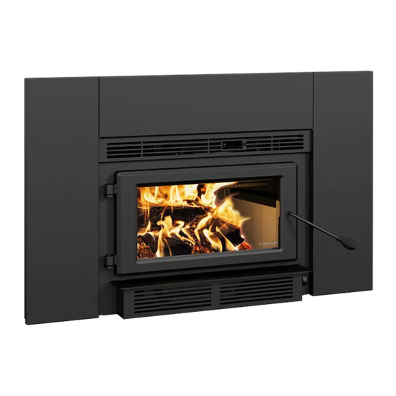
Wood Insert
Owner's Manual
Part 1 of 2
SAFETY NOTIFICATIONS
AND GENERAL INFORMATION
CONTACT LOCAL BUILDING OR FIRE OFFICIALS ABOUT RESTRICTIONS AND INSTALLATION INSPECTION REQUIREMENTS IN
THE AREA.
READ THIS ENTIRE GUIDE BEFORE INSTALLATION AND USE OF THIS WOOD INSERT. FAILURE TO FOLLOW THESE
INSTRUCTIONS COULD RESULT IN PROPERTY DAMAGE, BODILY INJURY OR EVEN DEATH.
READ AND KEEP THIS GUIDE FOR REFERENCE
Printed in Canada
46235A
Advertisement
Chapters
Table of Contents

Related Manuals for Century Heating CW2100


Summary of Contents for Century Heating CW2100
- Page 1 Wood Insert Owner’s Manual Part 1 of 2 SAFETY NOTIFICATIONS AND GENERAL INFORMATION CONTACT LOCAL BUILDING OR FIRE OFFICIALS ABOUT RESTRICTIONS AND INSTALLATION INSPECTION REQUIREMENTS IN THE AREA. READ THIS ENTIRE GUIDE BEFORE INSTALLATION AND USE OF THIS WOOD INSERT. FAILURE TO FOLLOW THESE INSTRUCTIONS COULD RESULT IN PROPERTY DAMAGE, BODILY INJURY OR EVEN DEATH.
- Page 3 THANK YOU FOR CHOOSING THIS WOOD INSERT. As one of North America’s Contact local building or fire largest and most respected officials about restrictions wood stove and fireplace and installation inspection If this insert is not manufacturers, Stove Builder requirements in the area. installed properly, International takes pride in the combustible materials...
-
Page 5: Table Of Contents
TABLE OF CONTENTS 1. Safety Information and Environment ..................6 Regulations Covering Insert Installation ................ 7 Certification Label ....................... 7 Emissions and Efficiency ..................... 8 Materials ........................8 2. Fuel ............................9 Tree Species ....................... 9 Log Length ......................... 9 Piece Size .........................10 Compressed Wood Logs ....................10 Drying Time .......................10... -
Page 6: Safety Information And Environment
1. Safety Information and Environment • Some appliances have been tested for use with an open door in conjunction with a fire screen, sold separately (See in the Wood Insert Installation and Operation Manual if your appliance has this option). The door may be opened, or fire screen removed only during lighting procedures or reloading. -
Page 7: Regulations Covering Insert Installation
• The information given on the certification label affixed to the appliance always overrides the information published, in any other media (owner’s manual, catalogues, flyers, magazines and web sites). • Mixing of appliance components from different sources or modifying components may result in hazardous conditions. -
Page 8: Emissions And Efficiency
the event replacement parts or technical assistance is required. Emissions and Efficiency The low smoke emissions produced by the special features inside this insert firebox means that the household will release up to 90% less smoke into the outside environment than if an older conventional insert was used. -
Page 9: Fuel
2. Fuel Good firewood has been cut to the correct length for the insert, split to a range of sizes and stacked in an open area until its moisture content is down to 15% to 20%. DO NOT BURN: • COAL; •... -
Page 10: Piece Size
Piece Size Firewood dries more quickly when it is split. Large unsplit rounds can take years to dry enough to burn. Even when dried, unsplit logs are difficult to ignite because they don’t have the sharp edges where the flames first catch. Wood should be split to a range of sizes, from about 3 to 6 (75 mm to 150 mm) in cross section. -
Page 11: Burning Wood Efficiently
Use these guidelines to find out if the firewood is dry enough to burn: − Cracks form at the ends of logs as they dry; − The wood turns from white or cream colored to grey or yellow; − Two pieces of wood struck together sounds hollow; −... -
Page 12: Zone Heating
3.2.2 The Top Down Method This method is the opposite of the conventional method and only works properly if well-seasoned wood is used. Place three or four small, split, dry logs in the firebox. Arrange the kindling wood on the logs in two layers at right angles and place a dozen finely split kindling on the second row. -
Page 13: Combustion Cycles
Although the insert may be able to heat the main living areas of the house to an adequate temperature, it is strongly recommended to also have a conventional oil, gas or electric heating system to provide backup heating. The success of zone heating will depend on several factors, including the correct sizing and location of the insert, the size, layout and age of the home and the climate zone. -
Page 14: Rekindling A Fire
Rekindling a Fire When the temperature of the room is lower and all that remains is embers, it is time to reload. Remove excess ash from the front of the firebox and bring the ashes forward. Place a new load of wood on, and at the back of the embers. -
Page 15: Air Intake Control
Air Intake Control Once the firewood, firebox and chimney are hot, air intake can be reduced to achieve a steady burn. As the air intake is reduced, the burn rate decreases. The images shown are for guidance only This has the effect of distributing the thermal energy of and may differ from your product, but the operation remains the same. - Page 16 3.8.2 Low and Long Output Fires For a fire that will last up to eight hours but will not produce intense heat, use soft wood and place the logs compactly in the firebox. Before reducing the air intake, the load will have to burn at full heat for long enough for charring the surface of the logs.
-
Page 17: Maintenance
East-west loads allow a limited amount of wood since too many logs could cause them to fall on the glass. East-west loads, placed in a compact way, take a long time before breaking down. They are excellent for low-intensity, long-lasting fires in relatively mild weather. 3.8.6 Carbon Monoxide When there is no more flame in the firebox and there are still some unburned logs, check outside... -
Page 18: Operating The Insert
The deposits that form on the glass are the best indication of the fuel quality and success in properly using the insert. These stains can be cleaned with a special wood insert glass cleaner. Do not use abrasive products to clean the glass. The goal should be having a clear glass with no brown stains. -
Page 19: Fire Screen
The blower has a variable speed rheostat that can be adjusted from high (HI) to low (LO) and closed (OFF). Allow the insert to reach operating temperature (approximately one hour) before turning on the blower, since increased airflow from the blower will remove heat and affect the start up combustion efficiency. -
Page 20: Masonry Fireplace Requirements
Establish a routine for the fuel, wood insert and firing technique. Check daily for creosote build-up until experience shows how often you need to clean to be safe. Be aware that the hotter the fire, the less creosote is deposited and weekly cleaning may be necessary in mild weather even though monthly cleaning may be enough in the coldest months. -
Page 21: Chimney Caps
Removal of any parts, which render the fireplace unfit for use with solid fuel, requires the fireplace to be permanently labelled by the installer as being no longer suitable for solid fuel, until the removed parts are replaced and the fireplace is restored to its original certified condition. Also, any air vents, grilles, or louvers that allow air circulation around the fireplace must not be removed or blocked. -
Page 22: Suitable Chimneys
In Canada, the CSA-B365 Standard permits «Roxul» type wool to be stuffed around the liner as it passes through the throat area as an alternative to a sheet metal block-off plate. However, this method is less efficient than using a plate. Figure 4 : Block-off Plate Figure 5 : Block-off Plate Suitable Chimneys... -
Page 23: Liner Connection
Liner Connection Two options are possible to connect the liner to the insert: 7.5.1 Liner Starter Adaptor Install the chimney liner starter adapter, provided with the chimney liner. Follow the chimney liner starter adapter manufacturer’s instructions. In order to connect the chimney liner starter adapter to the flue outlet, install three brackets with the three screws, all provided in the user manuals kit, on top of the insert. -
Page 24: Minimum Chimney Height
Minimum Chimney Height The top of the chimney should be tall enough to be above the air turbulence caused when wind blows against the house and its roof. The chimney must extend at least 3 ft. (1 m) above the highest point of contact with the roof, and at least 2 ft. -
Page 25: Supply Of Combustion Air
Supply of Combustion Air In Canada, wood inserts are not required to have a combustion air supply from outside. Research has shown that outside air supply do not compensate for the depressurization of the house and may not be sufficient to provide a supply of combustion air in windy weather. However, to reduce the risks against smoke spillage due to house depressurization, a carbon monoxide (CO) detector is required in the room where the insert is installed. - Page 26 This document is available for free download on the Stove Builder International inc. manufacturer’s website. It is a copyrighted document. 250, rue de Copenhague, Resale is strictly prohibited. The manufacturer may update St-Augustin-de-Desmaures (Québec) Canada this document from time to time and cannot be responsible G3A 2H3 for problems, injuries, or damages arising out of the use 1-877-356-6663...
- Page 27 Wood Insert Owner's Manual Part 2 of 2 INSTALLATION AND OPERATION REQUIREMENTS CW2100 INSERT (CB00027 Model) Safety tested according to ULC S628, UL 1482 and UL 737 by an accredited laboratory. US Environmental Protection Agency phase II certified wood insert compliant with 2020 cord wood standard.
- Page 28 ONLINE WARRANTY REGISTRATION If the unit requires repairs during the warranty period, proof of purchase must be provided. The purchase invoice must be kept. The date indicated on it establishes the warranty period. If it can not be provided, the warranty period will be determined by the date of manufacture of the product. It is also highly recommended to register the warranty online at https://www.century-heating.com/ca/en/warranty/warranty-registration Registering the warranty will help to quickly find the information needed on the unit.
- Page 29 CERTIFICATION PLATE...
- Page 30 Product Specification Manual - CW2100 Page 4...
- Page 31 Faceplate Decorative Panel Installation/Removal ............26 Optional Fresh Air Intake Kit Installation...............27 3.10 Optional Fire Screen Installation ..................28 3.11 Air Tubes and Baffle Installation ..................29 3.12 Removal Instructions ....................32 3.13 Exploded Diagram and Parts List ................33 Product Specification Manual - CW2100 Page 5...
-
Page 32: General Information
This appliance is officially tested and certified by an independent agency. Tested and certified in compliance with CFR 40 part 60, subpart AAA, section 60.534(a)(1(ii) and ASTM E3053-17 based on the ALT-125 send by EPA on February 28 , 2018. Carbon monoxide. Product Specification Manual - CW2100 Page 6... -
Page 33: Specifications
CAN/CSAZ240 MH standard. Tested and certified in compliance with CFR 40 part 60, subpart AAA, section 60.534(a)(1(ii) and ASTM E3053-17 based on the ALT-125 send by EPA on February 28 , 2018. Product Specification Manual - CW2100 Page 7... -
Page 34: Dimensions
Dimensions Product Specification Manual - CW2100 Page 8... - Page 35 8 3/4" 224mm Product Specification Manual - CW2100 Page 9...
-
Page 36: Epa Loading
OFF to avoid blowing ash outside the combustion chamber. Refer to section "5.1 Blower" of the owner's manual for how to turn OFF the fan. Product Specification Manual - CW2100 Page 10... -
Page 37: Clearances To Combustible Material
1" (25 mm) 15 ½" (394 mm) surround If a fresh air intake is required, it is recommended to add at least 4" to the width of the minimum opening of the hearth. Product Specification Manual - CW2100 Page 11... -
Page 38: Floor Protection
(0 mm) D=B- G (257 mm) extension facing From door opening. The depth of the hearth extension in front of the insert is included in the calculation of the floor protector’s dimensions. Product Specification Manual - CW2100 Page 12... -
Page 39: R Value
Required floor protection R of 1.00. Proposed materials: four inches of brick and one inch of Durock® board: Information as reported by manufacturers and other resources. Horizontal still air can’t be «stack» to accumulate R-values; each layer must be separated with another non-combustible material. Product Specification Manual - CW2100 Page 13... - Page 40 K values to R by dividing the thickness of each material by its K value. Add R values of the proposed materials as shown in the previous example. Exemple: K value = 0.75 Thickness = 1 R value = Thickness/K = 1/0.75 = 1.33 Product Specification Manual - CW2100 Page 14...
-
Page 41: Installing Options On Your Product And Replacing Parts
(10 mm) long of the gasket when cutting and press the end into the groove. Tuck any loose fibers under the gasket and into the silicone. Close the door. Do not use the insert for 24 hours. Product Specification Manual - CW2100 Page 15... - Page 42 Using a flat screwdriver, turn the adjustable hinge rods in the direction shown to adjust the doors. Tighten all door hinge pressure screws when they are at the desired positions. Configurations 1-2-3-4-5-6, show in which direction these act on the adjustment of the door. Product Specification Manual - CW2100 Page 16...
-
Page 43: Mandatory Installation
(B) and gain access to the wires. Save the screws for later. 2. Disconnect the black (C) and white (D) wires. 3. Remove the ground screw (E) to remove the green wire. Save the screw for later. Product Specification Manual - CW2100 Page 17... - Page 44 5. Remove the piece of metal (G) from the plate (B) obstructing the hole to the left of the power cord (H) using pliers or a screwdriver. Cut the power cord (H) on each side of the black clamp. Product Specification Manual - CW2100 Page 18...
- Page 45 9. Close the connection box by screwing in the plate (B) with the two screws (A) kept in step 1 and secure the BX wire by tightening the screw (L) of the connector (I). Product Specification Manual - CW2100 Page 19...
-
Page 46: Changing The Side Of The Blower Power Cord
Remove the four screws (F) that hold the connection box (G) to the insert and gently pull it out until the white and black wires come out of the insert. Keep the screws. Product Specification Manual - CW2100 Page 20... - Page 47 Then pass the wires through the grommet (J) located on the side at the front of the device. 5. Screw the connection box (G) with the four screws (F) kept in step 2. Product Specification Manual - CW2100 Page 21...
- Page 48 (extension supplied with the manual kit). 8. Secure the excess wires using the three plastic grommets (C) removed in step 1. 9. Reinstall the grille (B) with the screws (A) kept in step 1. Product Specification Manual - CW2100 Page 22...
-
Page 49: Blower Removal
Remove the two screws (A) on each side of 2. Unscrew the two wing nuts (C) on each the grille (B) to be able to remove it. side of the fan. 3. Take out the fan (D). Product Specification Manual - CW2100 Page 23... -
Page 50: Removable Air Control Handle
This insert comes with a removable handle for the primary air control. A holder for the handle is supplied with the manual. Here is an example of the holder installation. CAUTION: Do not leave the handle on the air control after use, as it will get very hot. Product Specification Manual - CW2100 Page 24... -
Page 51: Faceplate Installation
(B) and (C). Secure together using the bolts (D) and nuts (E) provided. Install the grille on the assembled faceplate and bend the tabs using pliers. Hang the assembled faceplate on the insert. Product Specification Manual - CW2100 Page 25... -
Page 52: Faceplate Decorative Panel Installation/Removal
Faceplate decorative panel removal • Remove the screws (B) at each end of the panel (A) to be able to remove it afterwards. Faceplate decorative panel installation • Screw the panel with 6 additional screws (B). Product Specification Manual - CW2100 Page 26... -
Page 53: Optional Fresh Air Intake Kit Installation
(J) using the other pipe clamp. The outside wall termination must be installed outside of the home. The pipe must be HVAC type, insulated, and must comply with ULC S110 and/or UL 181, Class 0 or Class 1. Product Specification Manual - CW2100 Page 27... -
Page 54: Optional Fire Screen Installation
In the United States or in provinces with a particulate emissions limit (e.g.: US EPA), the use of open-door wood stoves with a rigid firescreen is prohibited. Open the door. Hold the fire screen by the two handles and bring it close to the door opening. Product Specification Manual - CW2100 Page 28... -
Page 55: Air Tubes And Baffle Installation
Starting with the rear tube, lean and insert the right end of the secondary air tube into the rear right channel hole. Then lift and insert the left end of the tube into the rear left channel. Product Specification Manual - CW2100 Page 29... - Page 56 Align the notch in the left end of the tube with the key of the left air channel hole. Using a « Wise grip » hold the tube and lock it in place by turning the tube as shown. Make sure the notch reaches the end of the key way.
-
Page 58: Removal Instructions
3.12 Removal Instructions For inspecting purposes, the insert may need to be removed. To remove the insert, follow these instructions: • Remove the blower grille (E) and faceplate (D) by lifting it and then pulling on it. • Remove the blower (C). •... -
Page 59: Exploded Diagram And Parts List
3.13 Exploded Diagram and Parts List Product Specification Manual - CW2100 Page 33... - Page 60 BLACK SCREW #10 X 5/8" QUADREX #2 TYPE A SE74166 HANDLE 30898 REPLACEMENT KIT SE74766 DAMPER ASSEMBLY PL34052 LINER FIXATION BRACKET 44075 TANGENTIAL BLOWER 1800 115V-60hZ-30W (S) 90 CFM SE74782 DOOR ASSEMBLY PL74846 ASH TRAY PL74845 FRONT HOUSING Product Specification Manual - CW2100 Page 34...
- Page 61 Before shipping your unit or defective component to our plant, you must obtain an Authorization Number from your CENTURY. Any merchandise shipped to our plant without authorization will be refused automatically and returned to sender. Product Specification Manual - CW2100 Page 35...
- Page 62 This document is available for free download on the Stove Builder International inc. manufacturer’s website. It is a copyrighted document. 250, rue de Copenhague, Resale is strictly prohibited. The manufacturer may update St-Augustin-de-Desmaures (Québec) Canada this document from time to time and cannot be responsible G3A 2H3 for problems, injuries, or damages arising out of the use 1-877-356-6663...
Need help?
Do you have a question about the CW2100 and is the answer not in the manual?
Questions and answers