
Related Manuals for ITT Engineered Valves 903


Summary of Contents for ITT Engineered Valves 903
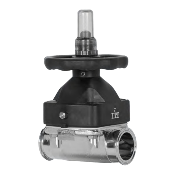
- Page 1 Installation, Operation, and Maintenance Manual Handwheel Operated Valves (903, 913, 963)
-
Page 3: Table Of Contents
Table of Contents Table of Contents 1 Introduction and Safety ............................ 2 1.1 Safety message levels ..........................2 1.2 User health and safety ..........................2 2 Transportation and storage ..........................5 2.1 Handling and unpacking guidelines......................5 2.2 Storage, disposal, and return requirements ....................5 3 Product Description ............................ -
Page 4: Introduction And Safety
1.2 User health and safety General precautions This product is designed and manufactured using good workmanship and materials, and meets all appli- cable industry standards. This product should be used only as recommended by ITT. WARNING: • Misapplication of the valve can result in injury or property damage. Select valves and valve components of the proper materials and make sure that they are consistent with your specific performance requirements. - Page 5 • Ensure that the contents of the operating instructions have been fully understood by the personnel. Instruction and training can be carried out by either ITT or the reseller of the valve by order of the operat- ing company WARNING: California Proposition 65 Cancer http://www.P65Warnings.ca.gov.
- Page 6 1.2 User health and safety Do not use "cheater bars" to operate manual valves. Damage to the valve or personal injury could result. Handwheel Operated Valves (903, 913, 963) Installation, Operation, and Maintenance Manual...
-
Page 7: Transportation And Storage
Dispose of this product and associated components in compliance with federal, state, and local regula- tions. Return Ensure these requirements are met before you return a product to ITT: • Contact ITT for specific instructions on how to return the product. -
Page 8: Product Description
3 Product Description 3 Product Description 3.1 Topworks identification Model number Code Description Cast iron bonnet with rising stem and travel stop 903S Cast iron sealed bonnet with rising stem and travel stop Stainless steel bonnet with rising stem and travel stop 913S Stainless steel sealed bonnet with rising stem and travel stop PAS plastic bonnet with rising handwheel and travel stop... - Page 9 3.3 Valve diaphragm identification Date code Supplier code Figure 2: Elastomer diaphragm front Valve size Grade of diaphragm Figure 3: Elastomer diaphragm back Material code Date code Figure 4: PTFE diaphragm Handwheel Operated Valves (903, 913, 963) Installation, Operation, and Maintenance Manual...
-
Page 10: Installation
4 Installation 4 Installation 4.1 Install the valve and topworks NOTICE: The topworks size and configuration can limit the actual operating pressure. Consult the Pure- Flo catalog for pressure limitations. Consult the factory or engineering catalog for vacuum op- eration. If you have a weld end valve, then consider the following: If you are welding ... -
Page 11: Fastener Torque Table For Valve Body To Topworks
4.2 Tighten the bonnet fasteners Tighten the bonnet fasteners in a crisscross pattern. For more information, see 4.2.1 Fastener torque table for valve body to topworks on page Make multiple crisscross passes to build up torque to the final table value. Make additional criss- cross passes using final table values to evenly tighten each fastener to within 5% of torque value. -
Page 12: Set The Travel Stop
4.3 Set the travel stop Values given are for lubricated fasteners. Minimum values given will provide longer diaphragm cycle life for valves in non-auto- clave and low thermal cycle conditions. Maximum values given will be required for autoclave conditions and for high thermal cycle conditions. -
Page 13: Operation
For a sealed bonnet, the bonnet intervals and seals should be constructed of materials suitable for exposure to the process fluid or gas. If in doubt, contact ITT for evaluation. The valve is closed with a clockwise rotation of the handwheel. - Page 14 5.2 Operate the Adjustable Open Stop Turn handwheel until it is in the desired open position. Turn capscrew clockwise until its lower end is in contact with the top of the stem of the bonnet as- sembly. Turn the nut clockwise tight against the top of the cap. Opening stop is now set.
-
Page 15: Maintenance
Action if problem is found External valve parts Excessive wear or corrosion • Replace the affected parts • Contact ITT to obtain replace- ment parts or for specific in- structions Non sealed bonnet Fluid weeping from the weep hole Replace the valve diaphragm... -
Page 16: Disassemble The Valve
6.4 Disassemble the valve 6.4 Disassemble the valve Remove all line pressure. Turn the valve to the open position counter clockwise at least one turn. Remove the bonnet fasteners. Lift the topworks assembly from the valve body. 6.5 Replace the valve diaphragm Disassemble the valve. - Page 17 6.5 Replace the valve diaphragm Rotate the diaphragm until hard stop or heavy resistance is achieved and additional force does not significantly rotate the diaphragm into the compressor. If replacing a PTFE diaphragm, re-invert the diaphragm. Back off (no more than half turn) until the bolt holes in diaphragm and the bonnet flange align. Rotate the handwheel counterclockwise just enough to permit the flange area of the diaphragm to rest flat against the flange area of the bonnet.
-
Page 18: Change The Diaphragm Type
6.6 Change the diaphragm type 6.6 Change the diaphragm type Remove the bonnet nuts and lift off the bonnet. Remove the plastic cap and travel stop nut. Loosen the handwheel setscrew(s) and remove the handwheel from the bonnet. Remove the diaphragm, spindle and bushing assembly by withdrawing it through bottom of bonnet. Remove the compressor. - Page 19 6.7 Replace the o-rings Unscrew the diaphragm and spindle assembly from the handwheel bushing. Remove o-rings: Valve size (in) Valve size (DN) Action .5–2 15–50 Remove o-ring 2 from the groove in spindle outside diame- ter. 2.5–6 80–150 Remove o-rings 2 and 4 from the spindle plug.
- Page 20 6.7 Replace the o-rings Select the proper o-ring for the valve size. Valve size, inches (DN) O-ring 3 0.50 (15) #118 0.75 (20) #119 1.00 (25) #121 1.25 (32) #122 1.50 (40) #122 2.00 (50) #122 2.50 (65) #128 3.00 (80) #128 4.00 (100) #130...
-
Page 21: Parts Listing And Cross-Sectional Drawings
7 Parts Listing and Cross-Sectional Drawings 7 Parts Listing and Cross-Sectional Drawings 7.1 963 PAS plastic bonnet List of parts Figure 7: Figure 9: V-notch vent plug for sealed bonnet Figure 8: Bonnet and bolting detail for fabrications with studs Item Description Material... - Page 22 7.1 963 PAS plastic bonnet Item Description Material Quantity Wiper seal Viton Polyolefin foam O-ring Viton Screw Stainless steel 1 or 2 O-ring Viton O-ring Viton Thrust bearing Polyethylene As required Bushing Brass Compressor Bronze or stainless steel Spirol pin Silicone Tube nut Brass...
- Page 23 Visit our website for the latest version of this document and more information: www.engvalves.com ITT Engineered Valves 33 Centerville Road Lancaster, PA 17603 Form IOM.HWO.en-US.2022-11 ©2022 ITT Inc. or its wholly-owned subsidiaries The original instruction is in English. All non-English instructions are translations of the original instruction.
Need help?
Do you have a question about the Engineered Valves 903 and is the answer not in the manual?
Questions and answers