Table of Contents
Advertisement
Quick Links
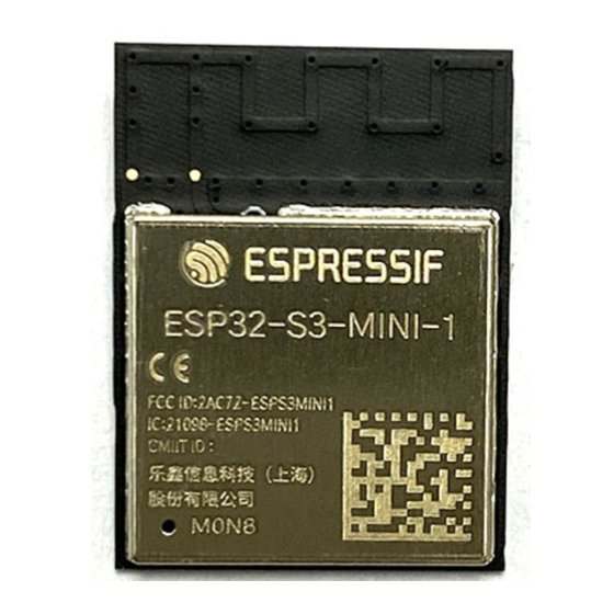
ESP32-S3-MINI-1
ESP32-S3-MINI-1U
User Manual
Small-sized module supporting 2.4 GHz Wi-Fi (802.11 b/g/n) and Bluetooth
Built around ESP32-S3 series of SoCs, Xtensa
8 MB flash
39 GPIOs, rich set of peripherals
On-board PCB antenna or external antenna connector
ESP32-S3-MINI-1
www.espressif.com
®
dual-core 32-bit LX7 microprocessor
ESP32-S3-MINI-1U
®
5 (LE)
Pre-release v0.6
Espressif Systems
Copyright © 2022
Advertisement
Table of Contents

Related Manuals for Espressif Systems ESP32-S3-MINI-1


Summary of Contents for Espressif Systems ESP32-S3-MINI-1
- Page 1 ESP32-S3-MINI-1 ESP32-S3-MINI-1U User Manual ® Small-sized module supporting 2.4 GHz Wi-Fi (802.11 b/g/n) and Bluetooth 5 (LE) ® Built around ESP32-S3 series of SoCs, Xtensa dual-core 32-bit LX7 microprocessor 8 MB flash 39 GPIOs, rich set of peripherals On-board PCB antenna or external antenna connector...
-
Page 2: Features
85 °C 1.2 Description ESP32-S3-MINI-1 and ESP32-S3-MINI-1U are two powerful, generic Wi-Fi + Bluetooth LE MCU modules that feature a rich set of peripherals, yet an optimized size. They are an ideal choice for a wide variety of application scenarios related to Internet of Things (IoT), such as embedded systems, smart home, wearable electronics, etc. - Page 3 45 GPIOs. It also includes a full-speed USB 1.1 On-The-Go (OTG) interface to enable USB communication. Note: * For more information on ESP32-S3FN8, please refer to ESP32-S3 Series Datasheet Espressif Systems ESP32-S3-MINI-1 & MINI-1U User Manual v0.6 Submit Documentation Feedback...
-
Page 4: Table Of Contents
3.4.2 Connect Your Device 3.4.3 Configure 3.4.4 Build the Project 3.4.5 Flash onto the Device 3.4.6 Monitor U.S. FCC Statement Industry Canada Statement Related Documentation and Resources Revision History Espressif Systems ESP32-S3-MINI-1 & MINI-1U User Manual v0.6 Submit Documentation Feedback... -
Page 5: Pin Definitions
2 Pin Definitions 2.1 Pin Layout The pin diagram below shows the approximate location of pins on the module. The pin diagram is applicable for ESP32-S3-MINI-1 and ESP32-S3-MINI-1U, but the latter has no keepout zone. Keepout Zone Pin 62 Pin 65... - Page 6 SPIDQS, GPIO37, FSPIQ, SUBSPIQ IO38 I/O/T GPIO38, FSPIWP, SUBSPIWP IO39 I/O/T MTCK, GPIO39, CLK_OUT3, SUBSPICS1 IO40 I/O/T MTDO, GPIO40, CLK_OUT2 IO41 I/O/T MTDI, GPIO41, CLK_OUT1 Cont’d on next page Espressif Systems ESP32-S3-MINI-1 & MINI-1U User Manual v0.6 Submit Documentation Feedback...
- Page 7 P: power supply; I: input; O: output; T: high impedance. Pin functions in bold font are the default pin functions. For pin 28 ∼ 29, 31 ∼ 33, the default function is decided by eFuse bit. Espressif Systems ESP32-S3-MINI-1 & MINI-1U User Manual v0.6 Submit Documentation Feedback...
-
Page 8: Get Started
Guide. 3.2 Hardware Connection 1. Solder the ESP32-S3-MINI-1 or ESP32-S3-MINI-1U module to the RF testing board as shown in Figure 2. Figure 2: Hardware Connection 2. Connect the RF testing board to the USB-to-Serial board via TXD, RXD, and GND. -
Page 9: Set Up Development Environment
IO0 is internally logic high. If IO0 is set to pull-up, the Boot mode is selected. If this pin is pull-down or left floating, the Download mode is selected. For more information on ESP32-S3-MINI-1 or ESP32-S3-MINI-1U, please refer to ESP32-S3 Series Datasheet 3.3 Set up Development Environment... -
Page 10: Set Up Tools
Now everything is ready, you can build your first project on ESP32-S3-MINI-1 or ESP32-S3-MINI-1U module. 3.4 Create Your First Project 3.4.1 Start a Project Now you are ready to prepare your application for ESP32-S3-MINI-1 or ESP32-S3-MINI-1U module. You can start with get-started/hello_world project from examples directory in ESP-IDF. -
Page 11: Configure
The colors of the menu could be different in your terminal. You can change the appearance with the option ‘--style’. Please run ‘idf.py menuconfig --help’ for further information. 3.4.4 Build the Project Build the project by running: idf.py build Espressif Systems ESP32-S3-MINI-1 & MINI-1U User Manual v0.6 Submit Documentation Feedback... -
Page 12: Flash Onto The Device
When flashing, you will see the output log similar to the following: esptool.py esp32s3 -p /dev/ttyUSB0 -b 460800 --before=default_reset --after=hard_reset write_flash --flash_mode dio --flash_freq 80m --flash_size 2MB 0x0 bootloader/bootloader. 0x10000 hello_world.bin 0x8000 partition_table/partition-table.bin esptool.py v3.2-dev Serial port /dev/ttyUSB0 Connecting..Espressif Systems ESP32-S3-MINI-1 & MINI-1U User Manual v0.6 Submit Documentation Feedback... -
Page 13: Monitor
To check if “hello_world” is indeed running, type ‘idf.py -p PORT monitor‘ (Do not forget to replace PORT with your serial port name). This command launches the IDF Monitor application: $ idf.py -p /dev/ttyUSB0 monitor Running idf_monitor in directory [...]/esp/hello_world/build Executing ”python [...]/esp-idf/tools/idf_monitor.py -b 115200 [...]/esp/hello_world/build/hello-world.elf”... Espressif Systems ESP32-S3-MINI-1 & MINI-1U User Manual v0.6 Submit Documentation Feedback... - Page 14 Restarting in 8 seconds... Restarting in 7 seconds... To exit IDF monitor use the shortcut Ctrl+]. That’s all what you need to get started with ESP32-S3-MINI-1 or ESP32-S3-MINI-1U module! Now you are ready to try some other examples in ESP-IDF, or go right to developing your own applications.
-
Page 15: S. Fcc Statement
The modules must be installed in the host equipment such that at least 20cm is maintained between the antenna and users’ body; and if RF exposure statement or module layout is changed, then the host product manufacturer Espressif Systems ESP32-S3-MINI-1 & MINI-1U User Manual v0.6 Submit Documentation Feedback... - Page 16 Only when all the test results of test modes comply with FCC requirements, then the end product can be sold legally. Espressif Systems ESP32-S3-MINI-1 & MINI-1U User Manual v0.6 Submit Documentation Feedback...
- Page 17 • The transmitter module may not be co-located with any other transmitter or antenna. • The modules shall be only used with the external antenna(s) that has been originally tested and certified with the modules. Espressif Systems ESP32-S3-MINI-1 & MINI-1U User Manual v0.6 Submit Documentation Feedback...
- Page 18 FCC authorization. End Product Labeling The final end product must be labeled in a visible area with the following: “Contains Transmitter Module FCC ID: 2AC7Z-ESPS3MINI1”. Espressif Systems ESP32-S3-MINI-1 & MINI-1U User Manual v0.6 Submit Documentation Feedback...
-
Page 19: Industry Canada Statement
As long as 2 conditions above are met, further transmitter test will not be required. However, the OEM integrator is still responsible for testing their end-product for any additional compliance requirements required with this module installed. Espressif Systems ESP32-S3-MINI-1 & MINI-1U User Manual v0.6 Submit Documentation Feedback... - Page 20 L’intégrateur OEM doit être conscient de ne pas fournir des informations à l’utilisateur final quant à la façon d’installer ou de supprimer ce module RF dans le manuel de l’utilisateur du produit final qui intègre ce module. Le Espressif Systems ESP32-S3-MINI-1 & MINI-1U User Manual v0.6 Submit Documentation Feedback...
- Page 21 5 Industry Canada Statement manuel de l’utilisateur final doit inclure toutes les informations réglementaires requises et avertissements comme indiqué dans ce manuel. Espressif Systems ESP32-S3-MINI-1 & MINI-1U User Manual v0.6 Submit Documentation Feedback...
-
Page 22: Related Documentation And Resources
Find an Espressif hardware product suitable for your needs by comparing or applying filters. http://products.espressif.com/#/product-selector?language=en Contact Us • See the tabs Sales Questions, Technical Enquiries, Circuit Schematic & PCB Design Review, Get Samples (Online stores), Become Our Supplier, Comments & Suggestions. http://espressif.com/en/contact-us/sales-questions Espressif Systems ESP32-S3-MINI-1 & MINI-1U User Manual v0.6 Submit Documentation Feedback... -
Page 23: Revision History
Revision History Revision History Date Version Release notes 2022-02-24 v0.6 Overall update for chip revision 1 2021-03-30 v0.1 Preliminary release, for chip revision 0 Espressif Systems ESP32-S3-MINI-1 & MINI-1U User Manual v0.6 Submit Documentation Feedback... - Page 24 The Wi-Fi Alliance Member logo is a trademark of the Wi-Fi Alliance. The Bluetooth logo is a registered trademark of Bluetooth SIG. All trade names, trademarks and registered trademarks mentioned in this document are property www.espressif.com of their respective owners, and are hereby acknowledged. Copyright © 2022 Espressif Systems (Shanghai) Co., Ltd. All rights reserved.
Need help?
Do you have a question about the ESP32-S3-MINI-1 and is the answer not in the manual?
Questions and answers