Advertisement
Quick Links
Advertisement

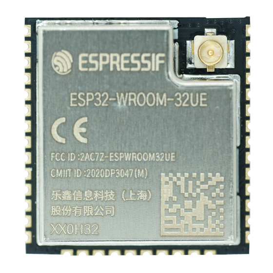
Summary of Contents for Espressif Systems ESP32-WROOM-32UE
- Page 1 ESP32-WROOM-32UE User Manual Version 0.1 Espressif Systems Copyright © 2019 www.espressif.com...
- Page 2 About This Document This document provides the specifications for the ESP32-WROOM-32UE modules with PCB antenna and IPEX an-tenna. Revision History For revision history of this document, please refer to the last page. Documentation Change Notification Espressif provides email notifications to keep customers updated on changes to technical documentation.
- Page 3 4 MB (3.10 ± 0.10) mm (including metallic shield) Notes: 1. ESP32-WROOM-32UE (IPEX) with 8 MB flash or 16 MB flash is available for custom order. 2. For detailed ordering information, please see Espressif Product Ordering Information. 3. For dimensions of the IPEX connector, please see Chapter 10.
- Page 4 3.6 V Minimum current delivered by 500 mA power supply Recommended operating tem- –40 °C 85 °C perature range Package size (18.00±0.10) mm × (31.40±0.10) mm × (3.30±0.10) mm Moisture sensitivity level (MSL) Level 3 ESP32-WROOM-32UE User Manual Espressif Systems V0.1...
- Page 5 2. Pin Definitions Pin Definitions 2.1 Pin Layout Figure 1: Pin Layout of ESP32-WROOM-32UE (Top View) ESP32-WROOM-32UE User Manual V0.1 Espressif Systems...
- Page 6 2. Pin Definitions 2.2 Pin Description ESP32-WROOM-32UE has 38 pins. See pin definitions in Table 3. Table 3: Pin Definitions Name Type Function Ground Power supply Module-enable signal. Active high. SENSOR_VP 4 GPIO36, ADC1_CH0, RTC_GPIO0 SENSOR_VN 5 GPIO39, ADC1_CH3, RTC_GPIO3...
- Page 7 After reset release, the strapping pins work as normal-function pins. Refer to Table for a detailed boot-mode configuration by strapping pins. Table 4: Strapping Pins Voltage of Internal LDO (VDD_SDIO) Default 3.3 V 1.8 V MTDI Pull-down ESP32-WROOM-32UE User Manual V0.1 Espressif Systems...
- Page 8 ”Timing of SDIO Slave” after booting. • Internal pull-up resistor (R9) for MTDI is not populated in the module, as the flash and SRAM in ESP32- WROOM-32UE only support a power voltage of 3.3 V (output by VDD_SDIO) ESP32-WROOM-32UE User Manual V0.1 Espressif Systems...
- Page 9 3. Functional Description 3. Functional Description This chapter describes the modules and functions integrated in ESP32-WROOM-32UE. 3.1 CPU and Internal Memory ® ESP32-D0WD-V3 contains two low-power Xtensa 32-bit LX6 microprocessors. The internal memory includes: • 448 KB of ROM for booting and core functions.
- Page 10 With the use of advanced power-management technologies, ESP32 can switch between different power modes. For details on ESP32’s power consumption in different power modes, please refer to section ”RTC and Low- ESP32 User Manual. Power Management” in ESP32-WROOM-32UE User Manual Espressif Systems V0.1...
- Page 11 External connections can be made to any GPIO except for GPIOs in the range 6-11, 16, or 17. GPIOs 6-11 are connected to the module’s integrated SPI flash. For details, please see Section Schematics. ESP32-WROOM-32UE User Manual Espressif Systems V0.1...
- Page 12 Low-level output voltage 1; 2 VDD3P3_CPU power domain High-level source current 1; 2 (VDD = 3.3 V, V >= 2.64 V, VDD3P3_RTC power domain output drive strength set to the 1; 3 VDD_SDIO power domain maximum) ESP32-WROOM-32UE User Manual V0.1 Espressif Systems...
- Page 13 2. For the modules that use IPEX antennas, the output impedance is 50 Ω. For other modules without IPEX antennas, users do not need to concern about the output impedance. 3. Target TX power is configurable based on device or certification requirements. ESP32-WROOM-32UE User Manual V0.1 Espressif Systems...
- Page 14 Adjacent channel transmit power F = F0 ± 3 MHz –58 F = F0 ± > 3 MHz –60 ∆ f1 ∆ f2 ∆ f2 /∆ f1 –0.92 ICFT –10 Drift rate kHz/50 s Drift ESP32-WROOM-32UE User Manual Espressif Systems V0.1...
- Page 15 7LPH60 ~ 90s; Peak Temp.: 235 ~ 250 (<245 recommended) Time: 30 ~ 70s Cooling zone — Peak Temp. ~ 180 Ramp-down rate: -1 ~ -5 /s Solder — Sn&Ag&Cu Lead-free solder (SAC305) Figure 2: Reflow Profile ESP32-WROOM-32UE User Manual Espressif Systems V0.1...
- Page 16 Revision History Revision History Date Version Release notes Preliminary release for certification CE. 2020.02 V0.1 OEM Guidance 1. Applicable FCC rules This module is granted by Single Modular Approval. It complies to the requirements of FCC part 15C, section 15.247 rules. 2.
- Page 17 6. Antenna Antenna type: Dipole antenna with IPEX connector; Peak gain: 2.33dBi 7. Label and compliance information An exterior label on OEM’s end product can use wording such as the following: “Contains Transmitter Module FCC ID: 2AC7Z-ESPWROOM32UE” or “Contains FCC ID: 2AC7Z-ESPWROOM32UE.” 8.
- Page 18 9. Additional testing, Part 15 Sub part B disclaimer The final host / module combination need to be evaluated against the FCC Part 15B criteria for unintentional radiators in order to be properly authorized for operation as a Part 15 digital device. The host integrator installing this module into their product must ensure that the final composite product complies with the FCC requirements by a technical assessment or evaluation to the FCC rules, including the transmitter operation and should refer to guidance...


Need help?
Do you have a question about the ESP32-WROOM-32UE and is the answer not in the manual?
Questions and answers