
Related Manuals for Espressif Systems ESP32-WROVER-E


Summary of Contents for Espressif Systems ESP32-WROVER-E
- Page 1 ESP32-WROVER-E & ESP32-WROVER-IE User Manual Version 0.1 Espressif Systems Copyright © 2019 www.espressif.com...
- Page 2 About This Document This document provides the specifications for the ESP32-WROVER-E and ESP32-WROVER-IE module. Documentation Change Notification Espressif provides email notifications to keep customers updated on changes to technical documentation. Please subscribe at www.espressif.com/en/subscribe. Certification Download certificates for Espressif products from www.espressif.com/en/certificates.
- Page 3 ESP32-D0WD-V3 8 MB 8 MB ESP32-WROVER-IE (IPEX) Notes: ESP32-WROVER-E (PCB) or ESP32-WROVER-IE(IPEX) with 4 MB flash or 16 MB flash is available for custom order. 2. For detailed ordering information, please see Espressif Product Ordering Information. 3. For dimensions of the IPEX connector, please see Chapter 10.
- Page 4 1. Overview Table 2: ESP32-WROVER-E Specifications Categories Items Specifications Test Reliablity HTOL/HTSL/uHAST/TCT/ESD 802.11 b/g/n20//n40 Protocols A-MPDU and A-MSDU aggregation and 0.4 s guard in- Wi-Fi terval support 2412-2462MHzHz Frequency range Protocols Bluetooth v4.2 BR/EDR and BLE specification NZIF receiver with –97 dBm sensitivity...
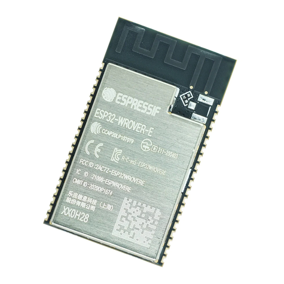
- Page 5 2. Pin Definitions 2. Pin Definitions 2.1 Pin Layout Figure 1: Pin Layout of ESP32-WROVER-E (Top View)
- Page 6 2. Pin Definitions 2.2 Pin Description ESP32-WROVER-E has 38 pins. See pin definitions in Table 3. Table 3: Pin Definitions Name Type Function Ground Power supply Module-enable signal. Active high. SENSOR_VP 4 GPIO36, ADC1_CH0, RTC_GPIO0 SENSOR_VN 5 GPIO39, ADC1_CH3, RTC_GPIO3...
- Page 7 2. Pin Definitions Name Type Function IO19 GPIO19, VSPIQ, U0CTS, EMAC_TXD0 IO21 GPIO21, VSPIHD, EMAC_TX_EN RXD0 GPIO3, U0RXD, CLK_OUT2 TXD0 GPIO1, U0TXD, CLK_OUT3, EMAC_RXD2 IO22 GPIO22, VSPIWP, U0RTS, EMAC_TXD1 IO23 GPIO23, VSPID, HS1_STROBE Ground Notice: * GPIO6 to GPIO11 are connected to the SPI flash integrated on the module and are not connected out. 2.3 Strapping Pins ESP32 has five strapping pins, which can be seen in Chapter Schematics:...
- Page 8 2. Pin Definitions Booting Mode Default SPI Boot Download Boot GPIO0 Pull-up GPIO2 Pull-down Don’t-care Enabling/Disabling Debugging Log Print over U0TXD During Booting Default U0TXD Active U0TXD Silent MTDO Pull-up Timing of SDIO Slave Falling-edge Sampling Falling-edge Sampling Rising-edge Sampling Rising-edge Sampling Default Falling-edge Output...
- Page 9 • External SRAM can be mapped into CPU data memory space. Up to 4 MB can be mapped at a time. 8- bit, 16-bit and 32-bit reads and writes are supported. ESP32-WROVER-E integrates a 8 MB SPI flash and an 8 MB PSRAM for more memory space. 3.3 Crystal Oscillators...
- Page 10 3. Functional Description 3.4 RTC and Low-Power Management With the use of advanced power-management technologies, ESP32 can switch between different power modes. For details on ESP32’s power consumption in different power modes, please refer to section ”RTC and Low- Power Management” in ESP32 Datasheet.
- Page 11 4. Peripherals and Sensors 4. Peripherals and Sensors User,Manual. Please refer to Section Peripherals and Sensors in ESP32 Note: External connections can be made to any GPIO except for GPIOs in the range 6-11, 16, or 17. GPIOs 6-11 are connected to the module’s integrated SPI flash and PSRAM.
- Page 12 5. Electrical Characteristics 5. Electrical Characteristics 5.1 Absolute Maximum Ratings Stresses beyond the absolute maximum ratings listed in the table below may cause permanent damage to the device. These are stress ratings only, and do not refer to the functional operation of the device that should follow the recommended operating conditions.
- Page 13 5. Electrical Characteristics Symbol Parameter Typ Max Unit Low-level sink current (VDD = 3.3 V, V = 0.495 V, output drive strength set to the maximum) Resistance of internal pull-up resistor kΩ Resistance of internal pull-down resistor kΩ Low-level input voltage of CHIP_PU to power off the chip nRST Notes: 1.
- Page 14 5. Electrical Characteristics 5.5 Bluetooth/BLE Radio 5.5.1 Receiver Table 9: Receiver Characteristics – Bluetooth/BLE Parameter Conditions Unit Sensitivity @30.8% PER –97 Maximum received signal @30.8% PER Co-channel C/I F = F0 + 1 MHz –5 F = F0 – 1 MHz –5 F = F0 + 2 MHz –25...
- Page 15 5. Electrical Characteristics 5.6 Reflow Profile Peak Temp. 235 ~ 250 Preheating zone Cooling zone Reflow zone 150 ~ 200 60 ~ 120s !217 60 ~ 90s -1 ~ -5 /s Soldering time > 30s Ramp-up zone 1 ~ 3 /s Time (sec.) Ramp-up zone —...
- Page 16 6. Learning Resources Learning Resources 6.1 Must-Read Documents The following link provides documents related to ESP32. • ESP32 User Manual This document provides an introduction to the specifications of the ESP32 hardware, including overview, pin definitions, functional description, peripheral interface, electrical characteristics, etc. •...
- Page 17 Revision History Revision History Date Version Release notes Preliminary release for certification CE&FCC 2020.01 V0.1 OEM Guidance 1. Applicable FCC rules This module is granted by Single Modular Approval. It complies to the requirements of FCC part 15C, section 15.247 rules. 2.
- Page 18 Antenna Antenna type: PCB antenna Peak gain: 3.40dBi Omni antenna with IPEX connector Peak gain2.33dBi 7. Label and compliance information An exterior label on OEM’s end product can use wording such as the following: “Contains Transmitter Module FCC ID: 2AC7Z-ESP32WROVERE” or “Contains FCC ID: 2AC7Z-ESP32WROVERE.”...
Need help?
Do you have a question about the ESP32-WROVER-E and is the answer not in the manual?
Questions and answers