
Related Manuals for Ace AT Series


Summary of Contents for Ace AT Series
- Page 1 Model AT Series Rotary Accumulation Table Installation and Maintenance Manual Automated Cells & Equipment, Inc. REV 4-11-2019 9699 Enterprise Drive Painted Post, NY 14870 P: 607.936.1341 F: 607.936.1531 Page | 0...
-
Page 2: Table Of Contents
Section 1 - Introduction Table of Contents Section 1 - Introduction ..........................1 Section 2 - How to Use This Manual ......................1 Section 3 – Specifications..........................1 AT24 ................................2 AT36 ................................2 AT48 ................................3 AT60 ................................3 AT72 ................................ - Page 3 Section 1 - Introduction AC LINE & ARMATURE CONNECTION ....................13 ACCEL TRIMPOT ADJUSTMENT ......................14 DECEL TRIMPOT ADJUSTMENT ......................14 Troubleshooting ............................15 Section 9 – Contact Information ......................... 15 Page | 1...
-
Page 4: Section 1 - Introduction
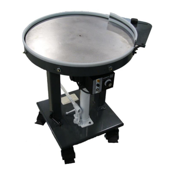
Section 1 - Introduction Section 1 - Introduction Congratulations on your purchase of the Model AT Rotary Accumulation Table. The Model AT Rotary Accumulation Tables are designed to accumulate work-in-process or finished parts. The standard turntable features variable speed rotation and a mild steel, stainless or UHMW plastic top. The following information describes the proper operation and maintenance of the AT rotary accumulation tables. -
Page 5: At24
Section 3 – Specifications AT24 24” Diameter x 11 Ga. reinforced top. Plain steel Table top top surface (no finish), powder coat on underside. Adjustable part diverter included Turntable support Low-friction turntable support bearings Medium duty DC variable speed drive, 1-8 RPM Drivetrain complete with 9 foot 120 VAC power cord Capacity... -
Page 6: At48
Section 3 – Specifications AT48 48” Diameter x 7 Ga. reinforced top. Plain steel top Table top surface (no finish), powder coat on underside. Adjustable part diverter included Turntable support Low-friction turntable support bearings Medium duty DC variable speed drive, 1-6 RPM Drivetrain complete with 9 foot 120 VAC power cord Capacity... -
Page 7: At72
Section 3 – Specifications AT72 72” Diameter x 7 Ga. reinforced top. Plain steel top Table top surface (no finish), powder coat on underside. Adjustable part diverter included Turntable support Low-friction turntable support bearings Heavy duty DC variable speed drive, 0.5-3 RPM Drivetrain complete with 9 foot 120 VAC power cord Capacity... -
Page 8: Section 4 - Unpack/Uncrate
Section 4 – Unpack/Uncrate After receiving your ACE Model AT Rotary Accumulation Table, carefully unpack the unit and check for any damage. If unit is damaged, please contact the freight company. ACE can assist you with any replacement parts you may require. -
Page 9: Height Adjustment
Section 5 – Setup Height Adjustment To adjust the working height of the Model AT upward: 1) Loosen the height adjustment locks. 2) Make sure the lift lowering valve is tight (rotate clockwise to tighten). The manual lift handle is used for tightening and loosening the lift lowering valve. -
Page 10: Applying Power
Section 6 – Operation Applying Power Uncoil the provided 9ft cord and plug into a grounded 15 Amp outlet. NOTE: Make sure the On/Off toggle switch on the controller is in the off position prior to applying power. Section 6 – Operation Power On and Speed Adjustment To power up the Model AT Rotary Accumulation Table place the POWER switch in the ON position. -
Page 11: Part Diverter Adjustment
Section 7- Safety Part Diverter Adjustment The part diverter rail moves accumulated parts to the center of the rotary table, allowing room for new parts to enter the table. The amount of offset can be adjusted by loosening the hand knob securing the diverter arm and sliding the diverter to the desired position. -
Page 12: Lubrication At24, At36
Section 8 – Maintenance Lubrication AT24, AT36 The gearbox utilized on the model AT24 and AT36 is lubricated- for-life and does not require servicing of the lubricant. Lubrication AT48, AT60, AT72 For optimum performance on the Model AT48, AT60, AT72, the gearbox oil level should be checked every month or 500 hours of operation. -
Page 13: Manual Lift
Section 8 – Maintenance Manual Lift The manual lift should not require servicing. However, if the lift is not raising the turntable, verify the lowering valve is tight. If it is still not raising the turntable, verify there is oil in unit. If low on oil, add good grade hydraulic jack oil. -
Page 14: Variable Speed Controller (Kbwm-120)
Section 8 – Maintenance Use only a load-rated lifting eye rated at a minimum of 1,000 lbs. for removal of the top. WARNING: Lifting eye and hoist should be used to remove the table top only. Do not attempt to lift the entire unit with the eye or damage may result. -
Page 15: Electrical Ratings
Section 8 – Maintenance ELECTRICAL RATINGS Part No. Input Voltage Max. AC Armature Max. DC Max. Model Number (VAC -50/60Hz) Load Current Voltage (VDC) Load Current Horsepower (RMS Amps) (DC Amps) HP, (kW) KBWM – 120 9380 0 - 90 1/3,(0.25) PLUG-IN HORSEPOWER RESISTOR®... -
Page 16: Control Layout
Section 8 – Maintenance CONTROL LAYOUT AC LINE & ARMATURE CONNECTION Page | 13... -
Page 17: Accel Trimpot Adjustment
Section 8 – Maintenance ACCEL TRIMPOT ADJUSTMENT DECEL TRIMPOT ADJUSTMENT Page | 14... -
Page 18: Troubleshooting
Troubleshooting Symptoms Corrective Action Plug power cord into an available 120VAC outlet. Turn power switch to ON position. Turntable fails to Rotate Rotate speed control knob clockwise to increase speed. Verify the 120VAC outlet is operating property. - Page 19 Is this a mechanical or electrical problem? Section 10 Recommended Spare Parts list The following section provides a list of the recommended spare parts for the Model AT Series Rotary Accumulation Table. Upon request, Automated Cells & Equipment would be happy to provide you a quote on spare parts for your Model AT Series Rotary Accumulation Table.
- Page 20 Section 10 Recommended Spare Parts list Common Spare Parts (All Models) Recommended Item Description spare Qty. E4.04169.929.BRK2 Caster - 4" Swivel, Poly HiTech Wheel, Techlock Brake CF-1 1/4-B Cam Follower - 1 1/4" Diameter with 1/2-20 Male Stud 3/16 Lube Fitting, 3930 Lbs. Dynamic Rating Capacity 1728-B Grease Fitting, #20100, 3/16"...
- Page 21 Section 10 Recommended Spare Parts list Spare Parts for AT24, AT36 Recommended Item Description spare Qty. 011-348-4200 Gearmotor - 1/8HP, 8.3 RPM at 90VDC Parallel 310 In-lbs Torque 6436K18 Shaft Collar - 1" Bore, Two-Piece, Clamp-On 1 3/4" OD x 1/2" Wide, Black Oxide Finish 2923T51 Hydraulic Jack - 1 1/2 Ton x 15 3/8"...
- Page 22 Section 10 Recommended Spare Parts list Recommended Item Description spare Qty. KBWM-120 DC Controller - 9380, 1/3HP, 120VAC In/90VDC Out 5A 120VAC AC Load, Order Proper Plug In Resistor 098002.00 Motor - 1/4HP, TENV, 1750RPM, 90VDC Removable base 1174268 Resistor - BR0050, for 782518 DC Controller Includes Fuse, for 1/4HP DC Motor VG-JS200-125-20 Guide Rail - 1/8 x 3/4"...
- Page 23 Spare Parts for AT72 Recommended Item Description spare Qty. GRG- Speed Reducer - GRG-DVLMQ832-600-RD4-56C DV32220099.00 600:1 Ratio, Double Reduction, 1.5" Dia. Output Shaft, 56-C Face, Fill Oil Level Based on Output Shaft Being Up, Mobil GlyGoyle 460 PAG Pre-filled with Vertical Low Feet Installed 098000.00 Motor - 1/2HP, TENV, 1750RPM, 90VDC Removable base...
- Page 24 Appendix A: Leeson SM4 VFD Appendix A: Leeson SM4 VFD This section contains information and settings if the AT Rotary Table is equipped with a Leeson SM4 VFD controller. SM4 Drive Parameters and Settings The SM4 is equipped with a display screen, up- down, memory, direction, start, and stop buttons.
- Page 25 Appendix A: Leeson SM4 VFD Default Parameters P100 = 0 (Local Mode) P101 = 0 (Keypad Operation) P102 = 6Hz (Minimum Freq) P103 = 50Hz (Maximum Freq) P104 = 5.0s (Accel Time) P105 = 5.0s (Decel Time) P107 = 1 (Line Voltage) P108 = 30% (MTR Overload) (Motor current/SM2 Current)*100 Motor = 0.49A...
- Page 26 Appendix B: Manufacturers Data Sheets Appendix B: Manufacturers Data Sheets This section contains any manufacturer’s data sheets available for components used within the manufacture of the Model AT Series Rotary Accumulation Table. Page | 23...
Need help?
Do you have a question about the AT Series and is the answer not in the manual?
Questions and answers