Table of Contents
Advertisement
Quick Links
Advertisement
Table of Contents

Subscribe to Our Youtube Channel
Related Manuals for Aimco iEC


Summary of Contents for Aimco iEC
- Page 1 AcraDyne iEC DC Tool Controllers User Guide...
-
Page 2: Table Of Contents
Introduction Thank you for your purchase of an AcraDyne iEC DC Tool Controller from AIMCO. The iEC represents the most advanced controller for AcraDyne series electric controlled assembly tools and is capable interfacing with all series of AcraDyne tools. This manual is designed to provide the user of the AcraDyne iEC Controller with a guide to understanding the features and functions of the controller. -
Page 3: Safety Information
Safety Information SAFETY REQUIREMENTS READ AND SAVE THESE INSTRUCTIONS WARNING! Ensure that owner/operator has read all Safety Requirements and User Manuals prior to operating. To avoid electric shock, which may result in personal injury and/or death, electrical supply must be meet the electrical requirements. -
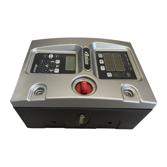
Page 4: Front Panel Diagram (Figure 1)
Front Panel Figure 1 i E C 1—Main Display Panel—Annunciation and Display programming (see Page 5 for detail) 2— Power Disconnect Switch— Turns controller on and off 3—Keypad Display Module (KDM)—Onboard Interface for setup and programming (Optional) Bottom Panel Figure 2 1—CAN Connectors—... -
Page 5: Main Display Panel Diagram (Figure 4)
Main Display Panel Figure 4 1—Rundown Feedback Indicators A—ACCEPT— Green LED indicates OK rundown B—TORQUE—Steady red indicates HI, flashing red indicates LO C—ANGLE—Steady yellow indicates HI, flashing yellow indicates LO D—CYCLE—Blue LED indicates tool is in rundown cycle 2—Primary Display Field—Displays Parameter Set Target or Rundown torque 3—Secondary Display Field—Selectable Display Choices (Angle etc…) 4—Programmable Display Selection Buttons A—Optional Display Access—Accesses the Programmable Options menu... -
Page 6: Initial Setup
Turn the controller on by rotating the Power Disconnect Switch (Figure 1, pg. 4), to the POWER ON position, represented by the symbol. When an iEC with SCC code 2.0 and higher is powered on, three messages will be shown on the dis- play: SYS INIT- indicates the system is initializing IEC “#.##”... - Page 7 3 seconds. Factory & Default Parameter Sets Before the user programs the iEC controller for the first time, or after resetting the controller to factory default settings, one of three different groups of parameters may be present in the controller: DEFAULT WITH NO TOOL CONNECTED—These parameters will start at 10 Nm and increase...
-
Page 8: Main Display Functions
Setting Parameters section in the ToolWare portion of the user manual.) Programming the Display Options The Programmable Display Options feature in the iEC allows the user to select the information that will be displayed in the Secondary Display Field. - Page 9 Main Display Functions Step 2 To scroll through the available display options, press and release the NEXT button. Repeated presses will cycle the display options as follows DFLT > ANGL > BCNT > TOT > OK > NOK > CP > CPK > JTRT The definition of each Display Option is as follows: DFLT (Default) Field is blank if a Torque Control Strategy is programmed.
-
Page 10: Display Optional Values For Individual Rundowns (Steps 1-2)
Main Display Functions Step 3 When the desired Display Option is selected, press the SET button (Fig. 4) to lock this option as the visible display. Once the SET button is pressed, the display screens will clear. Upon completing a rundown cycle, the value for the selected Display Option will be shown in the Secondary Display Field (Fig. -
Page 11: Using The Optional Keypad Display Module (Kdm)
Using the Optional Keypad Display Module (KDM) 1—KDM Display Screen 2—KDM Power On / Off Button 3—Shift Button—used to access alternate functions on highlighted buttons 4—SEND Button—Used to send new or edited parameter sets to the tool and controller 5—Numerical / Alternate Function keypad Parameter Set Terms ANGLE CONTROL / TORQUE MONITOR—Control strategy in which angle is the control parameter, but torque is monitored. -
Page 12: Turning The Kdm On / Off
ToolWare software interface program. Turning the KDM On After turning on the iEC Controller (described in Initial Set-up, Pg. 6), press the POWER button on the KDM. The following text will be shown on the KDM Display Screen: Turning the KDM Off 1) Turning off the iEC Controller (detailed in Initial Set-up, Pg. -
Page 13: Accessing Quick Start Parameter Sets
Quick Start parameter sets. Editing Quick Start Parameter Sets Depending on the number of Parameter Sets that have previously been programmed into the iEC Controller, the user will have the option of choosing from 1 to 8 parameter sets to edit. -
Page 14: Configuring New Quick Start Parameter Sets
Configuring New Quick Start Parameter Sets Depending on the number of Parameter Sets that have previously been programmed into the iEC Controller, the new parameter set will automatically be assigned a value from 2 through 8. Press the number on the KDM that corresponds to the number for the next parameter set to be configured. -
Page 15: Entering / Editing Values In The Kdm
Using the Optional Keypad Display Module (KDM) Depending on the number of Parameter Sets that have previously been programmed into the iEC Controller, the user will have the option of choosing from 1 to 8 parameter sets to edit. If the user chooses to configure a new parameter, the next set will be assigned the next available PSet value, up to 8. -
Page 16: Main Menu: 2) Calibration
The tool is now ready to be run to the appropriate target torque value. The AUTO-SET function is under development for future versions of the iEC controller. If the user exits the CONFIGURE mode before pressing all edits and modifications that have been entered will be lost and the entries will revert back to the previous value. -
Page 17: Main Menu: 3) Administration Functions
Using the Optional Keypad Display Module (KDM) Main Menu: 3) Administration Functions Parameter Set Defaults Parameter set defaults are the values used to calculate control parameters when using either Quick Start or Auto Set. This is also the area where units of measurement for all parameters is set. To access the Parameter Set Default function: From the MAIN MENU, press for ADMIN... -
Page 18: Security
The security function allows the user to set up a password in order to prevent unauthorized persons from altering the programming of the iEC controller. Once the password function is activated, the user will be prompted to enter the correct password whenever attempting to navigate past the Main Menu. -
Page 19: Tool Information
ADMIN Press for TOOL INFO Reset Factory Defaults The RESET DEFAULTS menu allows the user to quickly reset the iEC Controller setting to the original factory default values. The values that can be reset are: 1) TOOL CAL VALUE... -
Page 20: Error Codes
To cancel the reset process, press Error Codes By default, the iEC Controller only displays Error Codes in the Primary and Secondary Display Fields of the Main Display Panel (Figures 1 & 4). These errors will display automatically when recorded. Error codes are listed in Appendix A in this users guide. -
Page 21: Adaptive Control
Using the Optional Keypad Display Module (KDM) Adaptive Control ADAPTIVE CONTROL provides the user with a function to allow the iEC Controller to adapt to the joint dynamics of a particular application and to adjust the target torque accordingly in order to provide accurate and repeatable performance. -
Page 22: Networking
Networking The controller has several networking options available including Ethernet and hardwired field bus. All parameters pertaining to networking are configured in the web interface via its Ethernet. Ethernet Each Ethernet connection can be configured to communicate with most popular plant equipment includ- ing data collection servers, laptop software, and PLCs. - Page 23 Of course this action requires the existing password. If the password is lost or un- known contact your AIMCO representative for a method of retrieval. The controller has the ability to provide an FTP server to allow the transfer of stored rundown data. For security reason it is turned off by default.
- Page 24 Networking Open Protocol The controller has the ability to accept an “Open” protocol connection. This connection is available over Ethernet and/or the standard serial ports. Through this connection you can enable/disable the tool, set the active parameter set, collect rundown data, and much more. 1.
- Page 25 Networking The Controller supports the following MIDs. See the latest Open protocol specification for details on each MID. Description Note 0001 Communication start 0003 Communication stop 0010 Parameter set numbers upload request 0012 Parameter set data upload request 0013 Parameter set data upload reply 0018 Select Parameter set 0020...
- Page 26 Networking Chrysler PFCS The controller has the ability to connect to the Chrysler PFCS network. Once the controller is on the local network there are several parameters that must be set to work correctly. 1. Server IP Address: This is the IP address of the Chrysler server. If the server is on another subnet you will also have to verify the gateway in the Ethernet settings.
- Page 27 AIMCO Database The controller has the ability to send rundown data to an AIMCO data collection server. Once the con- troller is on the local network there are two parameters that must be set to store data correctly on the server.
- Page 28 Networking Modbus TCP The controller will accept a connection from a Modbus TCP master. Controller Outputs The Controller’s outputs are located at address 0 and contain one status word. Controller Outputs Bits 14 13 Handshake Job Complete Healthy Running Process number Address 0 Name Function...
- Page 29 Networking Profibus/DeviceNET The controller can have an optional Profibus or DeviceNET interface. These interfaces are accom- plished through the use of a serial bridge. The serial bridge is provided by MKS Instruments, Inc . See the latest MKS documentation for details on sending and receiving messages. Logical I/O The controller has five status bytes of outputs.
- Page 30 Networking Byte Name Function PSET Set the active parameter set of 1-32. If 0 the active parameter set is left unchanged. Tool Enable If PLC Enable is 0 this input is ignored. If PLC Enable is 1 this bit can be used to enable or disable the tool.
- Page 31 Networking Optionally the controller can include the fastening results in the output image. Including the fastening results increases the output size to thirty four bytes of data. Controller Outputs Tool Tool Ready Enable Batch Status Status Bypass Com- plete Final Torque (Real) Torque Low Limit (Real) Byte 10-13...
- Page 32 Networking The reading of the results data should be done at the rising edge of the “Status OK” and “Status NOK”. This will insure the correct results are captured consistently. All the results are zeroed after the “Status OK” and “Status NOK” are turned off. The controller consumes thirty two bytes of inputs (Assembly instance 112).
-
Page 33: Error Proofing
Error Proofing Barcode Reader The max length of a barcode is 20 characters if it is longer the leading characters will be lost and the last 20 will be used. Since barcode readers send their characters in burst there is no need to program in a length. -
Page 34: Appendix A Error Codes And Descriptions
APPENDIX A: Error Codes & Descriptions Error Code # Fault Description AUT1 TID Timeout Tool ID board communication timeout Tool GND Ground circuit problem between controller and tool Power On Throttle RUN command on during power up Button Timeout Button (run, fwd, rev) communication timeout Button State Illegal button state (example fwd and rev) Undefined Voltage... -
Page 35: Appendix B Menu Structures Of Kdm
Appendix B: KDM Menu Structures Main Menu Structure Parameter Set-up Menu... - Page 36 APPENDIX B: KDM Menu Structures Administration Menu...
-
Page 37: Appendix C I/O Diagram & Definitions
By referencing the diagram below , the user can access the controllers I/O functions for a variety of line control and error proofing functions. A connector kit is available (PT # 23490) from AIMCO to make connection to the I/O port on the iEC controller easier; contact your AIMCO sales representative for ordering information. - Page 38 APPENDIX C: I/O Diagram & Definitions LOGIC I/O CONNECTIONS NOTE: Turn off the system before connecting to the LOGIC I/O port. There may be risk of damaging the controller. 24Vdc Supply: The internal 24Vdc power can supply up to 2 amps. Inputs: The inputs are a sinking configuration with the common connected to the ground pins.
- Page 39 APPENDIX C: I/O Diagram & Definitions I/O Definitions Output 1, Accept DB25 pin 1. The relay closes after achieving the target torque or target angle. The output is programmable for latched or timed operation using ToolWare. Output 2, Reject DB25 pin 2. The relay closes if the final torque or angle is outside of the High/Low limits. The output is programmable for latched or timed operation using ToolWare.
- Page 40 APPENDIX C: I/O Diagram & Definitions Analog In 2 DB25 pin 20. Analog input 2, for future use. Input 1, Run Forward DB25 pin 6. Runs tool forward. Buttons from I/O must be selected using ToolWare. Input 2, Run Reverse DB25 pin 7.
-
Page 41: Appendix D Light Assignment For Light Tower And Key Bypass
APPENDIX D: Light Assignment for Light Tower and Key Bypass Light Color Judgment Green Accept High Torque Red Flashing Low Torque Yellow High Angle Yellow Flashing Low Angle Blue Bypass White Tool Enabled White Flashing Assignable Lights Strobe Assignable APPENDIX E: Dual Trigger Lever Functionality for Gen 3-4 tools •... -
Page 42: Appendix Ftube Nut Homing Sequence
APPENDIX F: TUBE NUT Homing Sequence • Tubenut Homing Option: Home on Release and Repress of Trigger: • If Single Trigger Lever: • Once the rundown is complete, releasing the lever and pressing it again is required to return the socket to home. •... -
Page 43: Appendix G Frequently Asked Questions
APPENDIX G: FAQ’S Q: HOW CAN I IMPROVE THE TOOL’S REPEATABILITY? Generally speaking, slowing the tool down will improve its repeatability. Reducing the RPM FREE% value will give the tool more time to react as it approaches the target torque. Reducing the DOWNSHIFT TQ and/or RPM DOWN% may also have the same effect. - Page 44 Ethernet system, ToolWare can be used to conduct a wide range of programming, diag- nostic and analytical procedures. For more information on ToolWare, refer to the Tool- Ware Users Guide section of this manual or contact your AIMCO sales representative.
-
Page 45: Appendix H Toolware Users Guide - Separate Table Of Contents
Notes:... - Page 46 Notes:...
- Page 47 Notes:...
- Page 48 AIMCO CORPORATION DE MEXICO SA DE CV CORPORATE HEADQUARTERS Ave. Cristobal Colon 14529 10000 SE Pine Street Chihuahua, Chihuahua. 31125 Portland, Oregon 97216 Mexico Phone: (503) 254–6600 Phone: (01-614) 380-1010 Toll Free: 1-800-852-1368 Fax: (01-614) 380-1019 LIT-MAN921 Rev. 07/2020 Printed in USA ©2020 AIMCO...
Need help?
Do you have a question about the iEC and is the answer not in the manual?
Questions and answers