
Subscribe to Our Youtube Channel
Related Manuals for Aimco AcraDyne


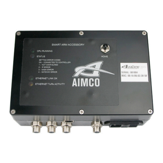
Summary of Contents for Aimco AcraDyne
- Page 1 Gen IV Controller with Smart Arm Setup Instruction Manual 10000 SE Pine St., Portland, OR 97216 • 800-852-1368 • 503-254-6600 • Fax 800-582-9015 www.aimco-global.com...
-
Page 2: Table Of Contents
4.1 Connecting the Encoders . Equipment/Software 4.2 Encoder Compatibility . 4.3 Connecting the Remote Home . • AIMCO Gen 4 controller. • Power Supply Cable. 5. Care Setup Steps Overview . • Smart Arm Accessory – Encoder Interface - 30860 6. -
Page 3: Hardware Connection
Gen IV Controller with Smart Arm Setup Instruction Manual Hardware Connection Care Setup Steps Overview Connecting the Encoders This document covers the details of interfacing an arm outfitted with encoders to a Gen IV Controller. The encoders from the arm connect to the controller The general steps of the setup are: via M12 connectors. -
Page 4: Configuration Of The Smart Arm Accessory
Gen IV Controller with Smart Arm Setup Instruction Manual 7. Configuration of the Smart Arm Accessory Accessory Setup Screen 7.1 Configuration Overview To configure the Smart Arm Accessory, from the The smart arm and runscreen can be configured in main Gen IV controller screen, select "Accessories." many different ways to fit the user’s needs. -
Page 5: Accessory Scanning And Ip Setup Screen
This screen is used to configure the IP settings of the accessory. Clicking the magnifying glass will search for AcraDyne Accessories on the network. Any The primary setup screen contains the basic settings accessories found will show up in the list. Click on the for what action will be taken when the arm is in accessory to be configured to edit its settings. -
Page 6: Encoder Position Setup
Gen IV Controller with Smart Arm Setup Instruction Manual • Part Image ID: Shows a list of images that have 7.5.2 Encoder Location Setup Screen been added • Part Images: This section allows you to add, To enter the edit or delete custom images for the Smart Arm encoder location Runscreen. -
Page 7: Smart Arm Runscreen
Gen IV Controller with Smart Arm Setup Instruction Manual • Use Current Position: Selecting this option will Enter a unique identifier as the Part Image Name grab the current state of the encoders and use it and click "Choose File" to navigate to and select as the target. -
Page 8: Associate An Image With A Job
Gen IV Controller with Smart Arm Setup Instruction Manual Associate an Image with a Job On the Edit Job screen, select Advanced Options Once a smart arm accessory and part images have been set up, you can associate a job with a specific smart arm part image in the controller's Job interface. -
Page 9: Examples
Gen IV Controller with Smart Arm Setup Instruction Manual ▪ The Jobs screen gives the option to Enable or Controller IP Address: 192.168.100.1 ▪ Disable jobs. Click to toggle between the two. Subnet: 255.255.255.0 • Set up the accessory ethernet settings Go to the Accessory screen and click the ○... -
Page 10: Accessory Setup
Gen IV Controller with Smart Arm Setup Instruction Manual 9.1.2 Accessory Setup controller over a web connection. Image must be 470 x 550 pixels for best fit to controller screen. Navigate to the Accessories screen, select the Smart Arm accessory configured in the ‘Initial Setup’ portion and click the edit button. -
Page 11: Icon Reference
Gen IV Controller with Smart Arm Setup Instruction Manual 9.1.4 Icon Reference an associated location then the active location will turn blue indicating the current position and the active PSet will change. Icon Function Definition Current The encoder states match the Location encoder location tied to this smart Image 2... -
Page 12: Pset Setup
Gen IV Controller with Smart Arm Setup Instruction Manual 9.2.1 PSet Setup The setup should result in a job that is shown below. Set up six PSets. These can be named in the advanced settings to make it more clear which PSet is for which bolt. -
Page 13: External Control
Gen IV Controller with Smart Arm Setup Instruction Manual 9.2.4 External Control Image 5 Line side control can be used to command which Job Seq 2 is selected. fastener needs to be run. Select the Job that Arm is in position matches the work type (initial or rework) and 1 (shown in red as select the job sequence number that is tied to the... -
Page 14: Clearing Locations
Gen IV Controller with Smart Arm Setup Instruction Manual 11. Icon Reference Image 8 All fasteners inserted. Icon Function Definition Tool is disabled. Status bar shows job Position not The current position of the arm does not valid match any locations in the smart arm complete. - Page 16 AIMCO CORPORATE HEADQUARTERS AIMCO CORPORATION DE MEXICO SA DE CV 10000 SE Pine Street Ave. Cristobal Colon 14529 Portland, Oregon 97216 Chihuahua, Chihuahua. 31125 Phone: (503) 254–6600 Mexico Toll Free: 1-800-852-1368 Phone: (01-614) 380-1010 Fax: (01-614) 380-1019 LIT-MAN275 Rev. 07-26-22...
Need help?
Do you have a question about the AcraDyne and is the answer not in the manual?
Questions and answers