Advertisement
Advertisement
Table of Contents

Subscribe to Our Youtube Channel
Related Manuals for Aimco UEC-4800EX


Summary of Contents for Aimco UEC-4800EX
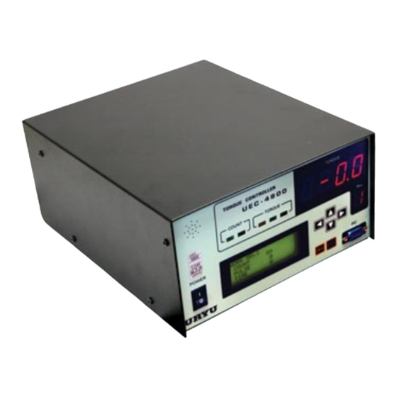
- Page 1 UEC-4800EX Upgrade INSTRUCTION MANUAL...
- Page 3 DISASSEMBLY OF UEC-4800 BILL OF MATERIALS PART NUMBER QTY DESCRIPTION UEC-4800 Torque Controller 1. Remove the four screw on both sides of the UEC-4800. 2. Remove the two screws that hold the front panel to the UEC-4800. 3. Remove the cover of the UEC-4800. 4.
- Page 4 QTY DESCRIPTION UEC-4800 Torque Controller UEC-4800EX-UPGRADE 1. Find the TB1 connector, unplug it, and cut the wire tie holding it in place. 2. Install the two green w/yellow striped wires from the power interface cable to the ground rail. 3. Connect the power interface cable to the TB1 connector.
- Page 5 UEC-4800 Torque Controller UEC-4800EX-UPGRADE 1. Install the front panel back in to the board on the UEC, secure tightly. 2. Install the top cover assembly to the UEC and reinstall the eight screw that hold the cover in place, making sure not to pinch the wires coming out of the back.
- Page 6 UEC-4800 Torque Controller UEC-4800EX-UPGRADE 1. Connect the UEC null modem cable to the DB9 PC plug on the back of the UEC. 2. Connect the I/0 cable to the I/O terminal block top row on the back of the UEC, black wire to COM (upper)/IN COM, red wire to LS1/IN6, white wire to RESET/IN3, green wire to work A/IN4, and yellow wire to work B/IN5.
- Page 7 Revision History: Revision Date: 11/04/2013 Document Change Log: Initial Release...
- Page 8 AIMCO CORPORATE HEADQUARTERS AIMCO CORPORATION DE MEXICO SA DE CV 10000 SE PINE STREET AVE. CRISTOBAL COLON 14529 PORTLAND, OREGON 97216 CHIHUAHUA, CHIHUAHUA. 31125 PHONE: (503) 254–6600 MEXICO TOLL FREE: 1-800-852-1368 PHONE: (01-614) 380-1010 FAX: (01-614) 380-1019 LIT-MAN175 REV. 07/2020...
Need help?
Do you have a question about the UEC-4800EX and is the answer not in the manual?
Questions and answers