
Subscribe to Our Youtube Channel
Related Manuals for Aimco AcraDyne Gen IV iAC


Summary of Contents for Aimco AcraDyne Gen IV iAC
- Page 1 Gen IV iAC Controller Operation Manual 10000 SE Pine St., Portland, OR 97216 • 800-852-1368 • 503-254-6600 • Fax 800-582-9015 www.aimco-global.com...
-
Page 2: Table Of Contents
AcraDyne Gen IV iAC Controller Manual Table of Contents 1. Safety Information 4.5.8 Set Time . . 30 4.5.9 Remote Connections . . 30 2. Controller Diagram . 4.5.10 Languages . . 30 Bottom Panel iAC Basic Model . Accessories . -
Page 3: Safety Information
Remove any adjusting key or wrench before qualified technician using only original spare parts, turning the power tool on. available from AIMCO. This ensures that the safety e. Do not overreach. Keep proper footing and of your device is maintained. -
Page 4: Controller Diagram
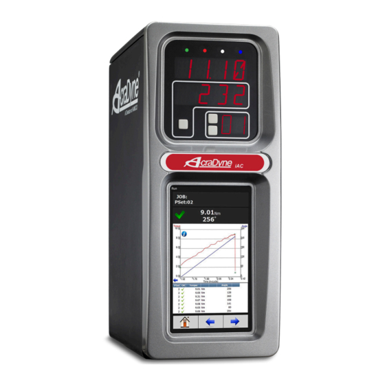
AcraDyne Gen IV iEC Controller Manual AcraDyne Gen IV iAC Controller Manual 2. Controller Diagram Bottom Panel iAC Basic Model External Shutoff Valve Solenoid Connection 24 Volt terminal Tool Connector Power Disconnect Switch- Turns controller power on and off Power Supply Cord Connection... -
Page 5: Top Panel Iac Models With Shutoff Valve And/Or Regulator
AcraDyne Gen IV iAC Controller Manual Top Panel iAC Models with Shutoff Valve and/or Regulator Air Outlet to the tool – ½” NPT (top exit versions) Tool Connector (top exit versions) Air Supply Inlet to the tool 130 PSI maximum – ½”NPT Air Exhaust –... -
Page 6: Initial Setup
Typical Air Connections for SR Models equipped with to connect to local 230Vac power outlets. AIMCO Internal Shutoff Valve and Digital Pressure Regulator has a wide variety of country specific power cord options available. -
Page 7: Interfacing With The Controller
AcraDyne Gen IV iAC Controller Manual Typical Air Connections for S Models equipped with Interfacing with the Controller Internal Shutoff Valve There are three ways to program/communicate with Air Supply the controller: • Controller touch-screen console Filter • System Port: (USB connection) Direct connection to controller. - Page 8 AcraDyne Gen IV iAC Controller Manual Step 4: Go to ‘Network and Internet’. Step 7: Find the Local Area Connection that is using the ‘USB Ethernet/RNDIS Gadget’ network. Right click this network and go to ‘Properties’. Step 8: In Properties window select ‘Internet Protocol Version 4’...
-
Page 9: Enter Tool Information Into The Controller
AcraDyne Gen IV iAC Controller Manual You will see the controller software on your computer screen. NOTE: Controller does not have a DHCP client, it will not automatically configure itself with a usable IP address. Consult your Network Administrator for configuring a correct IP address for your network. -
Page 10: Home Page (Main Menu)
AcraDyne Gen IV iAC Controller Manual 4. Home Page (Main Menu) Graph displays curves representing Torque (black trace) and Angle (blue trace). The blue left arrow at the origin of the graph will change the X-axis of the rundown curve from Time (In-Cycle) to Time (Overall) and Angle. - Page 11 AcraDyne Gen IV iAC Controller Manual Large Screen Indicators and Audit information The large screen indicators are helpful in viewing real time results of the rundown from a distance. Example of Accepted Job Example of Failed Job...
-
Page 12: Pset
AcraDyne Gen IV iAC Controller Manual PSet Time Limit (s): Maximum allowable time (in seconds) tool is allowed to run after going ‘In Cycle’. Parameter Settings (PSets) control the fastening process. The following describes the different Advanced Options: (see "4.2.4 Advanced Options"... -
Page 13: Pset Stages
AcraDyne Gen IV iAC Controller Manual 4.2.2 PSet Stages 4.2.2.1 TC_PM Torque Control Pulse Monitor Torque High: Upper control limit of the rundown. Torque Target: Final desired torque (CUT Level). Torque Low: The lower control limit of the rundown. Pulse Bailout: Total number of pulses never to be exceeded. Helps to illustrate how far past Pulse High the rundown experienced without damaging the part or excessively wearing the tool’s pulse fluid. -
Page 14: Tc_Apm Torque Control Angle Pulse Monitor
AcraDyne Gen IV iAC Controller Manual 4.2.2.2 TC_APM Torque Control Angle Pulse Monitor Torque High: Upper control limit of the rundown. Torque Target: Final desired torque (CUT Level). Torque Low: The lower control limit of the rundown. Angle Bailout: Determines when to stop the tool on angle during any Torque Control strategy. -
Page 15: Tc_Am Torque Control Angle Monitor
AcraDyne Gen IV iAC Controller Manual 4.2.2.3 TC_AM Torque Control Angle Monitor Torque High: Upper control limit of the rundown. Torque Target: Final desired torque (CUT Level). Torque Low: The lower control limit of the rundown. Angle Bailout: Determines when to stop the tool on angle during any Torque Control strategy. -
Page 16: Edit Pset
AcraDyne Gen IV iAC Controller Manual 4.2.3 Edit PSet If further Stage changes are needed click the On Home page press Edit button again to enter Edit Stage screen (below). On the PSet screen click on the desired PSet you would like to edit. -
Page 17: Manage Psets
AcraDyne Gen IV iAC Controller Manual 4.2.5 Manage PSets This timer starts when the final stage of the PSet is complete. Torque Read Delay: The primary use of this timer is to ignore seating torque or early stray pulses from contributing to the rundown results. -
Page 18: Multistage Rundown Evaluation And Reporting
AcraDyne Gen IV iAC Controller Manual 4.2.6 Multistage Rundown Evaluation and Reporting A Job is a collection of PSets which can be run when performing multiple fastening operations on a single • If a rundown cycle completes, or is terminated application. -
Page 19: Advanced Options
AcraDyne Gen IV iAC Controller Manual These generated NOK results are treated like any After appropriate values are entered, press to go other fastening. They are displayed on the run screen, to Add New Job Sequence screen. stored in the results and transmitted on all protocols. -
Page 20: Results
AcraDyne Gen IV iAC Controller Manual Results 4.4.1 Saving Rundown(s) This screen Click on in main rundown screen to view/save provides a history total rundowns. of rundowns performed. Information such Then click on on the PC as ID Number, to save or open the file using a text editor such as Time Stamp, Notepad. -
Page 21: Controller
AcraDyne Gen IV iAC Controller Manual Controller The controller menu is where all of the settings for the Gen IV controller are configured. All of the different configuration capabilities are explained in the following sections. 4.5.1 Tool Setup In this screen user can enable/ disable various tool functions. -
Page 22: Disassembly
AcraDyne Gen IV iAC Controller Manual 4.5.1.2 Disassembly Report Disassembly: If enabled, disassembly events will be reported and logged. Threshold Torque: Disassembly will be reported only if this torque value is reached. This is entered as a positive value. Torque Units: Units for the Disassembly Threshold Torque... -
Page 23: Physical Io
AcraDyne Gen IV iAC Controller Manual 4.5.2 Input Configuration Output Configuration See "11. Assignable I/O" on page 47 for more details on available assignment functions and how to configure. See "10. 24 Volt I/O" on page 16 for the pinout of the 24Volt Logic IO port, and wiring examples. -
Page 24: Anybus/Modbus Tcp/Ethernet Ip Inputs
AcraDyne Gen IV iAC Controller Manual 4.5.2.3 Anybus/Modbus TCP/Ethernet IP Inputs These types of communication are useful for data communication between controller and PLCs. It is an effective, quick way for the data transfer of short data packages. Element Type: Choose from Byte, Int16, Int32, or ASCII. -
Page 25: Anybus/Modbus Tcp/Ethernet Ip Outputs
AcraDyne Gen IV iAC Controller Manual 4.5.2.4 Anybus/Modbus TCP/Ethernet IP Outputs Element Type: Choose from Byte, Int16, or Int32. Element: Shows Element # being configured. Bit: Enter Bit # Bits (not shown): # of bits the assignment will read. Start at (not shown): Starting bit location. -
Page 26: Ethernet
AcraDyne Gen IV iAC Controller Manual 4.5.3 Communication Interfaces 4.5.3.2 Second Ethernet 4.5.3.1 Ethernet 4.5.3.3 System Port IP Address: IP Address: The IP address of IP address of controller’s controller’s System Ethernet port. Port (Default is 192.168.1.4) Subnet Mask: Subnet mask of Subnet Mask: The the controller. -
Page 27: Serial
AcraDyne Gen IV iAC Controller Manual 4.5.3.4 Serial Port Mode: The following modes are available: • PI Line Control: This is customer specific. Please reference PI Line Control Document on AIMCO Website/ 4.5.3.5 Anybus Product Manuals. • Serial Output: Node Address:... - Page 28 AcraDyne Gen IV iAC Controller Manual Serial Output Format Options Standard Output Format: ○ O: Overall Pass/Fail ▪ • O P HHHHH LLLLL TTTTT P HHHHH LLLLL AAAAA CR CR NULL* ‘P’ = Pass, ‘F’ = Fail ○ ○ O: Overall Pass/Fail P: Torque Pass/Fail ▪...
-
Page 29: Protocols
AcraDyne Gen IV iAC Controller Manual 4.5.4 Protocols 4.5.7 Bar Code Setup Required Identifiers for Tool Enable: Selects which four Identifiers (ID#1-4) are required to enable tool. information Reset Identifiers on Job Complete: Selects which four about these Identifiers (ID#1-4) to reset on a job complete. Select settings, see Identifiers by clicking on them. -
Page 30: Set Time
AcraDyne Gen IV iAC Controller Manual Example: To configure Serial Port for Barcode Reader: On Home page click Controller → Communication Interfaces → Serial VIN#123456 Select Barcode Reader and the correct Baud rate. Identifier Type: Identifies which identifier (ID#1-4) received barcode will be stored into. -
Page 31: Accessories
AcraDyne Gen IV iAC Controller Manual Accessories 4.7.1 Controller Overview Model Number: This screen shows Model Number accessories of the controller. configured in the controller. Serial Number: New accessories Serial Number of can be added, the controller. edited, and deleted using the... -
Page 32: Live Tool
AcraDyne Gen IV iAC Controller Manual Bus Voltages: Alarm icon will appear on controller Encoder Signals will be monitored along with tool RPM. console and under “Active Faults” (see below) if any (Only applies for tools with Angle Sensing capability of these values are out of range: ‘Resolver’) -
Page 33: Record Logs
AcraDyne Gen IV iAC Controller Manual 4.7.6 Record Logs 4.7.8 I/O Diagnostics Logs information The I/O Diagnostics screen shows a log of all IO state describing usage changes from any assignable input or output. This of controller and can aid in verifying the correct functionality for IO tools that have configuration. -
Page 34: Login
AcraDyne Gen IV iAC Controller Manual Advanced Login When a password is required it can be ‘Advanced’ menu handles entered in this complex screen. settings within the controller. Three levels of access to the controller are available: Detailed descriptions • Operator: Run/Login screens available. -
Page 35: Results Archive
AcraDyne Gen IV iAC Controller Manual 4.9.2 Results Archive Approximately one million rundowns can be stored. Twenty Select a files with approximately 50,000 rundowns are maintained file and at a time. The user can, at any time, save the runs to either... -
Page 36: Import Settings
AcraDyne Gen IV iAC Controller Manual 4.9.3 Import Settings 4.9.4 Export Controller This allows the user to download any previously This allows the saved settings onto the controller (refer to ‘Export user to save Controller’ for help with saving data). -
Page 37: Backup Restore
AcraDyne Gen IV iAC Controller Manual 4.9.7 Restore Factory Defaults After the controller restarts, the user should see following messages This allows the user to reset the controller’s parameters to factory settings 1. From the Home screen, navigate to Advanced →... -
Page 38: Previous Software
AcraDyne Gen IV iAC Controller Manual 4.9.8 Previous Software 5. Press to proceed. The ‘Previous Software’ page enables users to change the software to In the case an alternate of custom version. When calibration, the controller is a screen will... -
Page 39: Barcode Reader Details
AcraDyne Gen IV iAC Controller Manual 5. Barcode Reader Details Mask The iAC controller supports the following barcode reader functionality: The Mask is a string used to compare against the received barcode. The received barcode must be • Support up to four identifiers. - Page 40 AcraDyne Gen IV iAC Controller Manual The tool enable/disable will be controlled by the Once all three scans are received, the tool will be enabled. job settings; the correct job will be selected by the barcode scan. The “ID Required to Enable the Tool”...
-
Page 41: Glossary Of Terms
AcraDyne Gen IV iAC Controller Manual 6. Glossary of Terms In-Cycle Controller begins to monitor tool for angle Accept Tone Controls tone made from handle of Torque at a preselected threshold torque. Any handheld tools for accepted fastening increase in angle, after the In-Cycle point, cycles. - Page 42 AcraDyne Gen IV iAC Controller Manual 7. Icons Defined Icon Description Function Where Used Home Navigation Button Navigate to the main menu (“HOME”) screen. All screens except for edit screens. Run Navigation Button Navigate to the Run Screen. All screens except for edit screens.
-
Page 43: Stop Codes
AcraDyne Gen IV iAC Controller Manual 8. Stop Codes If a Stop condition is detected that prevents the tool from running, a code will appear on the LED display. Any active stop conditions are also displayed on the RUN screen. -
Page 44: Error Codes
AcraDyne Gen IV iAC Controller Manual 9. Error Codes If an error condition is detected that prevents the tool from running, a fault code will appear on the LED display. Any active faults are also displayed on GUI RUN screen. Fault history can be viewed in the Controller Error Log. -
Page 45: Volt I/O
10.1 Port Pinout and Diagrams 10.2 24 Volt I/O Connections An I/O wiring adapter kit is available (Part #27348) from AIMCO to make connection to I/O port on Turn off system before connecting to the LOGIC I/O the controller easier. Contact your AIMCO Sales port. - Page 46 AcraDyne Gen IV iAC Controller Manual Importing I/O on an iEC4 5. Choose file and select ONLY I/O These instructions detail how to import I/O into an iEC4 controller via the system port to modify the Anybus outputs. 1. Power on the controller 2.
-
Page 47: Assignable I/O
AcraDyne Gen IV iAC Controller Manual 11. Assignable I/O The Gen IV controller supports assignable I/O. All assignments have a bus, element, and bit configuration to define its location in the system. Buses The bus value needs to be set from the list above. - Page 48 AcraDyne Gen IV iAC Controller Manual Polarity Stop Supported Feature When the polarity is set to N.O. the input is Bus Element Bit 0-31 Polarity N.O./N.C. Width Offset considered active high (24vdc for physical inputs √ √ √ √ and logic 1 for all network type buses). When the polarity is set to N.C.
- Page 49 AcraDyne Gen IV iAC Controller Manual Select Job Sequence Set ID (word swap) Supported Feature Supported Feature Bus Element Bit 0-31 Polarity N.O./N.C. Width Offset Bus Element Bit 0-31 Polarity N.O./N.C. Width Offset √ √ √ √ √ √ √...
- Page 50 AcraDyne Gen IV iAC Controller Manual Log Change ASCII ID Supported Feature Supported Feature Bus Element Bit 0-31 Polarity N.O./N.C. Width Offset Bus Element Bit 0-31 Polarity N.O./N.C. Width Offset √ √ √ √ √ √ The “Log Change” assignment will add entries to the Abort Job controller event log when the input changes.
- Page 51 AcraDyne Gen IV iAC Controller Manual Outputs All output assignments have a Bus, Element, and Bit configuration to define its location in the system. Along with the basic configuration many also have other configuration(s) that allow its behavior to be modified to suit the application.
- Page 52 AcraDyne Gen IV iAC Controller Manual Polarity When the polarity is set to N.O. the output will be high when it is active (24vdc for physical outputs and logic 1 for all network type buses). When the polarity is set to N.C. the output will be low for active (0vdc for physical inputs and logic 0 for all network type buses).
- Page 53 AcraDyne Gen IV iAC Controller Manual Output Assignments Supported Feature Polarity Mode Input Input Input Element 0-32 N.O./N.C. Normal, Timed, Flash Time Width Offset Element √ √ √ √ √ The “Ok” output assignment will go active at the completion of an acceptable fastening. It will go inactive when the next fastening is started (the torque exceeds the threshold value) or a Job reset.
- Page 54 AcraDyne Gen IV iAC Controller Manual Low Angle Supported Feature Polarity Mode Input Input Input Element 0-32 N.O./N.C. Normal, Timed, Flash Time Width Offset Element √ √ √ √ √ The “Low Angle” output assignment will go active at the completion of a fastening that has a low angle results.
- Page 55 AcraDyne Gen IV iAC Controller Manual Error Supported Feature Polarity Mode Input Input Input Element 0-32 N.O./N.C. Normal, Timed, Flash Time Width Offset Element √ √ √ √ √ The “Error” output assignment will be active while the controller has an error.
- Page 56 AcraDyne Gen IV iAC Controller Manual PFCS Connected Supported Feature Polarity Mode Input Input Input Element 0-32 N.O./N.C. Normal, Timed, Flash Time Width Offset Element √ √ √ √ √ The “PFCS Connected” output assignment will be active if the controller has an active PFCS connection.
- Page 57 AcraDyne Gen IV iAC Controller Manual Torque (x100) Supported Feature Polarity Mode Input Input Input Element 0-32 N.O./N.C. Normal, Timed, Flash Time Width Offset Element √ √ √ √ The “Torque (x100)” output assignment will output the final torque value of the most recent rundown. The value will be cleared to 0 at the start of a new fastening cycle or a Job reset.
- Page 58 AcraDyne Gen IV iAC Controller Manual Pulses Ok Supported Feature Polarity Mode Input Input Input Element 0-32 N.O./N.C. Normal, Timed, Flash Time Width Offset Element √ √ √ √ √ The “Pulses Ok” output assignment will go active at the completion of a fastening that has an acceptable pulse count.
-
Page 59: Controller Supported Mids
AcraDyne Gen IV iAC Controller Manual 11.1 Controller Supported MIDs Supported MID Supported MID MID Description Revisions Note MID Description Revisions Note Communication start 1,2,3 Alarm subscribe Communication start 1,2,3 Alarm acknowledge Alarm acknowledge Communication stop Alarm unsubscribe Command error... -
Page 60: Open Protocol Message Ids
AcraDyne Gen IV iAC Controller Manual 12. Open Protocol Message IDs Open Protocol Supported MID Open Protocol Supported MID MID Description Revisions Note MID Description Revisions Note Communication start 1,2,3 Old tightening result upload Communication start 1,2,3 reply acknowledge Alarm subscribe... -
Page 61: Dimensions
AcraDyne Gen IV iAC Controller Manual 13. Dimensions 14. Specifications Mechanical: Air Connections (models with internal shutoff valve and/or electronic regulator) Dimensions Width: 6.25 in 159 mm Height: 15.75 in 400 mm Supply Air Inlet: 130 PSI Maximum, Fitting Type: 1/2”... -
Page 62: Troubleshooting
AcraDyne Gen IV iAC Controller Manual 15. Troubleshooting Issue: SD Card initializing Step 2: Right click on Computer and select Manage. From System Tools, select Device Manager. It will Solution: The rear SD card can be used to easily show a list of devices currently connected with the move the software, firmware, configuration, and development PC. - Page 63 AcraDyne Gen IV iAC Controller Manual Step 6: In the Select Network Adapter window, select Microsoft Corporation from the Manufacturer list. Under the list of Network Adapter, select Remote NDIS Compatible Device. Step 7: The RNDIS Kitl device is now installed and...
-
Page 64: Aimco Warranty
OR OTHERWISE. THIS EXCLUSION ALSO INCLUDES ANY agents. AIMCO shall have no obligation pursuant LIABILITY WHICH MAY ARISE OUT OF THIRD PARTY to the AIMCO Warranty with respect to any tools or CLAIMS AGAINST BUYER. THE ESSENTIAL PURPOSE OF accessories which in AIMCO’s sole judgment have... - Page 68 AIMCO CORPORATE HEADQUARTERS AIMCO CORPORATION DE MEXICO SA DE CV 10000 SE Pine Street Ave. Cristobal Colon 14529 Portland, Oregon 97216 Chihuahua, Chihuahua. 31125 Phone: (503) 254–6600 Mexico Toll Free: 1-800-852-1368 Phone: (01-614) 380-1010 Fax: (01-614) 380-1019 LIT-MAN177iAC Rev. 07/31/20...
Need help?
Do you have a question about the AcraDyne Gen IV iAC and is the answer not in the manual?
Questions and answers