Aimco AcraDyne Gen IV Operator's Manual
Hide thumbs
Also See for AcraDyne Gen IV:
- Operation manual (60 pages) ,
- Operation manual (64 pages) ,
- Setup and instruction manual (12 pages)
Table of Contents
Advertisement
Quick Links
Advertisement
Table of Contents

Related Manuals for Aimco AcraDyne Gen IV


Summary of Contents for Aimco AcraDyne Gen IV
- Page 1 Gen IV Controller Operator Manual Page 1 of 125 MAN177 rev_01-10-19...
-
Page 2: Table Of Contents
AcraDyne GEN IV CONTROLLER MANUAL Important Safeguards For your protection, please read these instructions completely. Keep this manual for future reference. Carefully observe and comply with all warnings, cautions and instructions placed on the equipment or described in this manual. - Page 3 4.3 Job ..................................39 4.3.1 Add New Job ..............................39 4.3.2 Advanced Options ............................40 4.4 Results .................................. 42 4.4.1 Saving Rundown(s) ............................43 4.5 Controller ..................................44 4.5.1 Tool Setup ................................. 44 4.5.1.1 Lock On Reject .............................. 44 4.5.1.2 Buzzer ................................45 4.5.1.3 Headlight ...............................
- Page 4 14.5.2 Setting the Tool’s Tubenut Obstruction Detection ..................121 14.5.3 Controller Parameters Affecting Tubenut Pinch Detection ..............121 14.5.4 Tubenut Homing Start Input Logic Selection ..................... 121 15 Trouble Shooting ..................................122 16 AIMCO Warranty ..................................124 Page 4 of 125 MAN177 rev_01-10-19...
-
Page 5: Safety Information
1 Safety Information General Power Tool Safety Warnings WARNING Read all safety warnings and instructions. Failure to follow the warnings and instructions may result in electric shock, fire, and/or serious injury. Save all warnings and instructions for future reference. The term “power tool” in the warnings refers to your mains-operated (corded) power tool or battery-operated (cordless) power tool. - Page 6 If operating a power tool in a damp location is unavoidable, use a residual current device (RCD) protected supply. Use of an RCD reduces the risk of electric shock. NOTE: The term “residual current device (RCD)” may be replaced by the term “ground fault circuit interrupter (GFCI)”...
- Page 7 damaged, have the power tool repaired before use. Many accidents are caused by poorly maintained power tools. Use the power tool, accessories and tool bits etc., in accordance with these instructions, taking into account the working conditions and the work to be performed.
-
Page 8: Controller Diagram
2 Controller Diagram 2.1 Bottom Panel Page 8 of 125... -
Page 9: Front Console Led
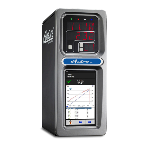
2.2 Front Console LED Display Indicator Light. Torque Display. (Always displays torque value) Secondary Display. Parameter Setting (PSet)/Job display and Increment/Decrement buttons. Toggle button Indicator Lights: Green LED: Indicates fastening cycle meets specified parameters. Red LED: Indicates fastening cycle rejected for exceeding high torque. -
Page 10: Initial Set Up
3 Initial Set Up Step 1 Connect tool cable to Tool Connector. Cable consists of a male pin set housed in a molded 19 pin connector with a polarizing notch. Align tool cable notch with t ool conn ect or notch on the controller and insert cable. Securely thread connector coupler to controller body. -
Page 11: Connecting To The Controller
3.1 Connecting to the Controller There are three ways to program/communicate with the controller: • Controller touch-screen console • System Port: (USB connection) Direct connection to controller. • Ethernet Port: Via direct connection or LAN. Touchscreen Console Controller functions and programming can be accessed directly through the touch-screen. 1. - Page 12 Connecting via The System Port directly to PC The following is an example using Window 7. Your screen may look different depending on the operating system. Windows USB Setup Step 1 Power on PC and controller, allow enough time for them to become fully operational. Step 2 Attach controller to PC using a USB 2.0 A-B cable.
- Page 13 Step 5 Go to ‘Network and Sharing Center’. Step 6 Go to ‘Change adapter settings’. Step 7 Find the Local Area Connection that is using the ‘USB Ethernet/RNDIS Gadget’ network. Right click this network and go to ‘Properties’. Step 8 In Properties window select ‘Internet Protocol Version 4’...
- Page 14 Step 9 In ‘Properties’, set the IP address to a static address. Type an IP address of 192.168.1.5 (Any address on the same subnet as the controller will work). Set subnet mask to 255.255.255.0 Step 10 To connect to the controller. Open a browser such as Chrome or Firefox.
- Page 15 Connecting using the Ethernet Port Directly or via LAN to PC Turn on the computer and make a physical connection by using a straight through Ethernet cable. Turn on controller. Verify the controller IP address in ‘Communication Interfaces’. Or press toggle button to verify the IP address.
-
Page 16: Quick Set Up (Default Psets From Tool)
3.2 Quick Set Up (Default PSets from Tool) On the Home Page press: to accept default PSet Parameters. This will generate three generic PSets for the tool connected to the controller. It will automatically use the 40%, 60%, and 80% of the rated maximum torque of the tool in a two- stage Torque Control Strategy (TC). -
Page 17: Run
4.1 Run The Run Screen is essentially the dashboard of the Gen IV controller and provides a look at real time information regarding rundowns. Indicates the current JOB. Indicates the current PSet you are operating in. Indicates accepted rundown. Indicates failed rundown. Displays Torque and Angle for current rundown. - Page 18 Time Overall Screen Click for curve detail. Click on arrow to change curve X axis. Choose Time in-cycle,Time Overall or Angle screen Angle Screen Page 18 of 125...
- Page 19 Run Screen (Job display information) Run Screen displays real time Job information. Large Screen Indicators and Audit information The large screen indicators are helpful in viewing real time results of the rundown from a distance. Accepted Failed Page 19 of 125...
-
Page 20: Pset
4.2 PSet Parameter Settings (PSets) control the fastening process. The following describes the different fastening stratagies and how to setup the basic PSet parameters necessary to perform a fastening. Up to 256 PSets are available. 4.2.1 Add New PSet n Home Page press the tab. - Page 21 On Add New PSet screen(below)enter appropriate values. PSet Number: Current PSet to be added. Torque Units: Unit of measure. In Cycle Torque: Threshold value at which tool is “In Cycle” and results from the Rundown will be reported. Cycle Complete Torque: Torque level that determines completion of a fastening cycle.
-
Page 22: Edit Pset
4.2.2 Edit PSet On Home page press: On the PSet screen (left) click on the desired PSet you would like to edit. Click on the Edit button to make changes in the Edit screen (right). If further Stage changes are needed click the Edit button again to enter Edit Stage screen (below). -
Page 23: Advanced Options
4.2.3 Advanced Options PSet Name: Add PSet name if desired (up to 10 characters). Thread Direction: Defines fastening direction (default is right hand). Re-hit/Reject Parameters: revents the fastening of an already tightened fastener. If enabled, tool will stop and the rundown will be aborted, if the angle of rotation between the Re-Hit Reference Torque and the In-Cycle Torque is less than the Re-Hit Angle Count. -
Page 24: Pset Stages
4.2.5 PSet Stages TC- Torque Control Stage Control strategy uses torque as the only control TC Stage parameter. The tool stops when Torque Target is reached. Rundown is considered to be successful (Accept) if the stage peak torque value falls within the range specified by the Torque High Limit and the Torque Torque Low Limit parameters. -
Page 25: Tc_Am Torque Control Angle Monitor Stage
TC_AM Torque Control Angle Monitor Stage Control strategy is convenient for detection of cross TC AM Stage threaded or stripped fasteners. Rundown is considered to be successful (Accept) if the stage peak torque value falls within range specified by Torque High Limit and Torque Low Limit and final angle value falls within the range specified by Angle High Limit and Angle Low Limit parameters. -
Page 26: Ac-Tm Angle Control Torque Monitor Stage
AC-TM Angle Control Torque Monitor Stage Control strategy in which the tool stops when Angle AC TM Stage Target is reached or Torque High Limit is exceeded. Rundown is considered to be successful (Accept) if l the stage peak torque value falls within range specified by torque upper and lower limits and final angle value Torque falls within the range specified by Angle High Limit and... -
Page 27: Tc_Ac Torque Control Angle Control Stage
TC_AC Torque Control Angle Control Stage Control strategy in which the tool stops if Target Torque TC AC Stage or Target Angle is reached, whichever happens first. Rundown is considered to be successful (Accept) if the stage peak torque value falls within range specified by Torque High Limit and Torque Low Limit and final angle Torque value falls within the range specified by Angle High Limit... -
Page 28: Delay Stage
Delay Stage Delay between Stages: Time the tool stops and waits before proceeding to the next stage. Default is 0.2 (sec). Time Delay (sec): Total time in seconds the tool stops and waits before proceeding to the next stage. Ergo Stop Stage Ramps cut-off power when fastening achieves Target Torque or Target Angle value. -
Page 29: Unfasten Stage
Unfasten Stage This feature is a specific “backoff” stage used, for Unfasten Stage example, in a Rundown-Backoff or Rundown-Backoff- Rundown configuration. NOTE: In this stage, the tool Angle (-) always runs opposite of the thread direction. Low Limit Angle High: Maximum allowed angle rotation in degrees. High Limit Angle Target: Degrees of rotation the tool will backoff in reverse. -
Page 30: Ac_Ta Angle Control Torque Averaging Stage
AC_TA Angle Control Torque Averaging Stage Control Strategy is helpful in applications where the rotational resistance measured can produce a pass or fail reading. This will help in gauging rolling resistance of a given part and aid in detecting latent failures in rotating assemblies. -
Page 31: Sync Stage
Sync Stage Set synchronization point between stages for spindle networks. All spindles will wait on this stage until all controllers are ready to proceed to the next stage. Stage Timeout (sec): Total time in seconds the controller will wait in this stage before timing out and aborting the rundown. -
Page 32: Ac_Tcomp Angle Control Torque Compensation Stage
AC_TCOMP Angle Control Torque Compensation Stage The ‘Angle Control Torque Compensation Strategy’ is used to compensate for the prevailing torque of the fastener. The prevailing torque can be averaged over a set angle and the torque will be adjusted by the average torque measured, allowing it’s effect to be removed from the final torque applied to the fastener. - Page 33 AC_TCOMP Angle Control Torque Compensation Stage Continued Removing the Prevailing Torque The strategy will measure the average prevailing torque over a given angle. At the completion of the stage the torque transducer will have its tare value adjusted by the average torque. Removing the prevailing torque readings for the remainder of the fastening cycle.
-
Page 34: Yield Control
Joint Rate parameters have default settings of 5 samples every 20 degrees. This resolution can be adjusted if needed. See previous stage types for Torque, Angle, Speed, and Time detail For more details please go to www.AIMCO-global.com Resources/Manuals/Yield Control Page 34 of 125... -
Page 35: Multistage Rundown Evaluation And Reporting
4.2.6 Multistage Rundown Evaluation and Reporting If a rundown cycle completes, or is terminated early while in or after the final audit stage of • the PSet: The overall evaluation of the rundown will be determined using the torque and angle limits set in the final audit stage. - Page 36 Torque Averaging Stages (AC_TA and AC_TCOMP) reporting exception: • If a torque averaging stage fails to complete, or is the final audit stage, and the peak torque is less than the high torque limit, the final torque reported will be the torque average during that stage.
-
Page 37: Multiple Stage Rundown Examples
4.2.7 Multiple Stage Rundown Examples EXAMPLE: Two-stage rundown with downshift This example shows a typical two stage rundown with a higher first stage free speed and slower down shift speed to minimize overshooting of the target torque. EXAMPLE: Three stage rundown with unfasten on the last stage. (Rundown Back-off) This example shows a typical three stage rundown with a back-off stage at the end of the rundown. - Page 38 EXAMPLE: Four stage rundown with an unfasten stage in the middle. (Rundown back off Rundown) NOTE: The peak torque was reset at the start of the fastening stage. The torque reported was from the final stage. Page 38 of 125...
-
Page 39: Job
4.3 Job A Job is a collection of PSets which can be run when performing multiple fastening operations on a single application. Jobs provide: Error proofing. • Logical grouping of PSets. • • Fastening order. Job status. • Click to Enable/Disable Job function. 4.3.1 Add New Job To add a new Job press on the Home Page. -
Page 40: Advanced Options
After appropriate values are entered, press to go to Add New Job Sequence screen. PSet Number: Choose any current PSet already configured in controller. Action: • None: Will stay in current sequence. • Next: will advance to next sequence set up after count is reached. - Page 41 Jobs “ Enabled” display and button function: Secondary Display. PSet/Job display and Increment/Decrement buttons. Toggle button: PSet/Job functions. Increment and Decrement buttons change the job sequence. The pset number will • change and job sequence number on secondary display will change if jobs are enabled. Holding the toggle button will display will display the Job number, while pressing •...
-
Page 42: Results
4.4 Results This screen provides a history of rundowns performed. Information such as ID Number, Time Stamp, Parameter Set#, Accept /Reject status, and Torque and Angle are recorded for each rundown. Deletes individual rundowns by clicking on them separately and deleting them in the next screen or deleting all rundowns by clicking on the icon at the bottom of Results page. -
Page 43: Saving Rundown(S)
Rundown file is tab separated variables and can be viewed using Excel. The raw data can now be imported to Excel to build graphs, charts etc. Contact AIMCO Technical Service for pre- made Torque and Angle Templates. INDIVIDUAL RUNDOWNS... -
Page 44: Controller
4.5 Controller The controller menu is where all of the settings for the Gen IV controller are configured. All of the different configuration capabilities are explained below. 4.5.1 Tool Setup In this screen user can enable/disable various tool functions. 4.5.1.1 Lock On Reject When enabled this prevents tool from starting a new rundown if the result of the last rundown was a reject. -
Page 45: Buzzer
MFB: Pressing MFB button on tool (regardless of MFB configuration). Unlock Torque: If Unlock Mode is set to “Reverse and Unlock Torque”, this torque value must be exceeded when tool is in the disassembly direction in order to unlock tool. 4.5.1.2 Buzzer Buzzer Enable: When enabled, the Buzzer will beep when a rundown is rejected. -
Page 46: Mfb (Multi-Function Button)
4.5.1.5 MFB (Multi-Function Button) The MFB Mode configures the multiple function button for handheld AcraDyne tools. The button can be configured to operate in any of the following modes: TAP MODE: Actions will commence if MFB is held less than hold time. -
Page 47: Disassembly
4.5.1.6 Disassembly Timeout (sec): Total amount of time, in seconds, after throttle is depressed that tool will operate. Max Speed (RPM): Maximum speed of the Output spindle. Acceleration: Rate at which tool is set to ramp up to maximum RPM. Report Disassembly: If enabled, disassembly events will be reported and logged. -
Page 48: Tubenut
4.5.1.7 Tubenut Tubenut Homing Parameters: Homing Configuration: Two options are available- • Release and Repress: Socket will return Home on release and repress of main lever. NOTE: If the main lever is released while homing in this configuration the tool will stop and will continue to Home once the lever is repressed. -
Page 49: I/O
4.5.2 I/O 4.5.2.1 Physical I/O Assign functionality to 24V Input and Output pins. Shows the “live state” of each Input and Output. Functions shown in screen shot are default settings. To change these assignments, click on any I/O state to enter Output/Input Configuration screen (below). -
Page 50: Anybus/ Modbus Tcp/Ethernet Ip Inputs
4.5.2.3 Anybus/ Modbus TCP/Ethernet IP Inputs These types of communication are useful for data communication between controller and PLC’s. It is an effective, quick way for the data transfer of short data packages. Press to enter Input Configuration Screen (below) Element Type: Choose from Byte, Int16 or Int32. -
Page 51: Anybus/Modbus Tcp/Ethernet Ip Outputs
4.5.2.4 Anybus/Modbus TCP/Ethernet IP Outputs Press to enter Output Configuration Screen (below) Element Type: Choose from Byte, Int16 or Int32. Element: Shows Element # being configured. Bit: Enter Bit # Polarity: Select Normally Open or Normally Closed Outputs. Mode: Normal - Output signal sent. Timed signal sent (Time entered in seconds) Flash - signal sent (Time entered in... -
Page 52: Communication Interfaces
4.5.3 Communication Interfaces 4.5.3.1 Ethernet/Second Ethernet • IP Address: IP address of controller’s Ethernet port. • Subnet Mask: Subnet mask of the controller. • Gateway: Gateway is the IP address of the gateway computer that provides access beyond the local network. NOTE: Consult your local System Administrator to connect the controller to your Network and assign IP addresses. -
Page 53: Serial
4.5.3.3 Serial Port Mode: The following modes are available: • Serial Output: A serial data string will be Output in the following format after each rundown: # P 1 BB TTT.T AAAA 0000 0000 J • (Notice the decimal point next to the least significant T) P: Parameter set (“1”... - Page 54 Serial Output Format Options Standard Output Format: • O P HHHHH LLLLL TTTTT P HHHHH LLLLL AAAAA CR CR NULL* O: Overall Pass/Fail ‘P’ = Pass, ‘F’ = Fail • P: Torque Pass/Fail ‘P’ = Pass, ‘F’ = Fail •...
- Page 55 ‘P’ = Pass, ‘F’ = Fail • HHHHH: Angle High Limit Degrees • LLLLL: Angle Low Limit Degrees • AAAAA: Angle Result Degrees • 1: PSet PSet(‘1’ – ‘9’) for PSets 1-9, (‘A’ – ‘Z’) for PSets 10-35 •...
- Page 56 P: Torque Pass/Fail ‘P’ = Pass, ‘F’ = Fail • HHHHH: Torque High Limit Units selected in the PSet X10 • LLLLL: Torque Low Limit Units selected in the PSet X10 • TTTTT: Torque Result Units selected in the PSet X10 •...
-
Page 57: Anybus
Pset Changed String Format: PSet Changed String Format: • %CAN 8 A NAC% %CAN 4 B NAC% NULL* %CAN: Message Start A: Previous PSet PSet(‘1’ – ‘9’) for PSets 1-9, (‘A’ – ‘Z’) for PSets 10-35 • NAC% ... -
Page 58: Spindle Usb Port
4.5.3.5 Spindle USB Port This can be used to set up a 2 spindle network through the USB port 4.5.4 Front Panel Buttons Enable/ Disable front panel buttons on controller console Page 58 of 125... -
Page 59: Power Up
4.5.5 Power Up • Allows user several “Job” choices upon controller Power • Power Up Job Number: Controller will power up on the job # selected. When “Last job” is selected, controller will power up on last job selected prior to being Powered Down. - Page 60 Step 2: Enter appropriate information on Barcode ID Configuration Screen. Identifier Mask: The Mask is a string used to compare the received barcode against. The received barcode must be at least as long in length as the Mask. The Mask can also contain “don’t care”...
-
Page 61: Set Time
4.5.7 Set Time Set time and date. If connected to a PC, use PC Time to set controller time. 4.5.8 Remote Connections Sets number of remote browser connections to controller. Page 61 of 125... -
Page 62: Master Spindle Setup
4.5.9 Master Spindle Setup Several Gen IV controllers can be linked together via an Ethernet connection to create a multi- spindle network. Operations requiring multiple fasteners to be inserted simultaneously or in a synchronized fashion is possible with this setup. Up to 10 tools can be operated from one master controller. - Page 63 Software Steps to enable the multi-spindle network: 1. Configure the IP address of each spindle: Ensure that they are all on the same subnet. 2. Set each controller to be controlled from the master controller: Go to ControllerTool SetupStart Input and set the input source to ‘Start from Master Tool’. 3.
- Page 64 Spindle IP Addresses: The number of spindles listed depends on the number of spindles enabled. Add the IP addresses of the slave spindles to add them to the spindle network. PSets: Synchronizing Stages When setting up a PSet, the Sync stage is available to synchronize spindle rundowns.
-
Page 65: Languages
4.5.10 Languages Select from: English Chinese Japanese Korean Spanish 4.6 Tool Page 65 of 125... -
Page 66: Tool Setup
4.6.1 Tool Setup Allows user to make changes to Tool Setup. Model Number: Tool model number of tool connected to controller. Tool ID: Serial Number of current tool connected to controller. Cycle Count: Total number of cycles since last reset. Multiplier: Configures tool to include gearing added to the base model. -
Page 67: Button Calibration
4.6.3 Button Calibration After a tool has been worked on, it is possible the relationship between hall sensors and magnet have changed. Using the ‘Tool Button Calibration’ screen calibrates the field between the two. Test throttle and MFB (Multi-Function Button), send values to Tool ID board in this screen. -
Page 68: Torque Calibration Routine
4.6.5 Torque Calibration Routine Used to calibrate tool using a Master Transducer. The following are steps to calibrate tool. 1. Press the “Start Calibration” button. 2. Run Tool to Final Torque. 3. Enter external transducer (Master) value in Measured Torque box. -
Page 69: Tid Parameters
4.6.7 TID Parameters Used by factory to load Tool ID parameters into tool. 4.6.8 TID Memory Allows a Qualified Service Technician to view or edit Tool Page 69 of 125... -
Page 70: Accessories
For more specific instruction contact: AIMCO Technical Service Toll Free 1-800-852-1368 or go to http://www.aimco- global.com/Data/Sites/1/manuals/gen-iv-controller-smart- arm-manual.pdf. 4.8 Diagnostics The Diagnostics menu contains all pertinent information regarding unusual behavior of the system. -
Page 71: Controller Overview
4.8.1 Controller Overview • Model Number: Model Number of the controller. • Serial Number: Serial Number of the controller. • Type: Type of controller- IEC – Intelligent Electric Controller IEC4W – Intelligent Electric Controller 4 Mobile Application: Current Application software version. Firmware: Current Firmware software version. -
Page 72: Tool Overview
4.8.3 Tool Overview This “read only” screen gives an overview of the tool connected to the controller. The information is stored in the memory on the Tool ID board (TID). Model Number: Model number of tool connected • to controller. Serial Number: Serial number of tool connected to •... -
Page 73: Live Tool
4.8.4 Live Tool Shows a live view of tool transducer in volts. Voltage will be approximately 2.0 volts (± 0.005 Vdc) when tool is at rest and torque is zero (verify the voltage is within the green zone in the graph). -
Page 74: System Status
4.8.7 System Status 4.9 Login When a password is required it can be entered in this screen. Three levels of access to the controller are available: Operator Run/Login screens available. • • Technician Run/PSet/Job/Diagnostics and Login screens available. • Admimistrator All screens available. Page 74 of 125... -
Page 75: Advanced
4.10 Advanced The ‘Advanced’ menu handles complex settings within the controller. Detailed descriptions are given below 4.10.1 Login Setup This screen allows the user to select the default Login level upon controller start up. • Operator • Technician • Administrator Page 75 of 125... -
Page 76: Results Archive
4.10.2 Results Archive Approximately one million rundowns can be stored. Twenty files with approximately 50,000 rundowns are maintained at a time. The user can, at any time, save the runs to either a USB stick or to the Web as a USV file imported directly into an Excel spreadsheet. Using the touchscreen console you can select multiple files to save. -
Page 77: Export Controller
Select the settings to be changed by pressing changing it to Configuration: This includes all settings of the controller except I/O, Master Spindle, Rundowns, PSets or Jobs. Operations: This includes PSets and Jobs. I/O: This includes I/O settings for the local I/O, Anybus, Modbus, and EtherNet/IP. -
Page 78: Update Controller
NOTE: Updated firmware versions will typically be sent via email zip file. Always save PSet and IP address information before upgrading controller. Upgrading the AIMCO Gen IV Controller Using the TouchScreen or a System Port browser session, navigate to the ‘Advanced’ menu. -
Page 79: Backup Restore
4.10.6 Backup Restore The Backup function allows the user to create an image of the controller software/firmware including all Configurations, Operations, I/O, and Spindle settings. This is used to create a point in which the controller can restore to if the need arises. In that case, the Restore function would be used. -
Page 80: Restore Factory Defaults
4.10.7 Restore Factory Defaults This allows the user to reset the controller’s parameters to factory settings 1. From the Home screen, navigate to AdvancedRestore Factory Defaults. 2. Select the settings to be changed and accept Operations: This includes PSets and Jobs. •... -
Page 81: Calibrate Touch Screen
4.10.8 Calibrate Touch Screen Calibrate Touch Screen Custom and Factory default calibration are available on the controller console. 1. From the Home screen, navigate to Advanced Calibrate Touch Screen. 2. Press to disable the tool. 3. Select the settings to be changed by pressing changing it 4. -
Page 82: Barcode Reader Details
5 Barcode Reader Details The Gen IV controller supports the following barcode reader functionality: Support up to four identifiers. • Each rundown result can be associated with up to four identifiers. • Identifier(s) can be used to select a parameter set or a job. •... - Page 83 Action Action can be one of the following: None • Select PS#1-256 • Select Job#1-20 • Reset ID The “Reset ID” has the ability to reset other identifiers (ID#1-4) when barcode is received Examples: Operator Scans When a vehicle enters the station, the operator scans the VIN. The controller selects the correct job number and enables the tool.
- Page 84 Examples This is what the ‘Operator Scans’ example looks like once set up in 4.5.8 Barcode Configuration Screen. Airbag Install The customer wants to track the serial number of each airbag being installed, as well as, the operator installing it. When the operator reports to the station, they will scan their employee ID. When the vehicle comes into the station, the operator scans the VIN of the vehicle and the serial number of the airbag.
-
Page 85: Glossary Of Terms
6 Glossary of Terms This setting controls how quickly the tool comes to programmed Acceleration RPM. The value is stated in thousand(k) revolutions per minute (RPM) per second(s). Default setting is 10 which means that at the start of the rundown or stage, the tool will reach 10,000 RPMs in a one second period of time. - Page 86 When peak torque recorded exceeds the High Torque, the High Torque fastening cycle is recorded as a reject for High Torque, the High Torque light (flashing red) illuminates and fastening cycle is given an overall status of NOK. A Job is a collection of Psets or Multi-stages, which are useful when performing several multiple fastening operations, each with different requirements.
-
Page 87: Icons Defined
7 Icons Defined ICON DESCRIPTION FUNCTION WHERE USED Home Navigation Navigate to the main menu All screens except Button (“HOME”) screen. for edit screens. Run Navigation Navigate to the Run Screen. All screens except Button for edit screens. Run Screen Select Switch between the Run Screen Buttons... -
Page 88: Stop Codes
7.1 Stop Codes If a Stop condition is detected that prevents the tool from running, a code will appear on the LED display. Any active stop conditions are also displayed on the RUN screen. CODE ICON Description Stopped or Disabled from Physical 24 volt IO input ABUS Stopped or Disabled from ANYBUS MODB... -
Page 89: Error Codes
XML Disconnected Stop from XML XML Max Rejects Exceeded Controller Fault - Error has been detected. See fault code list for details 8 Error Codes If an error condition is detected that prevents the tool from running, a fault code will appear on the LED display. - Page 90 FH25 -15vdc out of -15 Volt bus voltage out of Faulty power supply or wiring • tolerance range Faulty Controller main board • or other Controller electronics Faulty tool cable • Faulty tool electronics or • wiring FH32 Processor Fault RTOS processor not Faulty mainboard electronics •...
- Page 91 IEC (AcraDyne DC Tool) Specific Fault Codes CODE Fault Type Description Possible Causes FT01 Tool not connected Tool communication Tool not connected • timeout Faulty tool cable • Faulty tool electronics or • wiring FT02 Invalid TID Tool parameter file not Corrupt tool ID memory •...
- Page 92 Faulty drive • FD14 Drive Fault HW Drive reporting fault via Tool not connected • IO signal Faulty tool cable • Faulty tool motor • Application exceeds • capability of drive Faulty drive • FD15 Drive Vbus high Drives DC bus voltage AC supply power exceeds •...
-
Page 93: Dual Lever Tools Requiring Two Handed Operation
9 Dual Lever Tools Requiring Two Handed Operation Two Handed Functionality • Tool will not run unless both switches are pressed within one second of each other. • If the one second timer times out, both switches must be released to reset the timer. •... -
Page 94: 24 Volt I/O
10 24 Volt I/O Port Pinout and Diagrams A I/O wiring adapter kit is available (Part #27348) from AIMCO to make connection to I/O port on the controller easier. Contact your AIMCO Sales Representative for ordering information. Toll Free: 1-800-852-1368. - Page 95 Importing IO on an iEC4 These instructions detail how to import IO into an iEC4 controller via the system port to modify the Anybus outputs. 1. Power on the controller 2. Insert the USB stick into a USB port 3. Connect to the controller via system port and web browser (default address 192.168.1.4) 4.
- Page 96 9. Verify the Anybus outputs. a. Navigate to Controller->IO- >Anybus Outputs b. Click on the first row of element #1 and verify it is set as ‘Running Job Number’, Bit 0, Bits 8, Start at 0. c. Click on element #4 and verify it is set as “Torque (x100)”, Bit 0, Bits 16...
-
Page 97: Assignable Io Details
11 Assignable IO Details Introduction The Gen IV controller supports assignable I/O. Buses The controller is divided up into buses. Each bus has a set of inputs and a set of outputs. Currently the controller supports the following buses. Bus Number Physical I/O Fieldbus (Anybus module) I/O Modbus TCP... - Page 98 √ √ √ √ √ √ √ Increment Batch √ √ √ √ √ √ √ √ √ Click Wrench √ √ √ √ √ √ √ √ √ Bypass Stops √ √ √ √ √ √ √ √ √ √...
- Page 99 The “Stop” assignment will stop the tool if it is running and prevent it from being started. Reverse Supported Feature Element Polarity 0-31 N.O./N.C. Width Offset √ √ √ √ The “Reverse” will put the controller in disassembly mode while the input is active. Disable Supported Feature Element...
- Page 100 The “Select Job Sequence” input will select the job sequence number according to the input value. Uses the width parameter limit the width of the input bits read. The minimum width is 1 and the maximum is 8. After the input is read the offset parameter will be added to the value do get the actual job sequence number.
- Page 101 √ √ √ √ The “Set Date/Time” assignment will set the date and time of the controller. The width can be set from 1 to 32 bits but should always be set to 32 to get the correct results. The input value will be read as the number of seconds since 00:00:00 January 1, 1970 (POSIX time or Epoch time).
- Page 102 0-31 N.O./N.C. √ √ √ √ The “Increment Batch” assignment will insert a manual rundown into the current sequence of the current JOB. This will cause the JOB count to increment by one. Click Wrench Supported Feature Element Polarity 0-31 N.O./N.C.
- Page 103 √ √ √ √ √ √ √ √ √ √ √ √ √ √ √ √ √ √ √ √ Torque Ok √ √ √ √ √ √ √ √ √ √ Torque √ √ √ √ √ √ √ √...
- Page 104 External √ √ √ √ √ √ √ √ √ √ √ Controlled Tool In √ √ √ √ √ √ Tool In √ √ √ √ √ √ Torque √ √ √ √ √ √ √ √ √ Torque √...
- Page 105 Assignments active Output state IGURE ORMAL Timed In the “Timed” mode the output will come on when the assignments state goes active and go off based on the time value or the assignment state going inactive (while still observing the polarity setting). Assignments active Output state Time...
- Page 106 Width and Offset For multiple bit outputs (for example “Running PSet Number”) the width variable defines the number of bits the assignment will output. This allows the output size to be restricted to a few bits saving space for other assignments. The offset variable allows a fixed value to be added to the value before it is output.
- Page 107 Supported Feature Element Polarity Mode Time Width Offset Input Input Input 0-32 N.O., Normal, Element N.C. Timed, Flash √ √ √ √ √ The “Torque Nok” output assignment will go active at the completion of a fastening that has an unacceptable torque value.
- Page 108 The “Angle Nok” output assignment will go active at the completion of a fastening that has an unacceptable angle results. It will go inactive when the next fastening is started (the torque exceeds the threshold value) or a Job reset. Low Angle Supported Feature Element...
- Page 109 √ √ √ √ √ The “Fastening Aborted” output assignment will go active at the completion of a fastening that was aborted by the system. It will go inactive when the next fastening is started (the torque exceeds the threshold value) or a Job reset. Fastening Stopped Supported Feature Element...
- Page 110 Normal, Timed, Flash √ √ √ √ √ The “Tool Start Switch” output assignment will reflect the state of the tools start lever. Tool Push to Start Switch Supported Feature Element Polarity Mode Time Width Offset Input Input Input 0-32 N.O., Normal, Element...
- Page 111 Supported Feature Element Polarity Mode Time Width Offset Input Input Input 0-32 N.O., Normal, Element N.C. Timed, Flash √ √ √ √ √ The “ToolsNet Connected” output assignment will be active if the controller has an active connection to a ToolsNet server. Open Protocol Connected Supported Feature Element...
- Page 112 Normal, Timed, Flash √ √ √ √ √ √ The “External Controlled” output assignment will reflect the state of an input. Use the “Input Bus, “Input Element”, and “Input Bit” to specify the input to reflect. Tool In CCW Supported Feature Element Polarity Mode...
- Page 113 Element Polarity Mode Time Width Offset Input Input Input 0-32 N.O., Normal, Element N.C. Timed, Flash √ √ √ √ The “Torque (x100)” output assignment will output the final torque value of the most recent rundown. The value will be cleared to 0 at the start of a new fastening cycle or a Job reset. At the end of the fastening cycle the final torque will be multiplied by 100, truncated to an integer and output.
- Page 114 Supported Feature Element Polarity Mode Time Width Offset Input Input Input 0-32 N.O., Normal, Element N.C. Timed, Flash √ √ √ √ √ The “Spindle NOk” output assignment will go active at the completion of multi-spindle fastening if one or more of the spindles have an NOK.
-
Page 115: Controller Supported Mids
Pulses High Supported Feature Element Polarity Mode Time Width Offset Input Input Input 0-32 N.O., Normal, Element N.C. Timed, Flash √ √ √ √ √ The “Pulses High” output assignment will go active at the completion of a fastening that has an pulse count that exceeds the high limit. - Page 116 37 Job info unsubscribe 38 Select Job 39 Job restart 40 Tool data upload request 41 Tool data upload reply 42 Disable tool 43 Enable tool 50 Vehicle ID number download request 51 Vehicle ID number subscribe 52 Vehicle ID number 53 Vehicle ID number acknowledge 54 Vehicle ID number unsubscribe 60 Last tightening result data subscribe...
- Page 117 157 Reset all Identifiers 200 Set external controlled relays Only supports 0 (off) and 1 (on) 210 Status external monitored inputs subscribe 211 Status external monitored inputs 212 Status external monitored inputs acknowledge 213 Status external monitored inputs unsubscribe 214 IO device status request 215 IO device status reply 216 Relay function subscribe See supported relay functions below.
-
Page 118: Dimensions
12 Dimensions 13 Specifications Mechanical: Dimensions: Width: 6.25 in 159 mm Height: 15.75 in 400 mm Depth: 12.5 in 316 mm Weight: 15.65 lbs 7.1 kg Operating Conditions: Temperature: 32 to 122 ᵒF (0 to50 ᵒC) Humidity: Non-condensing Ingress IP20 Protection: Electrical: AC Power Source:... -
Page 119: Tubenut Tool Setup Details
230 VAC, 1Φ, 50/60 Hz. 10 - 15A dedicated service (Recommended for high duty cycle applications) Standards: Safety Compliance: EC Machinery Directive 2006/42/EC EC Low Voltage Directive 2006/95/EC EN 12100-1; EN 12100-12 Safety of Machinery EN 60745-1; EN 60745-2-2 Hand-held motor operated tools EC Directive of Electromagnetic Compatibility 2004/108/EC EN 61000-6-4;... -
Page 120: Controller Parameters Affecting Tubenut Homing
Gradually increase the value for the Home Detection Torque until tool reliably returns to the • Home position. When a good value for the Home Detection Torque is found, if the tool is bouncing back to a • partially closed position after hitting the Home stop, gradually increase the value for the Hold at Home Torque until bounce back is eliminated. -
Page 121: Setting The Tool's Tubenut Obstruction Detection
Units: lbf-in TID memory location: 53 14.5.2 Setting the Tool’s Tubenut Obstruction Detection Parameters Set value for the obstruction torque just high enough so tool will reliably overcome gear friction • and make it past the obstruction checking zone. Check torque of the stop on obstruction feature by measuring the actual “pinch” torque the •... -
Page 122: Trouble Shooting
15 Trouble Shooting Issue: SD Card initializing Soultion: The rear SD card can be used to easily move the software, firmware, configuration, and rundowns to a new controller in the event of hardware failure. This allows the controller to be replaced with a new unit while retaining all the rundown information and configuration settings. - Page 123 Step 3 Right click on it and select Update Driver Software. When prompted, choose Browse my computer for driver software to search for device driver software. Step 4 Browse for driver software on your computer will come up. Select Let me pick from a list of device drivers on my computer.
-
Page 124: Aimco Warranty
(1) year* from date of delivery. Under the terms of this warranty, AIMCO agrees, without charge, to repair or replace, at its option and Ex-Works (EXW) its authorized service centers, any product or accessory warranted hereunder proving to AIMCO's satisfaction to be defective as a result of defective workmanship or material. - Page 125 The warranty provision with respect to each such product may be amended by AIMCO from time to time in its sole discretion. The liability of AIMCO hereunder shall be limited to replacing or repairing, at its option, any defective products which are returned freight pre-paid to AIMCO or, at AIMCO's option, refunding the purchase price of such products.
Need help?
Do you have a question about the AcraDyne Gen IV and is the answer not in the manual?
Questions and answers