Table of Contents
Advertisement
Quick Links
WARNING: If the information in these
instructions is not followed exactly, a fire
or explosion may result in causing
property damage, personal injury, or loss
of life.
Do not store or use gasoline or other
flammable vapors or liquids in the
vicinity of this or any other appliance.
If you smell gas, please:
-
Do not try to light any appliance
-
Do not touch any electrical
switch; do not use any phone in
your building.
-
Immediately call your gas
supplier from a neighbor's
phone. Follow the gas supplier's
instructions.
-
If you cannot reach your gas
supplier, call the fire department.
A qualified installer, service agency, or
local gas supplier must perform
installation and service.
INSTALLER: Leave this manual with the appliance.
CONSUMER: Retain this manual for future reference.
Installation and service of this appliance must be performed by qualified NFI certified technician, or a certified
and trained Flare Fireplaces dealer.
Massachusetts: The piping and final gas connection must be performed by a licensed plumber or gas fitter in
the state of Massachusetts. Also, see local code for carbon monoxide requirements.
Flare Fireplaces Large Installation Manual – SIT ProFlame II
[Double, Left, and Right Corner, Front Facing, Large Direct Vent Models 120"- 400"] v18.4
DANGER
A barrier designed to reduce the risk of burns from the hot
viewing glass is provided with this appliance and must be
installed for the protection of children and other at-risk
individuals.
NOTICE
HOT GLASS WILL CAUSE
BURNS.
DO NOT TOUCH GLASS UNTIL
COOLED
NEVER ALLOW CHILDREN TO
TOUCH GLASS
Flare requires installation be performed by
an NFI certified installer, or an authorized
Flare Dealer Tech who has been trained to
professionally install the fireplace.
Installations that do not follow this
instruction will not be covered by warranty
or service.
Advertisement
Table of Contents

Related Manuals for Flare Fireplaces Large Flare Front 120


Summary of Contents for Flare Fireplaces Large Flare Front 120
- Page 1 Massachusetts: The piping and final gas connection must be performed by a licensed plumber or gas fitter in the state of Massachusetts. Also, see local code for carbon monoxide requirements. Flare Fireplaces Large Installation Manual – SIT ProFlame II [Double, Left, and Right Corner, Front Facing, Large Direct Vent Models 120”- 400”] v18.4...
-
Page 2: Table Of Contents
TABLE OF CONTENTS SAFETY INFORMATION AND WARNINGS............................... 7 MANUAL MODEL LIST AND INFORMATION ............................11 REMOTE CONTROL OPERATION ................................13 IFC PROFLAME II REMOTE BUTTONS ............................13 REMOTE CONTROL SPECIFICATION ............................. 14 TEMPERATURE INDICATION DISPLAY ............................14 TURNING THE SYSTEM ON AND OFF USING THE REMOTE CONTROL ................... 15 REMOTE FLAME MODULATION.............................. - Page 3 STEP 9 ......................................27 STEP 10 ....................................... 27 FIREPLACE GLASS INSTALLATION ................................ 28 WHERE DOES EACH GLASS PANEL GO? ............................28 INSTALLING YOUR BLACK REFLECTIVE BACK ............................29 STEP 1: ......................................29 STEP 2 ......................................29 REMOVING THE MAGNETIC FILLERS AND INNER TRIM BRACKETS....................... 30 STEP 1: ......................................
- Page 4 STEP 4 ......................................47 STEP 5 ......................................47 STEP 6 ......................................47 STEP 7 ......................................47 RGB LED ELECTRICAL DIAGRAM ..............................48 LED CONTROLLER AND REMOTE ..............................49 MODE SELECTION AND REMOTE ..............................50 CODE MATCHING (GEN 1 REMOTE): PAIRING YOUR GEN 1 RGB LED REMOTE ................51 CODE CLEARING (GEN 1 REMOTE): UNPAIRING YOUR GEN 1 RGB LED REMOTE .................
- Page 5 ACCEPTABLE INLET GAS PRESSURE TABLE ........................... 70 GAS VALVE OVERVIEW ................................... 71 USING A REDUCER TO DE-RATE YOUR FIREPLACE ........................... 72 ADDING THE FLARE DE-RATING REDUCER............................73 STEP 1 ......................................73 STEP 2 ......................................73 ORIFICE SIZE ....................................74 GAS VALVE ACCESS DOOR ................................74 MANUAL GAS SHUT-OFF................................
- Page 6 SHADOW LINE .................................... 99 TOP SLOT ....................................99 KEEPING THE WALL ABOVE YOUR FIREPLACE AS COOL AS POSSIBLE ....................99 AIR INTAKE SIZING ..................................100 EXAMPLES OF AIR INTAKES ................................101 FLOATING HEARTH ................................... 101 TOE-KICK REVEAL ..................................101 LEFT/RIGHT/BOTTOM SLOTS ..............................101 SLOT DIFFUSER –...
-
Page 7: Safety Information And Warnings
SAFETY INFORMATION AND WARNINGS WARNING! If the information in these instructions is not followed exactly, a fire or explosion may result causing property damage, personal injury, or loss of life. A qualified installer, service agency or the supplier must perform installation and services. - Page 8 This appliance must be electrically wired and grounded in accordance with local codes, or in the absence of local codes, with National Electric Code ANSI/NFPA 70 – latest edition or the Canadian Electric Code CSA C22.1 A 110-120V AC Circuit for this product must be protected with ground-fault circuit-interrupter protection, in compliance with the applicable electrical codes, when it is installed in locations such as bathrooms or near sinks.
- Page 9 Turn off the gas before servicing this fireplace. It is recommended that a qualified service technician perform a fireplace check-up at the beginning of each heating season. This vented gas fireplace heater is not for use with air filters. WARNING: Improper installation, adjustment, alteration, service, or maintenance can cause injury or property damage.
- Page 10 Certification Information: CSA File # 263124 CSA/ANSI Z21.88-2019 • CSA 2.33-2019- Vented Gas Fireplace Heaters CSA CLASSES: CLASS 2901 84 / CLASS 2901 04 All fireplaces are rated for commercial and residential use. The CSA Mark The Canadian Standards Association (CSA) is a nonprofit association serving business, industry, government and consumers in Canada and the global marketplace.
-
Page 11: Manual Model List And Information
The Following manual should be used for the following Flare Fireplaces Models: • Large Flare Front 120, 140, 160, 180 - 400 “– 16” (R), 24” (H) • Large Flare Corner Right & Left 120, 140, 160, 180 - 400” – 16” (R), 24” (H) - Page 12 The Flare Fireplaces Large units are designed to be as big as 400" long. The Fireplace is designed and shipped in sections to allow easy installation and transformation. For example, a Flare 140 is shipped from two 70" section.
-
Page 13: Remote Control Operation
REMOTE CONTROL OPERATION Below is the SIT ProFlame II remote control operation for the Large Flare Fireplaces. IFC PROFLAME II REMOTE BUTTONS - Main ON/OFF switch - Main Burner Flame Modulation 6 Levels - Continuous or intermittent pilot mode (Intermittent is default) - Thermostat or smart thermostat functions. -
Page 14: Remote Control Specification
REMOTE CONTROL SPECIFICATION - Need 4.5 voltage supply. - 0-50 °C ambient temperature rating. - 315 MHz radio frequency. TEMPERATURE INDICATION DISPLAY - When the system is turned off the LCD screen will display the current room temperature in Fahrenheit (°F) or in Celsius (°C.) - To change from Fahrenheit (°F) to Celsius (°C) or vice versa press the thermostat key and the mode key at the same time. -
Page 15: Turning The System On And Off Using The Remote Control
TURNING THE SYSTEM ON AND OFF USING THE REMOTE CONTROL - With the system OFF, press the ON/OFF Remote Key. The remote LCD will then show other icons. At that time, the module will activate the appliance and a single beep from the receiver will confirm reception command from the remote - When the system is ON, press the ON/OFF remote key, the remote LCD will show the room temperature icon, at the same time the module will shut off the appliance. -
Page 16: Thermostatic Mode
LCD. NOTE: When Smart Thermostatic mode is activated the flame level modulation is not activated. FAN SPEED CONTROL This feature is not available on Flare Fireplaces. -
Page 17: Key Lock
KEY LOCK To avoid unsupervised operation of the remote control this feature has been created. To activate this feature, press the mode and up arrow at the same time. A lock icon will appear in the LCD screen. To deactivate this feature, press the mode and up arrow at the same time. -
Page 18: Pairing The Remote With The Fireplace Receiver
PAIRING THE REMOTE WITH THE FIREPLACE RECEIVER Your remote will come paired with the fireplace receiver to allow for operation out of the box. In the event of a remote or receiver replacement, use the following procedure to pair the remote with the receiver: INITIALIZING THE SYSTEM FOR THE FIRST TIME - Install 3 AAA type batteries in the remote battery bay located on the remote back. -
Page 19: Ignition Sequence
IGNITION SEQUENCE Starting from OFF, press the remote power button. Four seconds after it is pushed the SIT module will send spark to the pilot hood, and spark for 60 seconds. If there is no flame ignition during the first ignition sequence, the SIT module will stop sparking for approximately 35 seconds and then begin sparking again. -
Page 20: Fireplace Media
FIREPLACE MEDIA Every Flare fireplace can be set up with approved glass, stone, or wood media. Quantities are determined by the size of the fireplace and type of media chosen within that fireplace (Click Here For Media Calculation Guide). Mixing of media types (i.e., glass and stones together) is acceptable if the quantities are adjusted to prevent overwhelming the burner and gas flow. -
Page 21: Stone Media Placement Guide
STONE MEDIA PLACEMENT GUIDE All stone media must be within your burner tray, making sure to avoid the burner ports and maintain clearances to the pilot cover. It is recommended to use a single layer of stones to avoid impacting the flow of gas and excess sooting. -
Page 22: Fireplace Crate Unpacking
NOTE: If damage exists, do not reject shipment. Document all damage on the bill of lading, take pictures of all damage, and notify Flare Fireplaces immediately. • Remove the top wood studs and pull the external carton box up. NOTE:... -
Page 23: Fireplace Assembly
FIREPLACE ASSEMBLY STEP 1 Unpack the fireplace accessories (Wall Switch, Media, Glass Packet, Spare Parts) and put them in a safe location so you can bring them to the jobsite only when needed for fire up. The gas valve, receiver, and control module must remain wrapped in the plastic bag and stay with the unit until first fire-up. -
Page 24: Step 3
STEP 3 Once leveled and aligned side-by-side, carefully lift, and place each fireplace together. STEP 4 Make sure the two parts come together at the same height and are balanced using your level with the required ceramic fiber gasket in the ½” gap between the two units. Then install the metal burner cover to seamlessly link the units together internally. -
Page 25: Step 5
STEP 5 Next, verify your two fireplaces are level, and from the underside of the unit using a power drill, add the connector screws as seen in the image below. STEP 6 Make sure the two fireplaces are balanced and level. Then place the connection bridge centered on the back at the upper portion of your fireplace, connecting it using a power drill at the points seen in the image below. -
Page 26: Step 7
STEP 7 Repeat step 6 for the bottom of the fireplace as seen in the image below. STEP 8 In addition to the upper and lower bridge connectors there is a plate that must be added to the top of the units to secure them together. -
Page 27: Step 9
STEP 9 The stainless-steel connector on top of your units also has connection that must be made along their seam as seen in the image below. STEP 10 Finally, there is an additional stainless-steel bridge connector that is added to the back of the fireplaces, using a power drill find the placement of your screws in the image below. -
Page 28: Fireplace Glass Installation
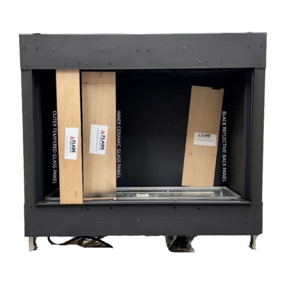
FIREPLACE GLASS INSTALLATION Below are the details on how to install your fireplaces Double Glass. The following process can also be executed in reverse to remove the Double Glass. Click here for video instructions WHERE DOES EACH GLASS PANEL GO? Once the fireplace is unpacked, locate the wooden panels, labeled with what pane of glass is installed in its place. -
Page 29: Installing Your Black Reflective Back
INSTALLING YOUR BLACK REFLECTIVE BACK Your black reflective back panel will be installed against the back wall of the fireplace using two suction cups, secured by the included reflective back brackets, and the outside lip of the burner tray along the base of the fireplace. -
Page 30: Step 2
REMOVING THE MAGNETIC FILLERS AND INNER TRIM BRACKETS Your inner ceramic glass panel can be installed after removing the left, right, and bottom fillers and trim brackets. Followed by opening the top butterfly trim to allow the installer to insert the glass into position. STEP 1: Remove the left, right, and bottom filler pieces, revealing the trim brackets used to hold your inner ceramic glass in position. - Page 31 LIFT UP AND PULL OUT YOUR LOUVERED LOWER FILLER TO REVEAL YOUR LOWER TRIM BRACKET.
-
Page 32: Step 1
STEP 2: Remove the bottom, left, and right inner trim brackets by loosening the hand screws (total of hand screws will depend on the fireplace size), releasing the trim brackets from the fireplace frame. Set aside to protect from damage. LOWER BRACKET REMOVED REMOVING LEFT AND RIGHT BRACKET... -
Page 33: Step 2
STEP 3: Locate and loosen all hand screws across the top frame of the fireplace. This will open your inner butterfly trim allowing you to insert your inner layer of ceramic glass. Note: This trim will not be removed, but will simply open to accept the inner glass... -
Page 34: Installing Your Inner Layer Of Ceramic Glass
INSTALLING YOUR INNER LAYER OF CERAMIC GLASS Using suction cups insert the inner ceramic glass behind the upper butterfly trim, push in gently, then set panel along the small holders, lining the bottom frame of the fireplace. Verify the top of your inner ceramic glass is behind your butterfly trim, pressed firmly against the non-combustible gasket around the fireplace opening. -
Page 35: Step 2
STEP 2: Once the inner ceramic glass panel is in position press in and hold the upper butterfly trim while tightening the hand screws, sealing the glass against the non-combustible gasket. UPPER BUTTERFLY TRIM BEING SECURED STEP 3: Locate and reinstall your lower trim bracket. Once in position tighten all the hand screws securing your lower trim bracket against the glass, sealing it against the non-combustible gasket. -
Page 36: Step 4
STEP 4: Locate and reinstall your lower louvered filler by placing it on its holder across the bottom frame of the fireplace. INSTALL YOUR LOWER LOUVERED FILLER STEP 5 Locate and install your left and right-side trims to secure the inner portion of your ceramic glass to the inner gasket of the fireplace frame. -
Page 37: Step 6
STEP 6 Locate and install your left and right-side fillers to give a finished appearance by covering the trims on the inner portion of your fireplace frame. -
Page 38: Installing Outer Layer Of Tempered Glass
INSTALLING OUTER LAYER OF TEMPERED GLASS Using suction cups insert the outer tempered glass in front of the upper trim tabs, push in gently, then lift panel into frame, pushing the bottom in and setting it down within its channel along the base of the fireplace frame. Verify the top of your outer tempered glass is in front of your trim tabs. -
Page 39: Installation Steps
INSTALLATION STEPS 1. Prior to starting the installation, make sure you read and understand all WARNING information in the manual. Do not start the installation if you are unclear about any of the installation related subjects. 2. Determine the following: •... -
Page 40: Large Fireplace Components And Access
- If the fireplace sits too low on the floor, the controls must be placed outside the non-combustible zone or insulated from the heat from the fireplace. ACCESS TO CONTROL BOARD AND SIT RECEIVER The Large Flare Fireplaces have built-in access to the control board, valve, and receiver modules for simpler servicing in the field. STEP 1 Using suction cups on your outer layer of glass, gently lift and pull out the tempered glass. -
Page 41: Step 1
STEP 2: Remove the left, right, and bottom filler pieces, revealing the trim brackets used to hold your inner ceramic glass in position. REMOVED MAGNETIC TRIM. LIFT UP AND OUT ON THE RIGHT AND LEFT MAGNETIC FILLERS. LIFT UP AND PULL OUT YOUR LOUVERED LOWER FILLER TO REVEAL YOUR LOWER TRIM BRACKET. -
Page 42: Step 3
STEP 3: Remove the left, right, and bottom inner trim brackets by loosening the bolts or hand screws, releasing the trim brackets from the fireplace frame. Set aside to protect from damage. LOWER BRACKET REMOVED REMOVING LEFT BRACKET REMOVING RIGHT BRACKET STEP 4: Using solid state 11mm wrench, remove the butterfly screws located above first two Double Glass fans on the right as shown in the picture below. -
Page 43: Step 2
STEP 5: Using a powered drill, release the two right-side fans by unscrewing the screws holding your fans in place, being mindful to not use too much power. STEP 6: Once the fans are released, reach into fireplace frame, pull components out and up, placing them on top of the frame for service. - Page 44 ACCESS TO THE GAS VALVE The Large Flare Fireplaces have built-in access to the control board, valve, and receiver modules for simpler servicing in the field. STEP 1: After removing your safety barrier, remove the left, right, and bottom filler pieces, revealing the trim brackets used to hold your inner ceramic glass in position.
- Page 45 STEP 2: Remove the left, right, and bottom inner trim brackets by loosening the bolts or hand screws, releasing the trim brackets from the fireplace frame. Set aside to protect from damage. LOWER BRACKET REMOVED REMOVING LEFT BRACKET REMOVING RIGHT BRACKET STEP 3 Locate the valve sitting perpendicular to the front frame, positioned just left of center on your large fireplace.
-
Page 46: Rgb Led Lights
RGB LED LIGHTS The Flare Fireplace can be ordered with optional multi-color interior RGB LED lighting. The lights allow perfect flames to be viewed across a bed of illuminated crushed glass, or any other direct vent approved media option. RGB LED – The multicolored option is controlled by a remote for the color selection. Once the color has been selected by the operator, the LED memory will remember that color for the next time the unit is turned on. -
Page 47: Rgb Led Light Power And Installation
RGB LED LIGHT POWER AND INSTALLATION Flare recommends connecting to 110V and testing your RGB LED components before installation to simplify any issues that may arise once the project has been finished around, where access to these important components may become limited. STEP 1 Remove all LED components from the shipping bag. -
Page 48: Rgb Led Electrical Diagram
RGB LED ELECTRICAL DIAGRAM LED Power Supply Can be connected to the SIT Control System Part A or Part B... -
Page 49: Led Controller And Remote
LED CONTROLLER AND REMOTE The Flare high-performance RGB LED touch remote controller adopts the most advanced PWM control technology. This remote controls all RGB LED products with 4 lines of circuits (COMMON ANODE), owning 64 thousand colors & 20 automatic changing modes to choose from. RBG Strip is using 24V DC power adapter. MATERIAL 110x52x20mm POWER... -
Page 50: Mode Selection And Remote
MODE SELECTION AND REMOTE NUMBER MODE BRIGHTNESS STATE SPEED STATE STATIC WHITE ADJUSTABLE UNADJUSTABLE WHITE COLOR GRADUAL CHANGES ADJUSTABLE ADJUSTABLE ALL COLORS GRADUAL CHANGES ADJUSTABLE ADJUSTABLE RED/GREEN/BLUE 3 COLORS GRADUAL CHANGE ADJUSTABLE ADJUSTABLE 7 COLORS JUMP TO CHANGE ADJUSTABLE ADJUSTABLE 3 COLORS JUMP TO CHANGE ADJUSTABLE ADJUSTABLE... -
Page 51: Code Matching (Gen 1 Remote): Pairing Your Gen 1 Rgb Led Remote
CODE MATCHING (GEN 1 REMOTE): PAIRING YOUR GEN 1 RGB LED REMOTE Confirm your system is correctly connected between power supply, LED controller & LED strips. Next, switch the power off and on again. Once power has been returned, press key 5 once (within 3 seconds) the moment you see the lights are on. -
Page 52: Air Shutter Adjustments
See Ex. 1 above for visual. • Example 2: The second option allows you to adjust your Flare Fireplaces air shutter by accessing it from directly underneath the fireplace. See Ex. 2 above for visual... -
Page 53: Vent Termination
CAN/CSA-B149.1 in Canada. Large Flare Fireplaces units use multiple vents, depending on the number of units used to build the system. Make sure all vents’ terminations are in the same area for flame consistency and balance inside the fireplace APPROVED PIPE This appliance is approved for use with M&G DuraVent venting and ICC. -
Page 54: Vent Pipe Specifications
VENT PIPE SPECIFICATIONS • Where a vent pipe passes through a floor or ceiling, a ceiling firestop MUST be used to retain insulation and maintain proper clearances. Use roof support brackets where needed. • Install the first section of vent pipe into the collar on top of the fireplace. •... -
Page 55: Vent Pipe Size And Quantity For Each Large Fireplace Size
VENT PIPE SIZE AND QUANTITY FOR EACH LARGE FIREPLACE SIZE SIZE VENT PIPE SIZE Flare 120 (x2) 5x8 Flare 140 (x2) 5x8 Flare 160 (x2) 5x8 Flare 180 (x3) 5x8 Flare 200 (x2) 5x8 Flare 210 (x3) 5x8 Flare 400 (x4) 5x8 NOTE: PLEASE USE THE LARGE FIREPLACE PRODUCT PAGES TO DETERMINE PIPE SIZE AND QUANTITY FOR YOUR... -
Page 56: Minimum Combustible Clearances From Vent
MINIMUM COMBUSTIBLE CLEARANCES FROM VENT Below you will find the required clearances to both the vertically and horizontally run direct vent pipe used with the Large Flare Fireplaces lineup. HORIZONTAL VENT CLEARANCES A minimum clearance of 3 inches (76mm) to the top and 1 inch (51mm) to the sides and bottom of the vent pipe on all horizontal runs to combustibles is required. -
Page 57: Minimum Height From Roof To Lowest Discharge Opening
MINIMUM HEIGHT FROM ROOF TO LOWEST DISCHARGE OPENING NOTE: The minimum of 24” horizontal clearance to any surface (such as an exterior wall) is required for any vertical terminations. For more details, please see the images below. -
Page 58: Multiple Vertical Terminations
MULTIPLE VERTICAL TERMINATIONS For multiple termination clearances please see the image below. MULTIPLE HORIZONTAL TERMINATIONS A minimum of 18” should be maintained between two horizontal terminations. NOTE: The minimum cutout dimensions or frame openings around wall venting. Make sure clearances to combustible material are maintained based on vent part used. -
Page 59: Vent Termination Clearances
VENT TERMINATION CLEARANCES ^12 inches (30cm) minimum Clearances above grade, veranda, porch, deck, or balcony **12 inches (30cm) minimum Clearance to window or door that may be opened Clearance to permanently closed window recommended to 12 inches (30cm) minimum prevent condensation on window 24 inches (76cm) minimum for Flares sized 80 and 100 inches Vertical clearance to ventilated soffit located above the 18 inches (46cm) minimum for Flares sized 30 and 70 inches... -
Page 60: Vent Restrictor Setup
• Flame lacks movement. Vent restrictor should be closed if the flame has the following characteristics: • Flame height is low. • Flame has excessive movement Document and changes to the restrictor setting and contact Flare Fireplaces is support is needed. -
Page 61: Chimney Path Installation And Planning
Fireplaces for restrictor size recommendations. • Use the empty table in the page below to document and calculate the installation vent path. • Any venting pathway that does not appear the tables below require approval from Flare Fireplaces. Note: For optimum performance and flame appearance, keep the vent length to a minimum, limit the number... -
Page 62: Large Fireplace Configuration Chart
LARGE FIREPLACE CONFIGURATION CHART The following configuration chart should be used to determine how many vent pipe stacks are required based on the unit you are installing. Note: Configuration is the same for High Glass models FRO NT FACING LEFT CO RNER FLARE-FF-120 RC-60 / LC-60 FLARE-LC-120... -
Page 63: Flare 60/60H
FLARE 60/60H Suitable for all Large Flares sized 60/60H VENT RESTRICTOR SETTING: Set 1-6 based on table below. “X” means unit will need to power vent both vent pipes to draft. -
Page 64: Flare 70/70H
FLARE 70/70H Suitable for all Large Flares sized 70/70H VENT RESTRICTOR SETTING: Set 1-6 based on table below. “X” means unit will need to power vent both vent pipes to draft. -
Page 65: Flare 80/80H
FLARE 80/80H Suitable for all Large Flares sized 80/80H VENT RESTRICTOR SETTING: Set 1-6 based on table below. “X” means unit will need to power vent both vent pipes to draft. -
Page 66: Flare 100/100H
FLARE 100/100H Suitable for all Large Flares sized 80/80H VENT RESTRICTOR SETTING: Set 1-6 based on table below. “X” means unit will need to power vent both vent pipes to draft. -
Page 67: Power Venting
POWER VENTING For unsupported vent routes (based on the gravity vent tables above) a power venting solution is required. The power venting solutions allow Flare Fireplaces to operate in vent conditions that would not be possible without the motor unit. See the Flare Power Vent Installation Manual for more specific instructions. -
Page 68: Power Venting Overview
Note: A minimum length of 12ft venting is required between the Fireplace and the power vent, Flare Fireplaces sizes 60”-70”. A minimum length of 15ft, Flare sizes 80”-100”, is required between the fireplace and the power vent. -
Page 69: Power Vent Electrical Overview
POWER VENT ELECTRICAL OVERVIEW All Flare Fireplaces power vent systems are connected to the Fireplace with a high Voltage cable, 115 Volts, 60 Hz, and 15 Amps (maximum draw). The appliance, when installed, must be electrically grounded in accordance with local codes or, in the absence of local codes, with the National Electrical Code, ANSI/NFPA 70, or the Canadian Electrical Code, CSA C22.1. -
Page 70: Gas Installation
GAS INSTALLATION WARNING! Risk of Fire or Explosion! All gas handling and installation should be performed by qualified service technician or installer. Gas build-up during line purge could ignite. Ensure adequate ventilation. Make sure there are no ignition sources/sparks or open flames. Do not change the gas valve setting! The fireplace gas valve has been preset at the factory. -
Page 71: Gas Valve Overview
GAS VALVE OVERVIEW Have the gas supply line installed in accordance with local codes, if any. If not available, follow ANSI 223.1. Installation should be done by a qualified installer approved and/or licensed as required by the locality (in the Commonwealth of Massachusetts installation must be performed by a licensed plumber or gas fitter). -
Page 72: Using A Reducer To De-Rate Your Fireplace
USING A REDUCER TO DE-RATE YOUR FIREPLACE Flare Fireplaces appliances use the SIT ProFlame II valve and are tested/approved for installations at elevations of 0–4500 feet (0 – 1372 meters) above sea level using the standard burner orifice sizes. At the time of installation, it must be determined by the installer if the appliance needs to be de-rated for elevations above 4500 feet. -
Page 73: Adding The Flare De-Rating Reducer
ADDING THE FLARE DE-RATING REDUCER Add the de-rating reducer when your fireplace is being installed at elevations over 4500 ft above sea level. Please contact your local gas supplier for de-ration requirements in your area. STEP 1 Shut off gas, remove power, and locate your gas valve. Once disconnected, verify direction of gas flow by locating the flow-arrow on top of the valve. -
Page 74: Orifice Size
The installation of this appliance REQUIRES the implementation of a readily accessible Manual Gas Shut Off. Confirm requirements of location and shut off type with your local codes. NOTE: The Electronic Ignition of Flare Fireplaces DOES NOT satisfy the requirement for a Manual Gas Shut Off. See below for example of Manual Gas Shut Off... -
Page 75: Liquid Propane Usage In A Flare Fireplace
FIREPLACE TECHNICIAN. USE ONLY FLARE FIREPLACE LP CONVERSION KIT. ALWAYS MEASURE GAS INLET PRESSURE AND OUTLET PRESSURE POST CONVERSION Your Fireplace may be shipped to support Liquid Propane Gas. Check your Flare Fireplaces gas rating plate at the back of your valve to confirm the gas type. -
Page 76: Commonwealth Of Massachusetts
COMMONWEALTH OF MASSACHUSETTS STATE OF MASSACHUSETTS CARBON MONOXIDE Detector/Vent Terminal Signage Requirements for all side wall horizontally vented gas fueled equipment installed in every dwelling, building or structure used in whole or in part for residential purposes, including those owned or operated by the Commonwealth and where the side wall exhaust vent termination is less than seven (7) feet above finished grade around the venting, including but not limited to decks and porches, the following requirements shall be satisfied: 1. -
Page 77: Double Glass Overview
DOUBLE GLASS OVERVIEW With an effort to make our fireplaces safer, Flare Fireplaces is offering our full line of products with double glass safety barrier technology. The Flare Fireplace double glass is built with two layers of glass. The design allows cool air to flow between the two layers, with the help of built-in blowers, significantly lowering the temperature of the external glass, making it safe for a brief touch. -
Page 78: Double Glass Requirements
DOUBLE GLASS REQUIREMENTS The double glass design depends on the blower’s ability to move room temperature air from the lower air intake, up between the internal and external glass, through the chase above the fireplace, and out the upper heat release. These relatively quiet blowers cannot be turned off and are required for the continued operation of your Double Glass system. -
Page 79: Air Intake Sizing
AIR INTAKE SIZING The following sizing chart represents the minimums for your heat release. Flare recommends making these openings as large as possible to keep the system even cooler than required. The elements must be followed for successful and safe fireplace operation. Not following these requirements will void your warranty. Size Vent Size Units Size... -
Page 80: Power Requirements
POWER REQUIREMENTS Double Glass: 110V, 15A Outlet (Dedicated circuit is optional but recommended) or directly wired. When using an outlet, make sure the outlet is accessible in the event of servicing. **No additional power source needed for optional RGB-LEDs. TELEVISION MOUNTING ABOVE THE FIREPLACE The Flare Fireplace frameless design directs the heat from the fireplace into the fireplace chase to be released from the top vent opening. -
Page 81: Television Install - Flat Example
TELEVISION INSTALL – FLAT EXAMPLE *THE EXAMPLE SHOWN ABOVE IS NOT A TO SCALE RENDERING OF EVERY FIREPLACE STYLE AND VENT PLACEMENT OFFERED BY FLARE BUT MEANT TO CONVEY RELEVANT MEASUREMENTS FOR USE ON ALL UNIT INSTALLATIONS. FOR EXACT DRAWINGS OF THE FIREPLACES AND THEIR VENT PLACEMENT PLEASE DOWNLOAD DIMENSION OR FRAMING GUIDES FROM OUR DIRECT VENT DOWNLOAD CENTER WARNING... -
Page 82: Television Install - Recessed Example
TELEVISION INSTALL – RECESSED EXAMPLE Directly over the fireplace the television recess should be no deeper than 6” inches. A minimum of 12” above the top of the fireplace glass opening to the underside of the recess. Extending the overhang to the max of 8” and recessing into the cavity to the max of 6” can create an overhang up to 14”... -
Page 83: Television Install Recess - 45 Degree Elbow On Top To Clear Vent Pipe
TELEVISION INSTALL RECESS – 45 DEGREE ELBOW ON TOP TO CLEAR VENT PIPE When planning a TV recess, clearance to the vent pipe in the chase is critical and needs to be a minimum of 1” to the non-combustible recessed wall. This is to prevent heat from radiating from the vent to the recessed wall and being transferred to the TV. -
Page 84: Television Install - Flush, With Mantel
TELEVISION INSTALL – FLUSH, WITH MANTEL The TV must be at least 12 inches total above the glass of the fireplace. A mantel at least 1 inch thick and 6 inches deep should be installed a minimum of 8 inches above the glass. The TV must be at least 2 inches above the mantel and 1 inch back from the edge of the mantel. -
Page 85: Framing Clearances
FRAMING CLEARANCES Below are the specifications for metal and wood framing around Flare Fireplaces. METAL FRAMING FOR MORE DETAILED FRAMING INFORMATION PLEASE REFER TO YOUR UNIT SPECIFIC FRAMING GUIDE... -
Page 86: Wood Framing
WOOD FRAMING FOR MORE DETAILED FRAMING INFORMATION PLEASE REFER TO YOUR UNIT SPECIFIC FRAMING GUIDE... -
Page 87: Important Clearances
WARNING! - Flare fireplaces are not designed to be load baring or support weight of any architectural framing. All framings should be self-supported, supported by back wall, side wall, or ceiling. Attempting to mount framing to a fireplace subjects’... - Page 88 5. Combustible Mantel Clearance - Clearance will vary according to the mantel depth and height. 6. Fireplace shelf enclosure - The minimum height to the inside of a shelf above the top of the fireplace is 6 inches (12 inches above the glass). The shelf must be built with non-combustible material at least 5/8” thick. Due to the low size of shelf enclosure, it is recommended to build the enclosure using a Skamol board.
- Page 89 11. Minimum clearance directly above the fireplace inside the chase - non-combustible – All non-combustible studs to be installed a minimum of ½” away from the fireplace. Metal studs should not connect to the fireplace or touch the fireplace. Doing so will result in heat transfer from the fireplace to the metal stud. Make sure not to block hot air flow to the heat release.
- Page 90 14. Hearth Clearances - A. Clearance to an uncovered combustible hearth below the glass is 2 inches as seen in EXAMPLE 1 B. When bringing your hearth to glass height it must be non-combustible for the first 7” extending from the glass before any combustible material can be used to finish the hearth.
-
Page 91: Example 1
16. Finishing Around Front of Fireplace Non-combustible finishing material (i.e., cement board, brick, stone, tile & minimum ½” inch Type X fire rated drywall) MUST be used to finish around the front of the appliance. Covered combustible material, can also be used to finish around the front of the fireplace, but only if the proper distance from the fireplace is maintained. -
Page 92: Example 2
EXAMPLE 2 NOTE: DO NOT CONNECT MATERIALS TO OR DRILL INTO THE METAL FIREPLACE FRAME. THIS CAN RESULT IN EXCESSIVE HEAT TRANSFER AND/OR DAMAGE TO THE FIREPLACE AND SURROUNDING MATERIALS. -
Page 93: Example 3
EXAMPLE 3 NOTE: DO NOT CONNECT MATERIALS TO OR DRILL INTO THE METAL FIREPLACE FRAME. THIS CAN RESULT IN EXCESSIVE HEAT TRANSFER AND/OR DAMAGE TO THE FIREPLACE AND SURROUNDING MATERIALS. -
Page 94: Non-Combsutible / Combustible Materials Specifications
NON-COMBSUTIBLE / COMBUSTIBLE MATERIALS SPECIFICATIONS Non-Combustible Materials Specification Material which will not ignite and burn. Such materials are those consisting entirely of steel, iron, brick, tile, concrete, slate, glass or plasters, or any combination thereof. Materials that are reported as passing ASTM E 136, Standard Test Method for Behavior of Materials in a Vertical Tube Furnace at 750 ºC shall be considered non-combustible materials. -
Page 95: Combustible Mantel Clearance
COMBUSTIBLE MANTEL CLEARANCE Combustible mantel clearance can vary per the mantel size and location. Use the chart and provided table for information on mantel install. Do not anchor any mantel or shelf to the fireplace. Only use metal studs above the fireplace as anchor points. -
Page 96: Clearance To Sprinkler System
CLEARANCE TO SPRINKLER SYSTEM In a situation where a sprinkler head is installed within proximity to a Heat Release, the diagram below MUST be followed. The distance between the sprinkler head and Heat Release opening cannot be less than 60” in length at every point from the origin of the Heat Release. -
Page 97: Heat Release Sizing
HEAT RELEASE SIZING The following sizing chart represents the minimums for your heat release. Flare recommends making these openings as large as possible to keep the system even cooler than required. The elements must be followed for successful and safe fireplace operation. Not following these requirements will void your warranty. Size Vent Size Units Size... -
Page 98: Examples Of Heat Releases
EXAMPLES OF HEAT RELEASES DROP WALL SIDE VENTS SLOT DIFFUSER... -
Page 99: Shadow Line
KEEPING THE WALL ABOVE YOUR FIREPLACE AS COOL AS POSSIBLE The Flare Fireplaces installation guide calls for the minimum heat release sizing on your fireplace build, guaranteeing your fireplace operates within the safely set nationwide guidelines for direct vent fireplaces. To achieve cooler temperatures, enlarge the heat release to increase the amount of hot air being pulled out of the fireplace cavity. -
Page 100: Air Intake Sizing
AIR INTAKE SIZING The following sizing chart represents the minimums for your heat release. Flare recommends making these openings as large as possible to keep the system even cooler than required. The elements must be followed for successful and safe fireplace operation. Not following these requirements will void your warranty. Size Vent Size Units Size... -
Page 101: Examples Of Air Intakes
EXAMPLES OF AIR INTAKES FLOATING HEARTH TOE-KICK REVEAL LEFT/RIGHT/BOTTOM SLOTS... -
Page 102: Slot Diffuser - Bottom
SLOT DIFFUSER – BOTTOM KEEPING YOUR DOUBLE GLASS AS COOL AS POSSIBLE The Flare Fireplaces installation guide calls for the minimum requirements for the air intake sizing on your double glass fireplace build, guaranteeing your fireplace operates within the safely set nationwide guidelines for direct vent fireplaces. -
Page 103: Flare Front, See-Through, And Corner Style Fireplace Clearances
FLARE FRONT, SEE-THROUGH, AND CORNER STYLE FIREPLACE CLEARANCES FLATE - SIDE VIEW Warning! – Maintain open Air flow between the fireplace and drywall. Make sure there are no cables in the cavity, or any materials blocking hot air flow to the required heat release. - Page 104 Top Vent system - Hot Airflow outlet from the wall enclosure MUST remain open. The outlet must be at the top part of the enclosure, but not necessarily at the front, if the measurements below are maintained. For fireplaces sized 80” & 100”– vent area must be at least 200 open square inches. For fireplaces sized 60”...
-
Page 105: L-Shape - Side View
L-SHAPE – SIDE VIEW Warning! – Maintain open Air flow between the fireplace and drywall. Make sure there are no cables in the cavity, or any materials blocking hot air flow to the required heat release. - Page 106 Top Vent system - Hot Airflow outlet from the wall enclosure MUST remain open. For Flare See Through fireplace, open vent must exist in both sides of the glass. The outlet must be at the top part of the enclosure but not necessarily at the front if the measurements below are maintained.
-
Page 107: Home Automation
This wire can be extended up to 80 FT for integration into a new or existing Home Automation System. Please contact Flare Support for additional information on appropriate relays to be used. 1. Flare Fireplaces ship with this wall switch 2. This is the cable that comes connected to this wall switch. -
Page 108: Electrical Diagram
ELECTRICAL DIAGRAM Below are the electrical diagrams and details related to how the double glass fireplaces are connected or need to be connected when servicing. ELECTRICAL – DOUBLE GLASS AND POWER VENTED UNITS Aux Port (X13) is used as a switch to open and close the relay port on the control system. (This actively monitors your fans and power vent controlling ignition if there is a failure) The wall switch is connected to the X4 and X8 port on your SIT receiver module. -
Page 109: Double Glass Control Board And Internal Led Light Guide
DOUBLE GLASS CONTROL BOARD AND INTERNAL LED LIGHT GUIDE... -
Page 110: Double Glass Board Led Lights Explained
DOUBLE GLASS BOARD LED LIGHTS EXPLAINED (*NUMBER OF FANS WILL CHANGE BASED ON MODEL SIZE*) The first two dipswitch sets (DSW1 & DSW2), in the “DOUBLE GLASS FANS BYPASS” area of the Double Glass Board, are used to determine which fans will be monitored by the board, verifying all fans are working properly before allowing the fireplace burner to start. -
Page 111: Electrical - Power Vent Board
ELECTRICAL – POWER VENT BOARD... -
Page 112: Replacement Parts
REPLACEMENT PARTS Please contact your local Flare Fireplaces Dealer to purchase any replacement parts(s). Please provide a description and part number. Please make sure you use a certified fireplace installer for any service related to your fireplace. -
Page 113: Maintenance
MAINTENANCE WARNING! • It is recommended that a qualified service technician perform a routine inspection at the beginning of each heating season. • Disconnect power before attempting maintenance or repair of the fireplace. • Installation and maintenance must be performed by an authorized qualified installer, service agency or gas supplier. -
Page 114: Yearly Service
YEARLY SERVICE COMMERCIAL FIREPLACES MAY NEED MORE REGULAR SERVICE Failure to inspect and maintain the fireplace may lead to improper combustion and a potentially dangerous situation. We recommend the following procedures be done by a qualified technician. Glass Maintenance • Always use suction cups to remove the fireplace glass. Use the manual procedure for instruction on how to remove the fireplace glass. -
Page 115: Maintenance Log
MAINTENANCE LOG Flare Fireplaces – Maintenance log The service technician should use the following document. A copy should be kept with the technician and owner for future reference Service Date: ___________________ Unit Information Model Type and Size: ____________________________________________________ Serial #: _______________________________________________________________... -
Page 116: Warranty Policy
WARRANTY POLICY Flare Fireplaces subjects every fireplace and component to rigorous testing to verify it is free from any defects before it leaves our warehouse. Flare Fireplaces photographs and documents the fireplace and all components’ moments before shipping them to our nationwide network of authorized dealers for installation, verifying full operation of the fireplace and all components. - Page 117 Flare Fireplaces is not responsible for installation, operational or environmental conditions beyond our control. • Flare Fireplaces shall in no event be liable for any special, indirect, or consequential damages of any nature which are more than the original purchase price of the product. •...
- Page 118 WARRANTY VOIDED WHEN • An unauthorized media type is used in the firebox. • The appliance has been over-fired or operated in atmospheres contaminated by chlorine, fluorine, or other damaging chemicals. Over-firing can be identified by, but not limited to, warped plates or pipes, rust colored iron or bubbling, cracking and discoloration of steel or enamel finishes.
Need help?
Do you have a question about the Large Flare Front 120 and is the answer not in the manual?
Questions and answers