Table of Contents
Advertisement
Quick Links
AIR CONDITIONERS CITY MULTI
TECHNICAL & SERVICE MANUAL
Series PDFY
<Indoor unit>
PDFY-P06NMU-E,PDFY-P08NMU-E
Models
PDFY-P12NMU-E,PDFY-P15NMU-E
PDFY-P18NMU-E,PDFY-P24NMU-E
PDFY-P27NMU-E,PDFY-P30NMU-E
PDFY-P36NMU-E,PDFY-P48NMU-E
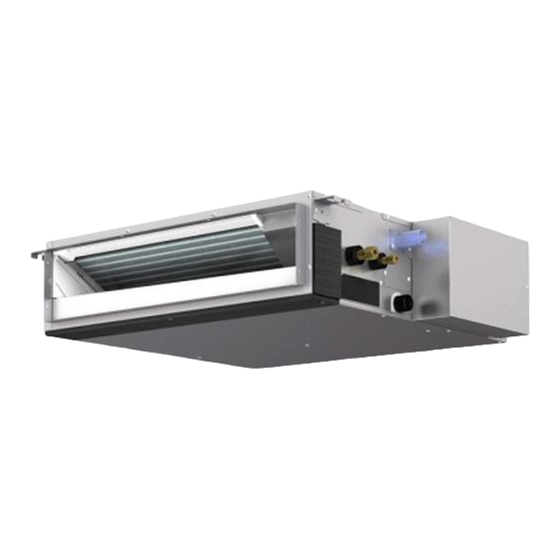
Ceiling Concealed Built-in
CONTENTS
SAFETY PRECAUTIONS ·························
1. FEATURES············································
2. PART NAMES AND FUNCTIONS ········
3. SPECIFICATION ···································
4. OUTLINES AND DIMENSIONS············
5. WIRING DIAGRAM ·····························
7. TROUBLE SHOOTING························
8. DISASSEMBLY PROCEDURE ···········
For use with the R410A & R22
2005
1
3
4
6
8
10
12
13
18
Advertisement
Table of Contents

Related Manuals for Mitsubishi Electric CITY MULTI PDFY Series


Summary of Contents for Mitsubishi Electric CITY MULTI PDFY Series
-
Page 1: Table Of Contents
2005 AIR CONDITIONERS CITY MULTI TECHNICAL & SERVICE MANUAL Ceiling Concealed Built-in Series PDFY <Indoor unit> PDFY-P06NMU-E,PDFY-P08NMU-E Models PDFY-P12NMU-E,PDFY-P15NMU-E PDFY-P18NMU-E,PDFY-P24NMU-E PDFY-P27NMU-E,PDFY-P30NMU-E PDFY-P36NMU-E,PDFY-P48NMU-E CONTENTS SAFETY PRECAUTIONS ························· 1. FEATURES············································ 2. PART NAMES AND FUNCTIONS ········ 3. SPECIFICATION ··································· 4. OUTLINES AND DIMENSIONS············ 5. -
Page 2: Safety Precautions
Install the air unit at a place that can withstand its weight. is shorted and operated forcibly, or parts other than those specified - Inadequate strength may cause the unit to fall down, resulting in by Mitsubishi Electric are used, fire or explosion may result. injuries. •... - Page 3 Precautions for devices that use Warning: • Note the following when building a heater in the air R410A refrigerant conditioning system. - Leave enough space between units for proper ventilation so that Caution: the indoor unit temperature does not exceed 40˚C when •...
-
Page 4: Features
FEATURES Ceiling Concealed Built-in Series PDFY Indoor unit Cooling capacity/Heating capacity Models Btu / h PDFY-P06NMU-E 1.8 / 2.0 6000 / 6700 PDFY-P08NMU-E 2.3 / 2.6 8000 / 9000 PDFY-P12NMU-E 3.5 / 4.0 12000 / 13500 4.4 / 5.0 PDFY-P15NMU-E 15000 / 17000 PDFY-P18NMU-E 5.3 / 5.9... -
Page 5: Part Names And Functions
PART NAMES AND FUNCTIONS Indoor (Main) Unit Air outlet Air inlet Remote controller [PAR-21MAA] Once the controls are set, the same operation mode can be repeated by simply pressing the ON/OFF button. G Operation buttons TEMP. ON/OFF MENU ON/OFF FILTER BACK MONITOR/SET CHECK... - Page 6 [Display] CENTRALLY CONTROLLED 1Hr. ON OFF CLOCK CHECK FILTER CHECK MODE TEST RUN STAND BY ERROR CODE FUNCTION NOT AVAILABLE DEFROST TEMP. ON/OFF A Current time/Timer B Centralized control C Timer OFF D Timer indicator E Operation mode: COOL, DRY, AUTO, FAN, HEAT...
-
Page 7: Specification
SPECIFICATION 3-1. Specification PDFY-P-NMU-E Item Model PDFY-P06NMU-E PDFY-P08NMU-E PDFY-P12NMU-E PDFY-P15NMU-E PDFY-P18NMU-E Power sourse 208/230V, 60Hz Cooling Capacity BTU/h 6000 8000 12000 15000 18000 Heating BTU/h 6700 9000 13500 17000 20000 Height 11-5/8 Dimension Width 27-31/32 37-13/16 Depth 28-15/16 Net weight Airflow rate /min 6.0-6.5-7.5-8.5... - Page 8 3-2. Electrical parts specifications Model PDFY- PDFY- PDFY- PDFY- PDFY- PDFY- Symbol P06,08,12 P15,18 P24,27 Parts NMU-E NMU-E NMU-E NMU-E NMU-E NMU-E name Tranrsformer (Primary) 240V 60Hz (Secondary) (23.5V 0.9A) Room Resistance 0˚C[32˚F]/15kΩ,10˚C[50˚F]/9.6kΩ,20˚C[68˚F]/6.3kΩ,25˚C[77˚F]/5.4kΩ, temperature TH21 30˚C[86˚F]/4.3kΩ,40˚C[104˚F]/3.0kΩ thermistor Liquid pipe Resistance 0˚C[32˚F]/15kΩ,10˚C[50˚F]/9.6kΩ,20˚C[68˚F]/6.3kΩ,25˚C[77˚F]/5.4kΩ, TH22 thermistor 30˚C[86˚F]/4.3kΩ,40˚C[104˚F]/3.0kΩ...
-
Page 9: Outlines And Dimensions
OUTLINES AND DIMENSIONS PDFY-P06·08·12·15·18·24·27·30NMU-E... - Page 10 PDFY-P36·48NMU-E...
-
Page 11: Wiring Diagram
WIRING DIAGRAM PDFY-P06·08·12·15·18·24·27·30NMU-E... - Page 12 PDFY-P36·48NMU-E...
-
Page 13: Refrigerant System Diagram
REFRIGERANT SYSTEM DIAGRAM Gas pipe thermistor TH23 Gas pipe Liquid pipe thermistor TH22 Flare connection Heat exchanger Linear expansion valve Strainer (#100mesh) Strainer (#100mesh) Room temparature thermistor TH21 mm <in.> Capacity PDFY-P06,08,12,15NMU-E PDFY-P18NMU-E Item ø R410A 12.7(1/2) Gas pipe ø ø... -
Page 14: Trouble Shooting
TROUBLE SHOOTING 7-1. How to check the parts Parts name Check points Room temparature Disconnect the connector, then measure the resistance using a tester. thermistor (Sorrounding temperature 10˚C~30˚C[50˚F~86˚F]) (TH21) Liquid pipe thermistor (TH22) Normal Abnormal Gas pipe thermistor (Refer to the thermistor) (TH23) 4.3kΩ... - Page 15 <Thermistor Characteristic graph> < Thermistor for lower temperature > Room temparature thermistor(TH21) Thermistor for Liquid pipe thermistor(TH22) lower temperature Gas pipe temparature thermistor(TH23) Drain sensor(DS) =15kΩ ± 3% Thermistor R Fixed number of B=3480kΩ ± 2% Rt=15exp { 3480( 273+t 0˚C 32˚F 15kΩ...
- Page 16 <Output pulse signal and the valve operation> Output Output : 1 ¡ 2 ¡ 3 ¡ 4 ¡ 1 (Phase) Closing a valve Opening a valve : 4 ¡ 3 ¡ 2 ¡ 1 ¡ 4 ø1 The output pulse shifts in above order. ø2 ✻...
- Page 17 Operation by switch Switch Pole Remarks Function Thermistor<Intake temperature Indoor unit Built-in remote controller Address board detection>position Filter crogging detection Provided Not provided <At delivery> Filter life 2,500hr 100hr 1 2 3 4 5 6 7 8 9 10 Air intake Effective Not effective Remote indication switching...
- Page 18 Switch Pole Operation by switch Remarks Address board MODEL P06~12 P15~24 VOLT <At delivery> 0.321 0.401 0.200 0.240 0.120 0.160 in.WG in.WG in.WG in.WG in.WG in.WG (80Pa) (100Pa) (50Pa) (60Pa) (30Pa) (40Pa) Option 0.200 0.240 0.321 0.401 0.200 0.321 0.240 0.401 0.200 0.401...
-
Page 19: Disassembly Procedure
DISASSEMBLY PROCEDURE 8-1 CONTROL BOX Be careful removing heavy parts. OPERATING PROCEDURE PHOTOS 1.Removing the control box cover (1)Remove the fixing screws(two) of the cover(A) and remove the cover. Fig.1 8-2 THERMISTOR (Liquid piping temperature detection) OPERATING PROCEDURE PHOTOS 1.Removing the cover (1)Remove the fixing screws(two) of the cover(C) and remove the cover. - Page 20 8-3 THERMISTOR (Intake air temperature detection) Be careful removing heavy parts. OPERATING PROCEDURE PHOTOS 1.Removing the thermistor and thermistor holder (1)Pull out the thermistor holder(F) and thermistor (G) which are fixed the control box. Fig.1 (F),(G) 8-4 DRAINPAN OPERATING PROCEDURE PHOTOS 1.Removing the cover (1)Remove the fixing screws of the cover(H) and...
- Page 21 8-5 THERMISTOR (Gus piping temperature detection) OPERATING PROCEDURE PHOTOS 1.Removing the cover (1)Remove the fixing screw of the cover(J) and remove the cover. 2.Removing the thermistor (1)Remove the thermistor(K), from the thermistor holder(L), which are installed on the copper tube. Fig.1 Fig.2 (K),(L)
- Page 22 8-6 FAN and FAN MOTOR OPERATING PROCEDURE PHOTOS 1.Removing the filter (1)Press the tabs of the filter and remove the filter in the direction of the arrow 1. 2.Removing the bottom plate (1)Remove the fixing screws (two) of the bottom plate(N) and remove the plate.
- Page 23 8-7 HEAT EXCHANGER OPERATING PROCEDURE PHOTOS 1.Removing the drainpan with procedure 8-4 2.Removing the cover(J) with procedure 8-5 3.Removing the Heat exchanger (1)Remove the fixing screws of the heat exchang- er(S) and remove the heat exchanger. Fig.1 Fig.2...
- Page 24 HEAD OFFICE: MITSUBISHI DENKI BLDG., 2-2-3, MARUNOUCHI, CHIYODA-KU, TOKYO 100-8310, JAPAN Issued in Aug. 2005 HWE05160 New publication, effective Aug. 2005 Printed in Japan Specifications subject to change without notice...
Need help?
Do you have a question about the CITY MULTI PDFY Series and is the answer not in the manual?
Questions and answers