
Related Manuals for PowerWalker MBP 1-1


Summary of Contents for PowerWalker MBP 1-1
- Page 1 PDU for VFI ICR IoT 6-10kVA Installation and user manual Service and support: Call your local service representative...
- Page 2 . his manual contains important instructions that should be followed during installation and maintenance of the MBP. The MBP models that are covered in this manual are intended for installation in an environment within 0 to 50°C, free of conductive contaminant. pecial s'mbols serve the warnin associated with the ris! of electric shoc! s"m ol.
- Page 3 afet' of persons Terminal blocks may be energized even if the system is disconnected from the AC power source. Dangerous voltage levels are present within the system. It should be opened exclusively by qualified service personnel. The system must be properly grounded, always connect the earth wire first. ...
-
Page 4: Table Of Contents
CONTENTS 1 Introduction ....................1 1.1 Environmental protection ................1 2 Product Overview ................... 2 2.1 Model list ....................... 2 2.2 Presentation ....................2 3 Installation ....................4 3.1 Unpacking and Inspecting................4 3.2 Checking the accessory kit ................4 3.3 Mechanical Installation .................. -
Page 5: Introduction
1 Introduction Thank you for selecting MBP(Maintenance Bypass modular) to protect your electrical equipment. The MBP allows service person to service or replace the UPS without interrupting the connected loads. Besides, it also allow you apply for below extension used Terminal block connection design enable the MBP connect to other type UPS. -
Page 6: Product Overview
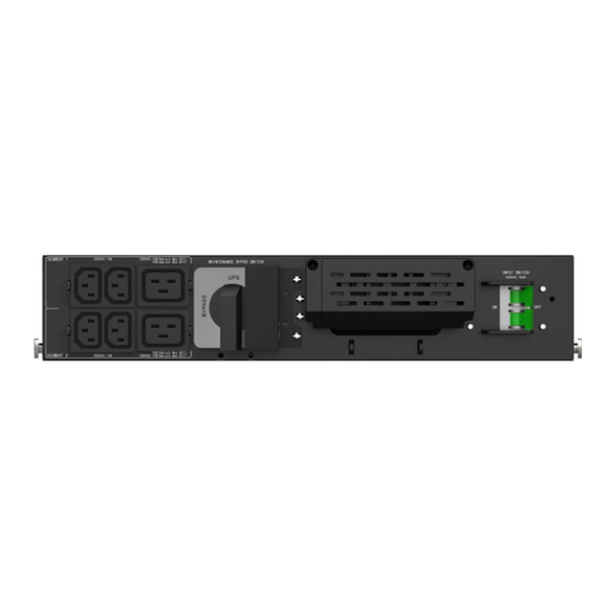
2 Product Overview ode i t 1. The weight in this table is reference only, please see the labels on the carton for details. <. Dimension ‘D’ is chassis only. roduct 0et Weights (kg) Dimensions (mm) W / ? / D PDU for VFI ICR IoT 6-10kVA 1-1 <.B... - Page 7 +ear anel P1--*3 utput socket group (programmable) <. aintenance bypass switch 3. #nput 7 utput terminal ( onnected to power and load) B. #nput switch . +GB port(including E Detect and +T model 2. #nput 7 utput terminal ( onnected to & >) 8ront anel +ear anel...
-
Page 8: Installation
- I t The system may be installed only by qualified electricians in accordance with applicable safety regulations. " c0i & d I "ecti & &npacking the unit in a low-temperature environment may cause condensation occurred in and on the cabinet. Do not install the unit until the inside and outside of the unit are absolutely dry (ha,ard of electric shock). -
Page 9: Mechanical Installation
is odel support < installation odes1 +ac! installation and o er installation #t is reco ended to connect Cca les for & S #nput 7 OutputD and C detection ca leD to t e efore installing 6 +e o e t e co er of ter inal loc!s and connect Cca les for & S #nput7 OutputD to ter inal loc!s refer to t e indication on rear panel 1*-*34 1--*34... - Page 10 - - * -ssu e t at "ou alread" purc ased our & S and fi/ t e & S in to er position 6 Our & S pro ided < positions to install t e , needed additional space is as #t is reco ended to select C9eft positionD as "our final installation according to t e configured lengt of Cca les for &...
- Page 11 osition 6(+ear of rac!* • osition <(8ront of rac!* • 6 #nstall C+ail !itD to rac! ca inet " scre s and as ers...
-
Page 12: Power Cables Connection
< Slide into Crail !itD and a!e sure loc! " t e < clips is c apter introduces o to connect to & S, and connect - #N7O& ca le to - . * 5 & $ & efore po er ca les connected, #nsert C detection ca leD to t e port C .% % D on t e rear of &... - Page 13 onnect Cca les for & S #nput7 OutputD to & S ter inal loc!s refer to indication *-* m d 4 --* m d 4 - . + 5 & $ AC C # 1AC lease refer to & S user anual for upstrea protection and do nstrea s itc +eco ended ca le ini u cross-sectional area odel...
- Page 14 ?ig lea!age current1 %art connection essential efore connecting suppl" is t"pe of connection ust e carried out " qualified electrical personnel efore carr"ing out an" connection, c ec! t at t e upstrea protection de ices (Nor al - source* are open LOL (Off* 6 +e o e t e co er of ter inal loc! <...
- Page 15 1--*34 is odel support < ode setting as elo , default is setting it 3-6 ode 6-6 ode S ort C input ter inal 9679<793D it C us arD, t en connect - ca le 3-6 ode 8or ca les ell fi/ed, it is reco ended to tie t ese ca les to t e con e/ of rear-panel...
-
Page 16: Service Operation
" lease a!e sure t e & S is turned to "pass ode efore rotating t e aintenance s itc to "pass position 6 +e o e t e C aintenance s itc co erD, t e & S ill turn to "pass auto aticall"... -
Page 17: How To Disconnect Cables Between Mbp And Ups
! ! # is is to disconnect Cca les for & S #nput 7 OutputD and C detection ca leD e pictures as elo are e/a ples of C+ac! positionD onl" 6 &nloc! t e clips and pull out its position s oot l", t en rotate t e as elo <... -
Page 18: How To Detect The Ebm To This System
is is to connect t e Cconfigured % D to a s"ste (& S+ * it C% detection ca leD as elo... -
Page 19: Specifications
" ! $ ! 6 %lectrical input—refer to t e & S input specification < %lectrical output—refer to t e & S output specification Nor al output 60- & 62- Output soc!et group rogra a le output 60- & 62- Outlet soc!et group ( rogra a le* can e set on t e 9 .
Need help?
Do you have a question about the MBP 1-1 and is the answer not in the manual?
Questions and answers