Table of Contents
Advertisement
Quick Links
Advertisement
Table of Contents
Troubleshooting

Related Manuals for Emerson SOLAHD S4KC Series


Summary of Contents for Emerson SOLAHD S4KC Series
- Page 1 Industrial On-Line UPS - 120 V, 700 VA - 3000 VA S4KC Series Instruction Manual...
- Page 2 Appleton Group assumes no responsibility, and disclaims all liability for damages resulting from use of this information or for any errors or omissions. The SolaHD and Emerson logos are registered in the U.S. Patent and Trademark Office. All other product or service names are the property of their registered owners.
-
Page 3: Table Of Contents
S4K2UC SEriES USEr mAnUAL | iii Contents Important Safety Precautions Save these instructions ..........6 Battery Safety notes . - Page 4 iv | Contents 2.0 Installation 2.1 Unpacking & inspection ......... . 15 2.2 What’s included .
- Page 5 S4K2UC SEriES USEr mAnUAL | v 5.0 Communication 5.1 intelliSlot Communication Cards ........31 5.1.1 multiLink .
-
Page 6: Important Safety Precautions
6 | important Safety instructions imPOrTAnT SAFETy PrECAUTiOnS warning Observe all cautions and warnings in this manual. Failure to do so may result in serious injury or death. Refer all UPS and battery service to properly trained and qualified service personnel. Do not attempt to service this product yourself and never work alone. -
Page 7: Battery Safety Notes
S4K2UC SEriES USEr mAnUAL | 7 This UPS is not for use in a computer room as defined in the standard for the Protection of Electronic Computer/Data Processing Equipment, AnSi/nFPA 75. The S4K2U3000-C was investigated under 30 A branch circuit in accordance with the national Electrical Code, AnSi/nFPA 70, to reduce the risk of fire;... -
Page 8: Glossary Of Symbols
8 | important Safety instructions glossary of Symbols Risk of electrical shock Indicates caution followed by important instructions AC input AC output Requests the user to consult the manual Indicates the unit contains a valve-regulated lead acid battery PbH2SO4 Recycle DC voltage Equipment grounding conductor Bonded to ground... -
Page 9: Product Description
S4K2UC SEriES USEr mAnUAL | 9 1.0 Product Description The SolaHD S4K2UC Series is a compact, on-line uninterruptible power system (UPS) that continuously conditions and regulates its output voltage. it is designed to supply microcomputers and other sensitive equipment with clean sine wave input power. -
Page 10: Appearance & Components
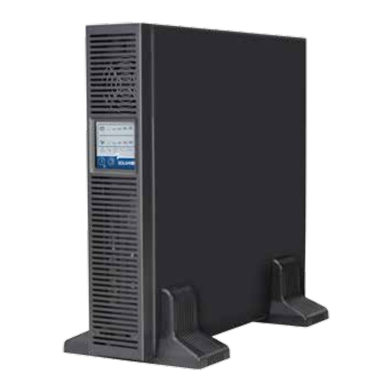
10 | 1.0 Product Description 1.3 appearance & Components 1.3.1 Front Panel & Controls The SolaHD S4K2UC rack/tower models, in various power ratings, have the same general appearance, controls and features (see Figure 1). The various rack/tower models differ largely in the receptacle type. Ventilation Slots Operation and Display Panel Figure 1: S4K2UC rack/tower models—front view... - Page 11 S4K2UC SEriES USEr mAnUAL | 11 700 VA, 1000 VA, 1500 VA Models Input Power Plug and Cable 5-15P Input Circuit USB Port Breaker IntelliSlot Port Output Receptacles, 5-15R External Terminal Block Battery Communication Connector Cooling 2000 VA Model Input Power Plug and Cable, 5-20P Input Circuit USB Port...
-
Page 12: Major Components
12 | 1.0 Product Description 1.4 Major Components The operating principle of the UPS is illustrated in Figure 3. Input Output Dynamic Bypass SPD & EMI/ Rectifier / Inverter RFI Filters DC-DC Converter Battery Battery Charger L2/N L2/N Figure 3: Operating principle diagram The UPS is composed of utility input, SPD and Emi/rFi filters, rectifier/PFC, inverter, battery charger, DC-DC converter, battery, dynamic bypass, and UPS output. -
Page 13: Inverter
S4K2UC SEriES USEr mAnUAL | 13 1.4.3 Inverter in normal operation, the S4K2UC’s inverter utilizes the DC output of the PFC rectifier to produce precise, regulated sine wave AC power. When utility power fails, the inverter receives DC power from the DC-DC converter. in either operation mode, the UPS inverter is online, continuously generating clean, precise, regulated AC output power. -
Page 14: Battery Mode
14 | 1.0 Product Description 1.5.3 Battery Mode The S4K2UC enters Battery mode when utility power fails or is outside acceptable values. The battery system supplies power through the DC-DC converter to the inverter to generate clean AC power for the connected loads. When the S4K2UC enters Battery mode, the UPS sounds a half-second beep at 10-second intervals. -
Page 15: Installation
S4K2UC SEriES USEr mAnUAL | 15 2.0 installation 2.1 Unpacking & inspection Unpack the UPS and conduct the following checks: inspect the UPS for shipping damage. if any shipping damage is found, report it to the carrier and your local dealer •... -
Page 16: Tower Installation
16 | 2.0 installation 2.4 Mechanical installation The S4K2UC may be installed as a tower or in a rack, depending on space and use considerations. The S4K2UC may be used alone, as a single UPS, or with up to four battery cabinets. NOTE: When installing the UPS or making input/output connections, comply with all relevant safety codes and standards. - Page 17 S4K2UC SEriES USEr mAnUAL | 17 b. Using the finger grips on the display panel, gently pull and rotate 90 degrees clockwise and snap it back into posi- tion as shown in Figure 6. Operation and Display Panel Rotated Clockwise 90 Degrees Figure 6: Rotate the operation and display panel c.
-
Page 18: Rack Installation
18 | 2.0 installation 2.4.2 Rack Installation NOTES: When the S4K2UC is installed in a rack, it must be supported by a shelf, fixed rails or slide rails on each side. The • factory-supplied rack mount handles cannot support the weight of the UPS. They are used to move the UPS into and out of the rack and to attach the UPS to the rack. - Page 19 S4K2UC SEriES USEr mAnUAL | 19 5. Extend the slide rail assembly by sliding the front member forward until it touches the rack’s front vertical rails (adjustable length: 18–32 inches/457–813 mm). Use two m5 screws to fix each front member onto the front vertical rails through the installation holes.
- Page 20 20 | 2.0 installation 7. Fasten inner members (pulled from the slide rail assemblies in Step 2) to both sides of the UPS with eight m4 screws provided in this kit. make sure that the retaining latch is near the rear of the UPS as shown in Figure 12. Inner member Retaining latch M4 screw (8 pcs)
-
Page 21: Cable Connection
S4K2UC SEriES USEr mAnUAL | 21 Insert Front Member Inner Member Figure 14: Insert the UPS 10. Through the rack mount handles, use m5 screws provided in this kit to secure the front of the UPS to the rack vertical rails to prevent the UPS from sliding out of position. -
Page 22: Ac Input/Output Hardwire Installation
22 | 2.0 installation 2.5.2 AC Input/Output Hardwire Installation CaUTiOn This installation must be performed by electrical personnel and wired in accordance with local/national electrical codes. Installation Considerations: On start-up, the UPS will take a half cycle inrush current of up to three times the rated current. This must be taken into account when selecting the overload protection device at the input utility supply distribution point. - Page 23 S4K2UC SEriES USEr mAnUAL | 23 Installation procedures are as follows: 1. remove the receptacle board on the UPS rear panel, as shown in Figure 15. retain the six rear panel mounting screws for securing the box assembly to the UPS. Receptacle board Screw (6 pcs) Figure 15: Removing the receptacle board...
- Page 24 24 | 2.0 installation 4. Connect the input power source line, neutral and ground cables to the input line (L), neutral (n) and ground (PE) terminals on the UPS i/O terminal block; tighten the fixing screws (see Figures 18 and 19). 5.
-
Page 25: Connecting Battery Cables
S4K2UC SEriES USEr mAnUAL | 25 10. Use two box assembly screws to install the cover onto the box, as shown in Figure 22. Screw (2 pcs) Cover Figure 22: Installing the cover 11. Connect the other end of the UPS output line, neutral and ground cables to the load. 2.5.3 Connecting Battery Cables 1. -
Page 26: Control & Indicators
26 | 3.0 Control & indicators 3.0 Control & indicators The operation and display panel, shown in Figure 23, is on the front panel of the S4K2UC. Battery Level indicators Load Level indicators Fault indicator Bypass indicator AC Input indicator Inverter indicator On/Alarm Silence/Manual Battery Test button... -
Page 27: Standby/Manual Bypass Button
S4K2UC SEriES USEr mAnUAL | 27 3.1.2 Standby/Manual Bypass Button The Standby/manual Bypass button controls output power to connected load(s) and has two functions (see Table 5). Table 5: Functions of Standby/Manual Bypass Button Function Operation Description To initiate a manual transfer of the connected loads to the Manual Bypass Press the button once and hold it for about 2 seconds internal bypass, if available... -
Page 28: Load Level Indicators
28 | 3.0 Control & indicators 3.2.2 Load Level Indicators The Load Level indicator is composed of five LED bars that illuminate to indicate the relative load on the UPS output in 25% increments (± 5%). The Load Level indicator will illuminate as shown in Figure 25. 0 - 25% 26 - 50% 51 - 75%... -
Page 29: Operation
S4K2UC SEriES USEr mAnUAL | 29 4.0 Operation This section describes checks to be made before starting the UPS, how to start the UPS, manual battery test, manual bypass, shutting down the UPS, and disconnecting the utility power from the UPS. NOTE: The S4K2UC’s battery is fully charged before delivery, but some charge will be lost during storage and shipping. -
Page 30: Manual Bypass
30 | 4.0 Operation 4.4 Manual Bypass Press the Standby/manual Bypass button once and hold it for about 2 seconds while the UPS is in Utility (VAC) mode. The UPS will transfer the connected loads to the internal bypass. if the internal bypass is not available due to utility power problems, pressing this button once will be ignored. -
Page 31: Communication
S4K2UC SEriES USEr mAnUAL | 31 5.0 Communication This section describes UPS communication over the three types of communication connections on the rear of the S4K2UC: intelliSlot port • USB port (standard B-type) • Terminal block communication • CaUTiOn To maintain safety (SELV) barriers and for electromagnetic compatibility, signal cables should be segregated and run separately from all other power cables. -
Page 32: Configuration Program
32 | 5.0 Communication 5.2.1 Configuration Program Accessing the configuration program via USB is a new feature of the S4K2UC. For most users, the factory default settings will be adequate. This section illustrates the features available for modification, as well as the factory default settings. The USB configuration program allows these features of the S4K2UC to be changed: Enable/Disable Auto-restart •... -
Page 33: Terminal Block Communication
S4K2UC SEriES USEr mAnUAL | 33 5.3 Terminal Block Communication The terminal block includes eight pins, as shown in Figure 26. Any Mode Shut Down Battery Mode Shut Down Battery Mode Low Battery Figure 26: Terminal block layout 5.3.1 Any Mode Shutdown The purpose of Any mode Shutdown is to shut down the UPS output by turning off the rectifier, inverter and static bypass switch so that there is no power to the loads. -
Page 34: On Battery
34 | 5.0 Communication 5.3.2 Battery Mode Shutdown Battery mode Shutdown permits shutting down the UPS by turning off the rectifier, inverter and static bypass switch so that there is no power to the load when the UPS is on battery. Battery mode Shutdown can be performed locally or remotely: Local Battery Shutdown can be performed by shorting Pin 3 and Pin 4 •... -
Page 35: Battery Cabinet
S4K2UC SEriES USEr mAnUAL | 35 6.0 Battery Cabinet Optional battery cabinets are available for the S4K2UC. The battery connectors and input breaker are on the battery cabinet’s rear panel, as shown in Figure 27. For battery cabinet specifications, refer to Table 12. For battery run times, refer to Table 14. -
Page 36: Maintenance
36 | 7.0 maintenance 7.0 maintenance This section describes replacing the internal battery pack, precautions, and checking the UPS’s status and functions. 7.1 replacing the internal Battery Pack The S4K2UC is designed to allow service personnel to safely replace the internal battery pack. The battery pack may also be replaced by a properly trained user when the UPS is installed in a restricted access area such as a rack. - Page 37 S4K2UC SEriES USEr mAnUAL | 37 4. Gently pull the battery wire out and disconnect the polarized battery connector and receptacle, as shown in Figure 29. Battery Connector Battery Receptacle Figure 29: Disconnecting the battery connector and receptacle (front view) 5.
-
Page 38: Battery Charging
38 | 7.0 maintenance 7.2 Battery Charging The batteries are valve-regulated, non-spillable, lead acid and should be kept charged to attain their design life. The S4K2UC charges the batteries continuously when it is connected to the utility input power. if the S4K2UC will be stored for a long time period of time, SolaHD recommends connecting the UPS to input power for at least 24 hours every four to six months to ensure full recharge of the batteries. -
Page 39: Troubleshooting
S4K2UC SEriES USEr mAnUAL | 39 8.0 Troubleshooting This section indicates various UPS symptoms a user may encounter and troubleshooting steps in the event the UPS develops a problem. Use the following information to determine whether external factors caused the problem and how to remedy the situation. -
Page 40: Audible Alarm
UPS, refer to Table 10 to determine the cause and solution. if the issue persists, contact SolaHD Technical Support at (800) 377-4384/(847) 268-6000 or by e-mail at solahd.technicalservices@emerson.com. When reporting an issue to Technical Support, please include the UPS model number and serial number. This information is located on the top panel of the UPS. - Page 41 S4K2UC SEriES USEr mAnUAL | 41 Table 10: Troubleshooting Problem Cause Solution Check the Load Level indicator and remove Fault and Bypass indicators and all LED non-essential loads. recalculate the load and segments of the Battery Level indicator are UPS is overloaded or the load is faulty reduce the number of loads connected to the illuminated UPS.
-
Page 42: Specifications
42 | 9.0 Specifications 9.0 Specifications Table 11: UPS Specifications Model Parameters S4K2U700C S4K2U1000C S4K2U1500C S4K2U2000C S4K2U3000C DiMEnSiOnS, D x w x H, in. [mm] 23.7 x 16.9 x 3.4 Unit 19.7 x 16.9 x 3.4 [497 x 430 x 85] [602 x 430 x 85] 29.4 x 23.4 x 10.6 Shipping... - Page 43 S4K2UC SEriES USEr mAnUAL | 43 Table 11: UPS Specifications Model Parameters S4K2U700C S4K2U1000C S4K2U1500C S4K2U2000C S4K2U3000C Storage elevation 50,000 ft. [15,000 m] max. <43 dBA max. @ <43 dBA max. @ <45 dBA max. @ 3 ft. [1 m] front & 3 ft.
- Page 44 44 | 9.0 Specifications Table 13: Operating Temperature Parameters Ambient temperature +25°C to +30°C [+77°F to +86°F] +30°C to +35°C [+86°F to +95°F] +35°C to +40°C [+95°F to +104°F] Maximum output power factor derating at 100% to 93% 93% to 86% 86% to 79% maximum load Table 14: S4K2U-C Battery Backup Times...
- Page 45 S4K2UC SEriES USEr mAnUAL | 45 Table 15: S4K2U-5C Battery Backup Times Model rating load % of number of Batteries/Cabinets 1000 Va 2000 Va 3000 Va Capacity Backup Time in Minutes Internal battery 100% Internal battery + 1 external battery cabinet 100% Internal battery + 2 external battery cabinets 100%...
- Page 46 46 | 9.0 Specifications...
-
Page 47: Warranty & Support
S4K2UC SEriES USEr mAnUAL | 47 10.0 Warranty & Support 10.1 warranty information Please see the “Terms & Conditions of Sale”. 10.2 Technical Support Phone: (800) 377-4384 or (847) 268-6651 E-mail: solahd.technicalservices@emerson.com Web site: www.solahd.com... - Page 48 SolaHD • 1.800. 377.4384 (US) • 1.847.268.6651 (International) • www.solahd.com P/n: A272-212 rev. 5 1/2018...
Need help?
Do you have a question about the SOLAHD S4KC Series and is the answer not in the manual?
Questions and answers