Advertisement
Available languages
Available languages
Quick Links
*72042*
72042
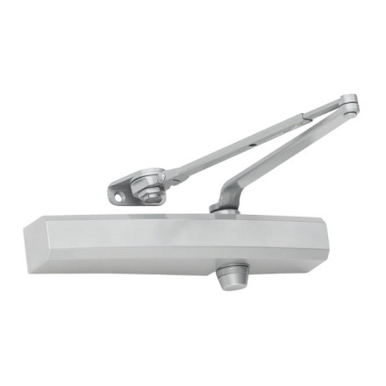
Pull Side and Push Side Mounts
L Screw pack information is on page 4.
Opening the regulation valves too far may result in the closer
leaking oil! This may result in closer and property damage, and
personal injury.
FOLLOW ALL INSTRUCTIONS CAREFULLY.
DO NOT USE THE CLOSER AS A DOOR STOP!
An auxiliary stop is recommended at the hold-open point or where
the door cannot swing 180º.
Pull Side 180° Mount (see page 2)
Push Side 110° Mount (see page 3)
1450 Track Series
PARTS
CAUTION
Left hand
door
Right hand door
Customer Service
1-877-671-7011
Improper installation or regulation may result in personal injury
Hold open track arms must NOT be installed on fire rated
Choose installation type
Hinge
edge of
door
Right hand
door
Hinge
edge of
door
Left hand door
1
Adjustable wrench
Phillips Head Screwdriver
Servicio al cliente
WARNING
or property damage.
Follow all instructions carefully.
For questions, call LCN at 877 - 671 - 7011.
doors.
Installation Instructions
TOOLS
B\cx" Hex Wrench
Z\," Drill Bit
C\cx" Hex Wrench
Service à la clientèle
www.allegion.com/us
Advertisement

Subscribe to Our Youtube Channel
Related Manuals for LCN 1450 Track Series


Summary of Contents for LCN 1450 Track Series
- Page 1 This may result in closer and property damage, and Follow all instructions carefully. personal injury. For questions, call LCN at 877 - 671 - 7011. FOLLOW ALL INSTRUCTIONS CAREFULLY. Hold open track arms must NOT be installed on fire rated DO NOT USE THE CLOSER AS A DOOR STOP! doors.
- Page 2 Pull Side 180° Mount Mounting Hole Dimensions Right hand (RH) shown throughout instructions. Left hand (LH) opposite. Frame 4 Z\zn" 21 C\v" 1" Hinge center line 6" 1 C\zn" Door C\v" 12" Measure from hinge center line and mark drilling holes. Install closer onto door using fasteners provided.
- Page 3 Push Side 110° Mount Mounting Hole Dimensions Left hand (LH) shown throughout instructions. Right hand (RH) opposite. Frame 5 Z\," 5 C\," 9 C\v" 5 C\," Hinge M\," Door center line Stop Header 2 M\," 1 C\v" Center Line of Track C\v"...
- Page 4 Closer Valve Adjustment Check closing time, and adjust closer if needed. c. Latch Speed- this controls door speed during the last few degrees of door closing. CAUTION 3. Turn the valves clockwise to decrease door speed, and counterclockwise to increase door speed. The latch speed and Opening the regulation valves (described below) too main speed should be adjusted together.
- Page 5 Esto puede Siga todas las instrucciones con atención. ocasionar daños en el mecanismo de cierre y materiales, y En caso de duda, llame a LCN al 877 - 671 - 7011. lesiones personales. SIGA TODAS LAS INSTRUCCIONES CON ATENCIÓN.
- Page 6 Soporte de 180° en el lado para empujar Dimensiones del orificio de montaje Se muestra la apertura hacia la derecha (RH) a lo largo de las instrucciones. El procedimiento para apertura hacia la izquierda (LH) es opuesto. Marco 4 Z\zn" 21 C\v"...
- Page 7 Push Side 110° Mount Dimensiones del orificio de montaje Se muestra la apertura hacia la izquierda (LH) a lo largo de las instrucciones. El procedimiento para apertura hacia la derecha (RH) es opuesto. Marco 5 Z\," 5 C\," 9 C\v" 5 C\,"...
- Page 8 Ajuste de la válvula del mecanismo de cierre Compruebe el tiempo de cierre y ajuste el mecanismo de cierre 4. Velocidad principal- controla la velocidad de la puerta durante de ser necesario. la mayor parte del movimiento de cierre. a. Velocidad del pasador- esto controla la velocidad de la PRECAUCIÓN puerta durante los últimos grados del cierre.
- Page 9 Suivez attentivement toutes les instructions. dommages matériels et des blessures. Pour toute question, appelez LCN au 877 - 671 - 7011. SUIVEZ ATTENTIVEMENT TOUTES LES INSTRUCTIONS. Les bras de retenue NE doivent PAS être installés sur les ÉVITEZ D'UTILISER LE DISPOSITIF DE FERMETURE COMME...
- Page 10 Montage côté tiré 180° Dimensions des trous de montage Montage à droite (MD) illustré tout au long de ces instructions. Le montage à gauche (MG) se fait de manière opposée. Cadre 4 Z\zn po 21 C\v po 1 po Axe central de la charnière 6 po 1 C\zn po...
- Page 11 Push Side 110° Mount Dimensions des trous de montage Montage à gauche (MG) illustré tout au long de ces instructions. Le montage à droite (MD) se fait de manière opposée. Cadre 5 Z\, po 5 C\, po 9 C\v po 5 C\, po Axe central M\, po...
- Page 12 Réglage de la soupape du dispositif de fermeture Vérifiez le temps de fermeture et réglez le dispositif de fermeture 3. Retenue - contrôle la vitesse d'ouverture de la porte lorsque au besoin. l'angle s'approche de 90°. N'utilisez pas de butoir. a.
Need help?
Do you have a question about the 1450 Track Series and is the answer not in the manual?
Questions and answers