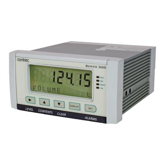
Contrec 515 Operation Manual
Flow computer single tank monitor for analog level sensors
Hide thumbs
Also See for 515:
- Operation manual (112 pages) ,
- Operation manuals (85 pages) ,
- Operation manual (88 pages)

Related Manuals for Contrec 515


Summary of Contents for Contrec 515
- Page 1 Model 515 Flow Computer Operation Manual LM02 Application Single Tank Level Monitor Analog Level Sensors 28 April 2021...
- Page 2 Should any questions arise which cannot be answered specifically by this manual, they should be directed to Contrec Ltd for further detailed information and technical assistance. Contrec Ltd will not accept any liability for either direct or consequential damages resulting from the use or misapplication of the contents of this manual.
- Page 3 Operating & Storage Temperature Operating: If a heater is being used, DO NOT isolate the instrument in temperatures below -20°C. Storage: DO NOT store the equipment below -20°C. 515 LM02 - 28 April 2021 515 LM02 - 28 April 2021...
- Page 4 Instrument Disposal Contrec instrumentation should not be thrown into the general waste system. If within EU member states, this instrument should be disposed of according to the guidelines set by the WEEE (Waste Electrical and Electronic Equipment) directive 2012/19/EU.
- Page 5 Logic Output Connection Control Relays (Alarms) RC Network for Interference Suppression Communications COM-1 RS-232 Port COM-2 RS-485 Port Option COM-2 Ethernet Port Option Mains Connection Earthing and Shielding Disconnection Device Maintenance Instructions Battery Replacement Battery Type 515 LM02 - 28 April 2021...
- Page 6 Error Messages Warning Messages Alarm Messages 6 Communications Overview Hardware Interconnection Protocols Simple ASCII Protocol Requests Format Instrument Responses Corrupted or Invalid Requests Modbus RTU Protocol List of Data Registers Printer Protocol Types of Printouts 515 LM02 - 28 April 2021...
- Page 7 Appendix B Model Numbers Product Codes Custom Version Codes Application Information Code Appendix C Units of Measurement Available Units of Measurement Appendix D Ethernet Port & Setup Ethernet Port Router Setup Configuring DataMod Index 515 LM02 - 28 April 2021...
- Page 8 515 LM02 - 28 April 2021...
-
Page 9: Table Of Contents
Output 4-20 mA Connection Diagram Output Logic Connection Diagram Relay Connection Diagram RS-485 Interface Connections Logged Data Display Methods Calibration Menu Tree Sheet 1 Calibration Menu Tree Sheet 2 RS-232 Cable Connections to a Computer RS-485 Connections 515 LM02 - 28 April 2021... - Page 10 515 LM02 - 28 April 2021...
- Page 11 • Backlit display Overview The 515 LM02 application monitors and measures the level of product in a single tank. The instrument uses the 4-20mA signal from a wide range of level sensors, including pressure transmitters, ultrasonic sensors and capacitance probes.
- Page 12 Main Menu Default Variable Variables Units Type Product Volume Rate Product Level Rate Volume Full % Rate Product Mass Rate Refer to Available Units of Measurement on page 74 for the list of available units. 515 LM02 - 28 April 2021...
- Page 13 The software is a Windows based program that is freely available from the download section of the Contrec website. The program can be used to create a custom version of an existing application to be saved for backup purposes and/or to generate a PDF of configuration report for record keeping.
- Page 14 Properly shielded and grounded cables and connectors must be used in order to meet FCC emission limits. Contrec Ltd is not responsible for any radio or television interference caused by using other than recommended cables and connectors or by unauthorized changes or modifications to this equipment.
- Page 15 BR2032 and CR2032 manufactured by Voltage 8 to 24 volts DC, programmable Panasonic or Sony Current 70 mA @ 24 V, 120 mA @ 12 V maximum Battery Life 5 years (typical) Protection Power limited output 515 LM02 - 28 April 2021...
- Page 16 0.8 volts maximum 4-20 mA Output Supply 9 to 30 volts DC external Resolution 0.05% full scale Accuracy 0.05% full scale (20C) 0.1% (full temperature range, typical) Important: Specifications are subject to change without notice. 515 LM02 - 28 April 2021...
- Page 17 The standard mounting procedure is panel mounting in a cutout that is 139 mm wide by 67 mm high. Two side clips secure the unit into the panel. Figure 2 shows the panel mounting requirements for the 515 instrument. Side View...
-
Page 18: Rear Panel Connections - Original
4 (terminals 34-35) share Relay Common 3-4 (terminal 36). Note: On these option cards the 6 way relay terminal block is ORANGE. Figure 5 shows the new option card with the RS-485 port (terminals 19-21). 515 LM02 - 28 April 2021... -
Page 19: Rear Panel Connections - New Rs-485 Version
Figure 4 Rear Panel Connections - New RS-485 Version Figure 5 shows the new option card with the optional Ethernet port in place of RS-485 port (terminals 19-21). Figure 5 Rear Panel Connections - New Ethernet Version 515 LM02 - 28 April 2021... - Page 20 UL/CSA approved cabling with supplementary insulation and a current capacity suitable for the connected circuit. (0.75mm², 6A current capacity is sufficient). Use copper conductors only. The maximum current must be <5A as stated in the Specifications. 515 LM02 - 28 April 2021...
-
Page 21: Externally Powered Voltage Transmitter
Terminal Designations on page 10 for specific terminal numbers for this application. Signal Analog Input (AINPn) Transmitter Shield Figure 6 Externally Powered Voltage Transmitter Connect internally powered voltage transmitters as shown in Figure 7. 515 LM02 - 28 April 2021... -
Page 22: Internally Powered Voltage Transmitter
Logic Input Connection These input(s) are designed to be connected to CMOS, TTL, open collector signals or a voltage free contact switch. A minimum activation time of 300ms is required to guarantee reading of an input. 515 LM02 - 28 April 2021... - Page 23 27 (+) and 28 (-), output channel 2 uses terminals 29 (+) and 30 (-). Maximum Load Resistance = (Supply-9) / 0.02 ohms 4-20 mA DC supply Output 9...24V (OUTn) Load Shield Figure 10 Output 4-20 mA Connection Diagram 515 LM02 - 28 April 2021...
- Page 24 The output characteristics of the relays are: Maximum Voltage 30 volts DC or 250 volts AC Maximum Current 3 A for EMR, 1.5A for SSR Note: Solid state relays use AC voltage only. 515 LM02 - 28 April 2021...
- Page 25 The basic principle of the operation is that the capacitor prevents a series of sparks arcing across the contact as the contact breaks. The series resistor limits the current through the contact when the contact first makes. Communications The communication protocols are described in Communications page 51. 515 LM02 - 28 April 2021...
- Page 26 Figure 13 shows the connection of several instruments to a computer using the RS-485 port. Host Twisted Pair Computer Load 120 ohms Comms 19 20 21 19 20 21 Instrument Instrument Figure 13 RS-485 Interface Connections 515 LM02 - 28 April 2021...
- Page 27 If mounted in an ExD enclosure, before proceeding, refer to the ExD manual for further information. This work may need to be scheduled and carried out in accordance with the local electrical Code of Practice. 515 LM02 - 28 April 2021...
- Page 28 2. Conformal coated “C” version - Type BR2032, manufacturer Panasonic ONLY. 3. Non Conformally coated versions :- BR2032, CR2032, Sony or Panasonic ONLY. *Issue 7 option card can be identified with 6 way (31-36) ORANGE relay connector. 515 LM02 - 28 April 2021...
- Page 29 Press the key to display the current tank level. If there is more than LEVEL LEVEL one level variable, press or hold the key to display the other level LEVEL variables in turn. 515 LM02 - 28 April 2021...
- Page 30 Hold the key to display the Model information as described in Model Information on page 23. CAL MENU Hold the key to enter Calibration View mode as described in Calibration View Mode on page 28. 515 LM02 - 28 April 2021...
- Page 31 Operation Detail and Basic Menu The 515 instrument has the option to switch the main menu from the full Detail menu to a Basic menu. The Detail menu includes all of the main menu variables and the HOLD SET sub menu items as listed above. In the Basic menu only the application or operator essential main menu variables are shown.
- Page 32 … … DISPLAY Hold … show the values for Variable 2 a log entry Variable 1 DISPLAY and press Hold Error code display the main menu variables Figure 14 Logged Data Display Methods 515 LM02 - 28 April 2021...
- Page 33 Reset to start the printing of the configuration report. The report will be in a similar format to the report generated by the 500 Program Manager. Press at any time to exit from the Model information. 515 LM02 - 28 April 2021...
- Page 34 Once in edit mode the Set indicator will illuminate and the setpoint values are changed in exactly the same way as in calibration set mode. Press the key again to exit edit mode and return to the alarm item. 515 LM02 - 28 April 2021...
- Page 35 Alarm 1 Acknowledged Alarm led solid, Relay deactivated Alarm 2 Acknowledged Lowest priority The key indication that the alarm being scrolled on the display is acknowledged or not is the status of the Alarm led. 515 LM02 - 28 April 2021...
- Page 36 Operation 515 LM02 - 28 April 2021...
- Page 37 “programmable” parameters, but the correct password must be entered to change the password-protected parameters. Likewise, the CAL switch (Logic Input 4) must be used to enter Calibration Set mode to change the CAL switch protected parameters. 515 LM02 - 28 April 2021...
- Page 38 To select the next digit, press 6. Press or use the CAL switch on Logic Input 4 (if “Cal switch protected” items exist) to accept the password and proceed. 7. Proceed and observe the access confirmations. 515 LM02 - 28 April 2021...
- Page 39 “Cal switch protected” items exist, the CAL switch can be closed for two seconds. The instrument makes two beeps and cancels the Cal and Set indicators. Alarm 515 LM02 - 28 April 2021...
- Page 40 Units of Measurement The calibration of some parameters is based on the units that are defined for the relevant variables. These units of measurement can been viewed in the UNITS menu in calibration below. 515 LM02 - 28 April 2021...
- Page 41 To assist in keeping an audit trail of the program settings and changes made via the front panel, the 515 instrument provides the ability to print the configuration to a local printer if one has been connected and assigned to one of the 515 communication ports.
-
Page 42: Calibration Menu Tree Sheet
PT-MAX PT-MAX selection CONV TYPE LINEAR NON-LIN POINT HYST NO-PTS DELAY INP-01 INP-n OUT-01 ALRM3 OUT-n selection TYPE POINT HYST DELAY ALRM4 selection TYPE POINT HYST DELAY Figure 15 Calibration Menu Tree Sheet 1 515 LM02 - 28 April 2021... -
Page 43: Calibration Menu Tree Sheet
I/O assignment position to move to the next I/O assignment in the submenu (eg pressing on ALRM1 will move you to ALRM2 if it exists) Figure 16 Calibration Menu Tree Sheet 2 515 LM02 - 28 April 2021... - Page 44 LEVEL or PRESSUR. D-CAL The calibration density is the density of the product at the time of the tank unit calibration. This parameter is required only when a pressure sensor is selected. 515 LM02 - 28 April 2021...
- Page 45 2 as the minimum point. If the source signal is 20 mA at a maximum level of 5m, enter 5 as the maximum point. If the sensor is inverted the value entered for the minimum point will be greater than the value entered for the maximum point 515 LM02 - 28 April 2021...
- Page 46 Seconds to reach 90% Seconds to reach 99% of full swing of full swing The input filter range is from 0 to 99. A setting of 0 (zero) means that there is no filtering. 515 LM02 - 28 April 2021...
- Page 47 Non-linear. Enter the number of conversion points required for the normalised level to volume tank strapping table. Press to select a number between 1 and 20 for the number of conversion points. 515 LM02 - 28 April 2021...
- Page 48 (1.0). Only the points between 0 and 1 are required to be entered and should be entered in ascending order. You can press the key to skip the non-linear points and go to the DISPLAY next item. 515 LM02 - 28 April 2021...
- Page 49 It can be used to control the amount of product in a tank by activating a pump or valve for refilling the tank. Press to select the variable that is required as an output. 515 LM02 - 28 April 2021...
- Page 50 The alarm switches “on” whenever an alarm condition exists. The alarm switches “off” when the alarm condition no longer exists. For further details, refer to Operation of Alarms on page 25. 515 LM02 - 28 April 2021...
- Page 51 BD-NO — Band Alarm, Normally Open contacts • BD-NC — Band Alarm, Normally Closed contacts • AL-NO — Equipment Alarm, Normally Open contacts • AL-NC — Equipment Alarm, Normally Closed contacts Press to select the type of alarm required. 515 LM02 - 28 April 2021...
- Page 52 Ethernet connection requires COM-2 setting to be: RTU (Modbus), 19200 Baud rate, even parity and 1 stop bit. • COM-3 Port- A special communications port that is only applicable to some applications. 515 LM02 - 28 April 2021...
- Page 53 1 or 2 stop bits. DATA The Modbus RTU data format for the 2-register (4-byte) values can be set as either floating point or long integer values. to select FLOAT or INTEGER. 515 LM02 - 28 April 2021...
- Page 54 In this case, you should set the current time and date so that the instrument continues to log data at the correct times. 515 LM02 - 28 April 2021...
- Page 55 YEAR LOGS Set the number of Yearly Logs to appear on the printed log report. The yearly log entry occurs at 00 hours and 00 minutes on the first day of the year. 515 LM02 - 28 April 2021...
- Page 56 Press to select the default variable display. SUPPLY VOLT The instrument provides a power-limited supply for external transducers. Press to set the transducer supply voltage between 8 and 24 volts DC as required. 515 LM02 - 28 April 2021...
- Page 57 10 seconds, the display backlight switches off to save power. The backlight switches on when a key is pressed. Select the backlight timeout mode as required. Press to select ENABLE or DISABLE. 515 LM02 - 28 April 2021...
- Page 58 You can display the actual DC output supply voltage, which may help SUPPLY with troubleshooting. If the actual supply voltage is lower than the preset value (refer to General Setup Parameters on page 46) it may indicate that the output is overloaded. 515 LM02 - 28 April 2021...
- Page 59 Power Supply is Low The input and/or output power supply voltage is too low, ensure that: (a) input power supply voltage is within the specified range (b) output power supply is not overloaded. 515 LM02 - 28 April 2021...
- Page 60 The alarm condition, as defined for relay alarm 1 in the ALARMS section of calibration, is present. Alarm 2 is Active The alarm condition, as defined for relay alarm 2 in the ALARMS section of calibration, is present. 515 LM02 - 28 April 2021...
-
Page 61: Rs-232 Cable Connections To A Computer
Computers use either a DB9 or a DB25 connector, and the connections to each type are shown in Figure 17. Instrument Computer/Printer Common Optional Optional DB25 Figure 17 RS-232 Cable Connections to a Computer 515 LM02 - 28 April 2021... - Page 62 • - Modbus RTU available for all ports • - Printer Protocol available for COM-1 and COM-2 • NONE - If a port is not being used, set the protocol to NONE. 515 LM02 - 28 April 2021...
- Page 63 • ASCII - In this ASCII protocol each command and response is a string of ASCII characters. This proprietary protocol is developed by Contrec to allow for simple information interchange. The main advantages of this mode are that it allows extended time intervals to occur between characters without causing a timeout error and that messages can be sent and monitored easily with a simple ASCII terminal.
- Page 64 Instrument Responses The instrument response time to any enquiry is not more than 300 ms. The responses from the instrument are in the following format: 515 LM02 - 28 April 2021...
- Page 65 Return all variables :RVD? Return the default variable :RV0? … Return the specific variable. The numbers relate to the :RV9? position in the variables menu. For example, V0 is Energy, V1 is Power and so on. 515 LM02 - 28 April 2021...
- Page 66 The log request asks the instrument how many logs will be included in a printed log report. These are the values described in Time Settings and Data Logging on page 54. Command Description :RLR? Return the number of log records (non- timebased logging) 515 LM02 - 28 April 2021...
- Page 67 Return the general information about the instrument such as Model number, Application number, Version and Serial numbers etc. These items are returned as a block in the same format as shown on the display in the “Model Info” menu. 515 LM02 - 28 April 2021...
- Page 68 Modbus RTU (remote terminal unit) is an industry standard protocol that allows the instrument to be easily interfaced to other communication devices. The instrument implements the Modbus protocol as detailed in the Modicon Modbus Protocol Reference Guide PI-MBUS-300 Rev J (June 1996). 515 LM02 - 28 April 2021...
- Page 69 Read data register(s) Obtain the content of one or more 2-byte data registers. Preset data register Preset one 2-byte data register. Read status register Obtain the content of 1-byte status register. Preset data register(s) Preset one or more 2-byte data registers. 515 LM02 - 28 April 2021...
- Page 70 “register 1” in this case has “address 0” and so on. Current and Logged Process Data This block of registers is available for the retrieval of current or logged process data with its matching time and date information. 515 LM02 - 28 April 2021...
- Page 71 Note: The Floating Point variable is represented in IEEE-754 Floating Point 4-byte format and requires two 2-byte data registers: IEEE-754 Modicon Registers 1st byte low byte (register X) 2nd byte high byte (register X) 515 LM02 - 28 April 2021...
- Page 72 0 to 15 Binary representation of logic inputs B0 = 0/1 (LSB)input 1 activated/deactivated B1 = 0/1input 2 activated/deactivated B2 = 0/1input 3 activated/deactivated B3 = 0/1input 4 activated/deactivated Operation Mode Representation of operation mode 0 = Idle/LocalIdle state 515 LM02 - 28 April 2021...
- Page 73 Unused inputs are configured as 4-20mA. * I = Integer (2 bytes) (Holding Registers) † DT = Data Type of 2-register (4 byte) values can be set as Floating Point or Long Integer values 515 LM02 - 28 April 2021...
- Page 74 A customized printout can be provided which can have up to 4 header lines and 3 footer lines. It is also possible to include or exclude each main menu items on the printout. If any customizing of the printout is required discuss this with the distributor. 515 LM02 - 28 April 2021...
- Page 75 The printout will have the time and date stamp corresponding to when the log was taken. After the print has been initiated there will be the opportunity to scroll to view another log entry and print again. 515 LM02 - 28 April 2021...
- Page 76 -------------------------------------------- <separation line> Log No. Date & Time & Status Variable unit value Variable unit value etc. -------------------------------------------- <separation line> Log No. Date & Time & Status Variable unit value Variable unit value 515 LM02 - 28 April 2021...
- Page 77 Some printers will also transmit an Xoff character in response to other events such as printer being off-line, print head not engaged or power being removed. The specific behaviour of the printer being used should be noted. 515 LM02 - 28 April 2021...
- Page 78 When a communications timeout error has been activated the message COMMS TIMEOUT will be scrolled once, the request to print will be cleared and the instrument will return to its normal mode. 515 LM02 - 28 April 2021...
- Page 79 The 500 Series Program Manager (500-PM software) is a Windows based Software program that is freely available from the download section of the Contrec website. The program is a comprehensive configuration tool and resource centre that can be used to tailor an instrument to suit specific application needs including program settings, units of measurement, custom tags/text, access levels and more.
- Page 80 515 LM02 - 28 April 2021...
- Page 81 Note: The first character represents the CPU installed (factory use only). The remaining 6 characters only MODEL represent hardware that affects the operation. Note: Example full product part number is 515.111USC-LM02 (This is the number used for placing orders). 515 LM02 - 28 April 2021...
- Page 82 Custom Version Codes Code Description Factory Default Application Contrec Systems Pty. Ltd. Melbourne Australia Contrec Limited. West Yorkshire UK Origin Code Identifies Contrec - USA, LLC. Pelham AL 35124 USA Distributor Flowquip Ltd. Halifax UK etc. English (Default) German Dutch User Language...
- Page 83 For example, is an instrument with FINP1 (frequency input 1) assigned to a flow input, AINP1 assigned to a temperature input and AINP2 assigned as a pressure input. The other inputs are not used. 515 LM02 - 28 April 2021...
- Page 84 E+0, E+3, E+6 (scaling for unitless variable) Length (Level) m, mm, cm, INCH, FOOT Velocity m/s, m/M, m/h,ft/s, ft/M, ft/h Length K-Factor P/m, P/cm, P/INCH, P/FOOT Area , ft Ratio General Input Pressure, Temperature, Density, Length (Level), Factor 515 LM02 - 28 April 2021...
- Page 85 Ethernet network. In some installations you will need to speak with your Network administrator in order to correctly set up your Network. Applications, such as Datamod (available via Contrec), can communicate over the Ethernet network to perform remote monitoring and Data Logging operations.
- Page 86 515 LM02 - 28 April 2021...
- Page 87 ASCII protocol connections alarm communication back panel communications backup electrical program input Program Manager mains basic menu output battery control modes failed customer version codes life customizing a printout battery replacement battery type daily logging 515 LM02 - 28 April 2021...
- Page 88 LEDs monthly weekly yearly glossary main menu hardware connections basic and detailed hourly logging main menu items hysteresis, alarm mains connections maintenance 515 LM02 - 28 April 2021...
- Page 89 Modbus RTU output printer connections pulse output 4-20mA pulse outputs menu real-time clock override error condition rear panel relay outputs relays, alarm panel RESET key LEDs responses, instrument mounting RS-232 COM-1 port 16, 42 rear 515 LM02 - 28 April 2021...
- Page 90 TOTAL key unit tag units menu upload application software variable, default version, customer view data logs 21, 22 warnings watchdog timer (WDT) weekly logging 515 LM02 - 28 April 2021...
Need help?
Do you have a question about the 515 and is the answer not in the manual?
Questions and answers