Contrec 515 Operation Manual
Flow computer
Hide thumbs
Also See for 515:
- Operation manual (112 pages) ,
- Operation manuals (85 pages) ,
- Operation manual (92 pages)

Related Manuals for Contrec 515


Summary of Contents for Contrec 515
- Page 1 Model 515 Flow Computer Operation Manual BS01 Application Secure Dual Stage Batch Controller Frequency Flowmeters 15 August 2021...
- Page 2 Should any questions arise which cannot be answered specifically by this manual, they should be directed to Contrec Ltd for further detailed information and technical assistance. Contrec Ltd will not accept any liability for either direct or consequential damages resulting from the use or misapplication of the contents of this manual.
- Page 3 Operating & Storage Temperature Operating: If a heater is being used, DO NOT isolate the instrument in temperatures below -20°C. Storage: DO NOT store the equipment below -20°C. 515 BS01 - 15 August 2021 515 BS01 - 15 August 2021...
- Page 4 Instrument Disposal Contrec instrumentation should not be thrown into the general waste system. If within EU member states, this instrument should be disposed of according to the guidelines set by the WEEE (Waste Electrical and Electronic Equipment) directive 2012/19/EU.
-
Page 5: Table Of Contents
Logic Input Connection Outputs 4-20 mA Output Connection Digital Output Connection Control Relays (Alarms) RC Network for Interference Suppression Communications COM-1 RS-232 Port COM-2 RS-485 Port Option COM-2 Ethernet Port Option Mains Connection Earthing and Shielding 515 BS01 - 15 August 2021... - Page 6 Changing the Instrument Settings Program Backup & Reports Backup via 500 Series Program Manager Printing Configuration Report Upload and Clone of Application Software Calibration Menu Tree Instrument Settings Units of Measurement Parameters Inputs Outputs Alarms Communications 515 BS01 - 15 August 2021...
- Page 7 Appendix A Glossary Glossary Appendix B Model Numbers Product Codes Custom Version Codes Application Information Code Appendix C Ethernet Port & Setup Ethernet Port Connecting 515 Ethernet to Networks/Routers Connecting DataMod via Ethernet Index 515 BS01 - 15 August 2021...
- Page 8 515 BS01 - 15 August 2021...
- Page 9 Batch Operation with Manual or Automatic Reset Batch Operation with Automatic Restart Calibration Menu Tree Sheet 1 Calibration Menu Tree Sheet 2 RS-232 Cable Connections to a Computer RS-485 Connections DataMod - Modbus Connection Settings 515 BS01 - 15 August 2021...
- Page 10 515 BS01 - 15 August 2021...
-
Page 11: Introduction
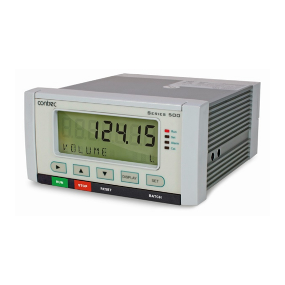
Backlit display with LCD backup Overview The 515 BS01 application is a secure dual stage batch controller for reliable measurement of preset quantities using a volume frequency input. The instrument can be set to accept a valid ID-Tag via ‘iButton’ or RFID reader on the serial port and/or prompt for connection of a permissive before a batch can be commenced. -
Page 12: Analog Inputs As User Code
The User Code is logged/printed with the other main menu items and can serve, for example, as a Tank ID/Code on a delivery docket. Note: the higher numbered analog inputs have priority over lower numbered ones. 515 BS01 - 15 August 2021... -
Page 13: Displayed Information
There are two communication ports available as follows: • COM-1 RS-232 port • COM-2 RS-485 port (optional) or Ethernet (optional) The ports are available for remote data reading, printouts and for initial application loading of the instrument. 515 BS01 - 15 August 2021... -
Page 14: Isolated Outputs
The software is a Windows based program that is freely available from the download section of the Contrec website. The program can be used to create a custom version of an existing application to be saved for backup purposes and/or to generate a PDF of configuration report for record keeping. -
Page 15: Specialised Uses
The instrument also checks for simultaneous pulses, missing pulses on channel 1 and missing pulses on channel 2. If more than two errors, of one of these fault types, occur within 2000 pulses the instrument will raise a quadrature input exception. 515 BS01 - 15 August 2021... - Page 16 Operation of this equipment in a residential area is likely to cause harmful interference, in which case the user will be required to correct the interference at his own expense. 515 BS01 - 15 August 2021...
- Page 17 Introduction Properly shielded and grounded cables and connectors must be used in order to meet FCC emission limits. Contrec Ltd is not responsible for any radio or television interference caused by using other than recommended cables and connectors or by unauthorized changes or modifications to this equipment.
- Page 18 Introduction 515 BS01 - 15 August 2021...
-
Page 19: Specifications Specification Table
Renata only - For conformal coated ‘C’ version, type BR2032 manufactured by Panasonic only - For non-conformal coated versions, type BR2032 and CR2032 manufactured by Panasonic or Sony Battery Life 5 years (typical) 515 BS01 - 15 August 2021... - Page 20 Programmable: 10 , 20, 50, 100, 200 or 500ms 4-20 mA Output Supply 9 to 30 volts DC external Resolution 0.05% full scale Accuracy 0.05% full scale (20C) 0.1% (full temperature range, typical) Important: Specifications are subject to change without notice. 515 BS01 - 15 August 2021...
-
Page 21: Installation & Maintenance
The standard mounting procedure is panel mounting in a cutout that is 139 mm wide by 67 mm high. Two side clips secure the unit into the panel. Figure 2 shows the panel mounting requirements for the 515 instrument. Side View... -
Page 22: Electrical Connection
Note: On these option cards the 6 way relay terminal block is ORANGE. Figure 4 shows the new option card with the RS-485 port (terminals 19-21). Figure 4 Rear Panel Connections - New RS-485 Version 515 BS01 - 15 August 2021... -
Page 23: Terminal Designations
E Mains ground Term 36 only available on AC power in 100- RC Relay common 3-4 N Mains neutral new style option card MAINS 240VAC A Mains active RS232 COM-1 port 9-pin serial port 515 BS01 - 15 August 2021... -
Page 24: Terminal Wiring Insulation
Electrical Code of Practice as dictated by the Authority Having Jurisdiction (AHJ). The terminal designations (L/N/E) are clearly indicated just above the mains input connector on the rear panel of the instrument. 515 BS01 - 15 August 2021... -
Page 25: Inputs
Shield Reed Relay Switch Frequency Input (FINPn) Signal Ground 18 Shield Coils - with 15mV minimum amplitude (typical) Frequency Input (FINPn) Signal Ground Shield Namur Proximity Switch Vo +8V DC Frequency Input (FINPn) Shield 515 BS01 - 15 August 2021... -
Page 26: Analog Input Connections
Logic Input Connection These inputs are designed to be connected to CMOS, TTL, open collector signals or a voltage free contact switch. A minimum activation time of 300ms is required to guarantee reading of an input. 515 BS01 - 15 August 2021... -
Page 27: Outputs
Figure 9 shows the connections for a 4-20 mA output. Output channel 1 uses terminals 27 (+) and 28 (-), output channel 2 uses terminals 29 (+) and 30 (-). Maximum Load Resistance = (Supply-9) / 0.02 ohms 515 BS01 - 15 August 2021... -
Page 28: Digital Output Connection
27 (+) and 28 (-). Output channel 2 uses terminals 29 (+) and 30 (-). Vo +8...24V DC External Load Resistor 10K Logic Input Open Pulse Output Collector (OUTn) Output DC Ground Shield Figure 10 Output Pulse Connection Diagram 515 BS01 - 15 August 2021... -
Page 29: Control Relays (Alarms)
Note: Solid state relays (SSR) use AC voltage only. Relay 1 RC Relay 1-2 Common Control Supply Relay 2 Control Relay 3 Alarm/Load Relay 4 Alarm/Load Supply Relay 3-4 Common Figure 11 Relay Connection Diagram 515 BS01 - 15 August 2021... -
Page 30: Rc Network For Interference Suppression
The basic principle of the operation is that the capacitor prevents a series of sparks arcing across the contact as the contact breaks. The series resistor limits the current through the contact when the contact first makes. 515 BS01 - 15 August 2021... -
Page 31: Communications
Figure 12 shows the connection of several instruments to a computer using the RS-485 port. Twisted Pair Host Computer Load 120 ohms Comms 19 20 21 19 20 21 Instrument Instrument Figure 12 RS-485 Interface Connections 515 BS01 - 15 August 2021... -
Page 32: Com-2 Ethernet Port Option
If mounted in an ExD enclosure, before proceeding, refer to the ExD manual for further information. This work may need to be scheduled and carried out in accordance with the local electrical Code of Practice. 515 BS01 - 15 August 2021... - Page 33 2. Conformal coated “C” version - Type BR2032, manufacturer Panasonic ONLY. 3. Non Conformally coated versions :- BR2032, CR2032, Sony or Panasonic ONLY. *Issue 7 option card can be identified with 6 way (31-36) ORANGE relay connector. 515 BS01 - 15 August 2021...
- Page 34 Installation & Maintenance 515 BS01 - 15 August 2021...
- Page 35 There are several categories of information that the instrument can display: • Totals • Rates • Batch preset values • Density preset value • Instrument settings For each total, there is an associated rate as follows: Total Rate Volume Volume Flowrate Mass Mass Flowrate 515 BS01 - 15 August 2021...
- Page 36 Continue to BATCH BATCH hold for two seconds to enter edit mode for the preset if access is authorised. Pressing the key briefly displays the accumulated total. BATCH 515 BS01 - 15 August 2021...
- Page 37 Model Menu information as described in Model Information on page 30. CAL MENU Only shown in Detail Hold the key to enter Calibration View Menu mode as described in Calibration View Mode page 40. 515 BS01 - 15 August 2021...
- Page 38 Operation Detail and Basic Menu The 515 instrument has the option to switch the main menu from the full Detail menu to a Basic menu. The Detail menu includes all of the main menu variables and the HOLD SET sub menu items as listed above. In the Basic menu only the application or operator essential main menu variables are shown.
- Page 39 The instrument displays the most recent log record first. The log record number and corresponding delivery number are shown, for example LR-001 and DEL 1236. 1236 LR-001 3. Use the keys to scroll to the delivery number or log record of interest. 515 BS01 - 15 August 2021...
- Page 40 ABC123 left. Both items are entered when the instrument application software is initially loaded. If the unit tag is not used the default tag, , will be used. UNIT 515 BS01 - 15 August 2021...
- Page 41 This instrument can operate in the following Batch operation modes: • PRESET • ON-OFF • UNLOAD Preset Mode If the batch mode is PRESET the prestop and shut-off points are determined by the instrument. 515 BS01 - 15 August 2021...
- Page 42 Before a batch or delivery can be commenced it may be imperative that certain safety or security measures are in place. Interlocks, grounding connections, secure keys and identification devices can be used to prevent untrained or unauthorised personnel from operating the batch controller. 515 BS01 - 15 August 2021...
- Page 43 The instrument can be programmed to batch on either the Volume or Mass Total. The batch type is chosen via the ASSIGN BATCH parameter. Care should be taken when batching in Volume or Mass units, so that a vessel cannot be accidentally overfilled. 515 BS01 - 15 August 2021...
- Page 44 • If Auto Reset is enabled in the parameters section of calibration or the operation mode is programmed to UNLOAD, the batch total will automatically reset when the next delivery (batch) is started. 515 BS01 - 15 August 2021...
- Page 45 The Remote Stop input can also be used to reset the batch total by holding the logic input low for 2 seconds if the batch is already complete. For connection details, refer to Logic Input Connection on page 16. 515 BS01 - 15 August 2021...
- Page 46 The batch controller (if not in UNLOAD operation mode) can be programmed to operate in various ways including: • Manual Reset (manual start). • Automatic Reset (manual start). • Automatic Restart for continuous batches (PRESET mode only). 515 BS01 - 15 August 2021...
-
Page 47: Batch Operation With Manual Or Automatic Reset
Reached Reset Count Down Batch Total Count Up Relay 1 Relay 2 Slow Start Time Prestop Qty End of Batch End of Batch Pump Control Figure 13 Batch Operation with Manual or Automatic Reset 515 BS01 - 15 August 2021... -
Page 48: Batch Operation With Automatic Restart
Reached Count Down Batch Total Count Up Relay 1 Relay 2 Slow Start Time Prestop Qty Auto Restart End of Time Batch End of Batch Pump Control Figure 14 Batch Operation with Automatic Restart 515 BS01 - 15 August 2021... - Page 49 “programmable” parameters, but the correct password must be entered to change the password-protected parameters. Likewise, the CAL switch (Logic Input 4) must be used to enter Calibration Set mode to change the CAL switch protected parameters. 515 BS01 - 15 August 2021...
- Page 50 To select the next digit, press 6. Press or use the CAL switch on Logic Input 4 (if “Cal switch protected” items exist) to accept the password and proceed. 7. Proceed and observe the access confirmations. 515 BS01 - 15 August 2021...
- Page 51 “Cal switch protected” items exist, the CAL switch can be closed for two seconds. The instrument makes two beeps and cancels the Cal and Set indicators. Alarm 515 BS01 - 15 August 2021...
- Page 52 The calibration of some parameters is based on the units that are defined for the relevant variables. These units of measurement can been viewed in the UNITS menu in the Instrument Settings section below. 515 BS01 - 15 August 2021...
- Page 53 To assist in keeping an audit trail of the program settings and changes made via the front panel, the 515 instrument provides the ability to print the configuration to a local printer if one has been connected and assigned to one of the 515 communication ports.
-
Page 54: Calibration Menu Tree Sheet
DELAY OP-CTRL STOP FACT01 FACTn OP-RST No-SET BATCH selection OP-END SET-nn BATCH 4-20 mA PULSE DIRECT ACCES PT-MIN WIDTH PRESET BATCH PT-MAX PULSE O-RUN COMP DENS units Figure 15 Calibration Menu Tree Sheet 1 515 BS01 - 15 August 2021... - Page 55 I/O assignment position to move to the next I/O assignment in the submenu (eg pressing on ALRM1 will move you to ALRM2 if it exists) Figure 16 Calibration Menu Tree Sheet 2 515 BS01 - 15 August 2021...
- Page 56 YES, then press the key. The instrument makes three beeps to confirm the reset command. The message -RESET- PLEASE WAIT will be displayed as the instrument exits calibration mode and completes a full re-boot sequence. 515 BS01 - 15 August 2021...
- Page 57 Enter the value in the engineering units of the batch preset. S-STRT The batch slow start time determines when relay 2 activates after the start or resumption of a batch. Enter the value in seconds. 515 BS01 - 15 August 2021...
- Page 58 20% is considered invalid and will not be included in the calculations. Press to select ENABLE or DISABLE. STOP The function of the Stop key can be set to either Pause or Stop the delivery. Press to select PAUSE or STOP. 515 BS01 - 15 August 2021...
- Page 59 Enter the value in the engineering units of the assigned variable. Enter the fluid density preset that will be used for the mass calculations. DENS units Enter the value in the engineering units of the assigned variable. 515 BS01 - 15 August 2021...
- Page 60 For example if the cut-off is set to 0.01 Hz, and the measured flow stops, the instrument continues to display the flow rate for 100 seconds before it can determine that the flow has actually stopped. 515 BS01 - 15 August 2021...
- Page 61 This parameter is available for viewing and editing only when the correction type is set to Linear. The K-factor of the flowmeter is the number of pulses from the flowmeter per unit of volume (or mass). The K-factor cannot be 0 (zero). 515 BS01 - 15 August 2021...
- Page 62 This parameter is available for viewing and editing only when the correction type is set to Non-linear. FACT Enter the scaling factor for this correction point in the same units of measure as the single K-factor above. The correction factor cannot be 0 (zero). 515 BS01 - 15 August 2021...
- Page 63 (pulse output) type. Pulse output is usually used to drive remote counters. Set the pulse width (in milliseconds) as required by the remote counter. Press to set to: 10, 20, 50, 100, 200 or 500 ms. 515 BS01 - 15 August 2021...
- Page 64 “keep up” with the rate of total counts. You can use the output pulse factor to ensure that this maximum is not reached. The maximum pulse output frequency is determined by: 1000 ------------------------------------------------------- -Hz 2 pulse width in ms 515 BS01 - 15 August 2021...
- Page 65 Select a rate variable to assign to the alarm relay. Note: If the alarm type is set to “equipment alarm”, this relay assignment setting is ignored. Press to select the variable that is required as an alarm. 515 BS01 - 15 August 2021...
- Page 66 200 and toggle off below 200. However, if the hysteresis is set to 5, the value of the variable must fall below 195 to cancel the alarm. The alarm will reactivate only when the value again rises above 200. 515 BS01 - 15 August 2021...
- Page 67 The Parity bit helps to detect data corruption that might occur during transmission. The parity bit setting of the instrument must match the parity bit setting of the communication device that the instrument is connected to. Press to select EVEN, ODD, or NONE. 515 BS01 - 15 August 2021...
- Page 68 Therefore, after an interruption to the power supply, the instrument recommences normal operation although there will be no data recorded during the period without a power supply. 515 BS01 - 15 August 2021...
- Page 69 The Printer Protocol Report Type determines the nature of the printout from the REPORT PRINT - HOLD.SET prompt in the main menu. The following report types available in this instrument are: • REP-10 Preset number of latest logs Press to select Report Type. 515 BS01 - 15 August 2021...
- Page 70 Press to select the default variable display. SUPPLY VOLT The instrument provides a power-limited supply for external transducers. Press to set the transducer supply voltage between 8 and 24 volts DC as required. 515 BS01 - 15 August 2021...
- Page 71 Note: The user-defined tags can be entered into the instrument only by the manufacturer or the distributor. Press to select the Display Tags option as follows: • DEFAULT - the instrument displays the default (English) tags • USER - the instrument displays the user-defined tags. 515 BS01 - 15 August 2021...
- Page 72 If the wrong tag is entered it can be overwritten with the correct key or cleared by pressing and holding the key. RESET These authorisation codes can also be accessed and edited via Modbus communications, see Valid Authorisation Codes on page 81. 515 BS01 - 15 August 2021...
- Page 73 You can display the actual DC output supply voltage, which may help with troubleshooting. If the actual supply voltage is lower than the preset value (refer to General Setup Parameters on page 60) it may indicate that the output is overloaded. 515 BS01 - 15 August 2021...
- Page 74 (or pause) the flow. Leakage The leakage condition is detected when an amount greater than the Detected acceptable total is received without flow being initiated by the batch controller. 515 BS01 - 15 August 2021...
- Page 75 The system displays prompt messages as described in the following table: Prompt Messages Description Connect Permissive Connect permissive to proceed with batching. Validate ID Tag Validate ID Tag to proceed with batching. Press Run Key Press Run key to start batching. 515 BS01 - 15 August 2021...
- Page 76 Instrument Calibration 515 BS01 - 15 August 2021...
- Page 77 Common Optional Optional DB25 Figure 17 RS-232 Cable Connections to a Computer Note: The instrument requires a cable with straight-through connections. Do not use a null modem cable for RS-232 connection to a computer. 515 BS01 - 15 August 2021...
- Page 78 Note: The Printer Protocol is only available if the option with Real Time Clock is installed. Also a protocol cannot be assigned to more than one port at a time as described in Communications on page 57. 515 BS01 - 15 August 2021...
- Page 79 • iButton ID-TAG - This protocol allows an external “iButton LINK45” module to be connected to 515 instrument to read identification tags to ensure only authorised deliveries are made. • Printer - In the Printer protocol there is a selection of printer types.
- Page 80 Instrument Responses The instrument response time to any enquiry is not more than 300 ms. The responses from the instrument are in the following format: 515 BS01 - 15 August 2021...
- Page 81 Return the default Total and Rate :RV0? … Return the specific variable. The numbers relate to the :RV9? position in the variables menu. For example, V0 is Energy, V1 is Power and so on. 515 BS01 - 15 August 2021...
- Page 82 The log request asks the instrument how many logs will be included in a printed log report. These are the values described in Time Settings and Data Logging on page 58. Command Description :RLR? Return the number of log records (non- timebased logging) 515 BS01 - 15 August 2021...
- Page 83 Return the general information about the instrument such as Model number, Application number, Version and Serial numbers etc. These items are returned as a block in the same format as shown on the display in the “Model Info” menu. 515 BS01 - 15 August 2021...
- Page 84 For example, if the instrument received the following request variables message :A001:RVT? it will return only the header because there is no T option for the ‘Variables Request’ message. 515 BS01 - 15 August 2021...
- Page 85 The address of the instrument is programmable in the range from 1 to 247. Some addresses are reserved according to PI-MBUS-300 and have a special meaning: • 0 = Broadcast, no response required from slave devices • 248 to 255 Reserved 515 BS01 - 15 August 2021...
- Page 86 Slave device busy The slave is engaged in processing a long duration program command. The master should re-transmit the message later when the slave is free. 515 BS01 - 15 August 2021...
- Page 87 (register X) 3rd byte low byte (register X+1) 4th byte high byte (register X+1) This means that two data registers must be read or written to obtain, or preset, one data value. 515 BS01 - 15 August 2021...
- Page 88 02 - clear accumulated totals 03 - clear non-accumulated totals Note: the Clear Data command is not executed (and register 39 is set to non-zero value) when the controller has a transaction in progress. Number of ID Tags 515 BS01 - 15 August 2021...
- Page 89 0 = Reset 1 = Maintenance 2 = Completed 3 = Waiting to restart 4 = Paused 5 = Waiting for timeout 6 = Running (Slow Start) 7 = Running (Prestop) 8 = Running (Full Flow) 515 BS01 - 15 August 2021...
- Page 90 Raw analog input data. 4-20mA inputs are read in Amperes. Analog Inp.2 0-5V or 1-5V inputs are read in Volts Analog Inp.3 RTD inputs are read in degrees Kelvin. Analog Inp.4 Unused inputs are configured as 4-20mA. 515 BS01 - 15 August 2021...
- Page 91 (a maximum of 100 ID Tag numbers can be stored in the instrument). Register Name Comments Read Only or Type Read/Write ID Tag 001 ID Tag 002 ..ID Tag 099 ID Tag 100 515 BS01 - 15 August 2021...
- Page 92 LINK45 module, mini null modem gender changer, stainless steel panel mounting read head and cable. If the RS-232 port on the 515 is used for other communications, it is possible to connect the LINK45 module to the RS-485 port via a serial RS-232 to RS- 485 converter.
- Page 93 A customized printout can be provided which can have up to 6 header lines and 6 footer lines. It is also possible to exclude some main menu items on the printout. If any customizing of the printout is required discuss this with the distributor. 515 BS01 - 15 August 2021...
- Page 94 Logs are cleared in the TM/LOG menu. If a second print or docket of the same delivery is generated, the words “(DUPLICATE DOCKET)” are included at the top of the printout. i.e. (DUPLICATE DOCKET) #### DELIVERY No. 000256 515 BS01 - 15 August 2021...
- Page 95 SET key for two seconds will initiate the printout. Any of the Log Reports will have the following format: Custom Header Lines Title of Report <internally set, indicates report type> Current Date & Time Instrument Serial No. & Tag -------------------------------------------- <separation line> 515 BS01 - 15 August 2021...
- Page 96 ID information and a “Data Not Available” message. Custom Header Lines Title of Report Current Date & Time Instrument Serial No. & Tag Data Not Available Custom Footer Lines -------------------------------------------- <separation line> 515 BS01 - 15 August 2021...
- Page 97 When a communications timeout error has been activated the message COMMS TIMEOUT will be scrolled once, the request to print will be cleared and the instrument will return to its normal mode. 515 BS01 - 15 August 2021...
- Page 98 Communications 515 BS01 - 15 August 2021...
- Page 99 The 500 Series Program Manager (500-PM software) is a Windows based Software program that is freely available from the download section of the Contrec website. The program is a comprehensive configuration tool and resource centre that can be used to tailor an instrument to suit specific application needs including program settings, units of measurement, custom tags/text, access levels and more.
- Page 100 515 BS01 - 15 August 2021...
- Page 101 Note: The first character represents the CPU installed (factory use only). The remaining 6 characters only MODEL represent hardware that affects the operation. Note: Example full product part number is 515.111USC-BS01 (this is the number used for placing orders). 515 BS01 - 15 August 2021...
- Page 102 Assignment type F-tP-- BT01 INPUT Application number The Application Information code is returned as part of a General Instrument request (as described in Instrument Information Request on page 73). 515 BS01 - 15 August 2021...
- Page 103 For example, is an instrument with FINP1 (frequency input 1) assigned to a flow input, AINP1 assigned to a temperature input and AINP2 assigned as a pressure input. The other inputs are not used. 515 BS01 - 15 August 2021...
- Page 104 (providing there are addresses available). If your network cannot locate the instrument you may need to run the ‘Digi Discovery’ tool (Contrec guide available on request) or enter the Ethernet module’s MAC address within your router settings. If required, the instrument can also be set to a static IP address, however it is strongly advised that only IT competent persons access and edit site network and 515 Ethernet settings.
- Page 105 Connecting DataMod via Ethernet Using the IP address that you or the network/router has assigned to the 515 instrument, enter this into the Host Name / IPv4 Address tab within DataMod’s Modbus Connection Settings as per Figure 19. Ensure all other settings are correct as per the Datamod User Guide and the 515 Ethernet Guide - Establishing a Connection to Datamod.
- Page 106 515 BS01 - 15 August 2021...
- Page 107 COM-1 RS-232 batch COM-2 RS-485 errors common preset values operations communication print connections reset protocols start communications 3, 67 stop menu batch control connecting permissive BATCH key batch limit batch modes 515 BS01 - 15 August 2021...
- Page 108 STOP exception codes TOTAL Exception Status keys, front panel features LEDs, status flash driver port assignment logged data format, date viewing frequency input connection logic input connection front panel logic input control keys LEDs 515 BS01 - 15 August 2021...
- Page 109 Program Manager 4-20mA programmable parameter digital prompts pulse factor outputs menu 515 BS01 - 15 August 2021...
- Page 110 & security 32, 33 insulation serial number mains power SET key relays setpoint, alarm settings instrument setup menu shielding snubber software configuration tool specifications standards starting a batch status LEDs stop bits 515 BS01 - 15 August 2021...
Need help?
Do you have a question about the 515 and is the answer not in the manual?
Questions and answers