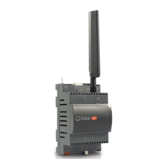
Carel CloudGate Assembly Procedure
Hide thumbs
Also See for CloudGate:
- Assembly instruction manual (12 pages) ,
- Assembly procedures (2 pages) ,
- Assembly procedure (2 pages)
Advertisement
Quick Links
"CloudGate" +0500150EZ - rel. 1.2 - 24.09.2021
CloudGate:
/
/ CONNECTOR'S DESCRIPTION
10
LAN
FIELD
9
12
3
2
1
/ key :
RC
说明
Description
[G(+), G0(-)] 24Vac/Vdc
1
Power supply connector [G(+), G0(-)] 24Vac/Vdc
2
LED
/ LED power-on (green)
3
Led/ Ethernet signal Led
IP / WPS /
2G/4G
4
Enable temporary IP / WPS / connection check to cloud (only for 2G/4G mod.)
USB
type A
5
USB standard HOST Port, type A connector, upgrading FW and log files downloading
RS485
/ RS485 serial opto-isolated; (
6
future use )
RS485
/ RS485 serial not opto-isolated ; (
7
Used for the connection to the network of RS485 devices )
FIELD
/ FIELD Ethernet ;
8
(
/ Used to access the internal configuration pages )
9
LAN
/ LAN Ethernet ;
10
/ Faston for shield ethernet port earth connection
11
/ 2G/4G Antenna connector (*)
2G/4G
12
Wi-Fi
/ Wi-Fi Antenna connector (*)
13
LED
/ LED synoptic
(*)
Wi-Fi 2G/4G
4G are available as an alternative to the other
LED
/ LEDS MEANINGS
/ Ethernet version
IP
RC
说明
Description
A
/ Cloud connection
B
IP
/ IP address assigned
C
/ Ethernet connection
D
Software engine: flashing: loading; steady: functioning
Wi-Fi 2G/4G
/ CloudGate Mobile (wi-fi or 2G/4G) vers.
E
RC
说明
Description
A
/ Cloud connection
B
IP
/ IP address assigned
C
/ Radio connection
D
Software engine: flashing: loading; steady: functioning
Led 2G/4G
Led Wi-Fi
E
Radio signal strength: green Led: 2G/4G; yellow Led: Wi-Fi
/ DIMENSIONS
IP
70
DIN
DIN 43880 IEC EN 50022
DIN mounting: fitted on DIN rail in accordance with DIN 43880 and IEC EN 50022;
Assembly procedure
6
2
7
8
11
13
5
4
"
•
"
/ R eserved for
RED:
- WIFI
- 2G/4G
FCC:
- WIFI+2G/4G:
ANATEL
/ The two options Wi-Fi and 2G /
A
B
C
D
24Vdc
RS485
A
B
C
D
RJ45
60
DIN
CloudGate
Wi-Fi 2G/4G
120Ω485
"
"
G G0 24 Vac +10%/-15% 50/60 Hz, 24 Vdc +5% /-5%
9W
-40~60 °C, 90% r.H
-40~70 °C, 90% r.H
1 RS485
- 1 RS485
"
"
BR2032 3 Vdc
EN 301 489-1
EN 301 489-17 Ver. 3.1.1 - EN 300 328 Ver. 2.1.1
EN 301 489-52 Ver. 1.1.0 - EN 301 511 Ver. 12.5.1 -
EN 301 908-1 Ver. 11.1.1
FCC 15
B
ICES003
FCC15.31 (k)
- ANSI C95.1. MPE - RSS-102. MPE
:
60950; 62368
4 DIN
= 70x110x60 mm
2
EN60950-1 / EN62368-1
IP10
G G0
5
2 24Vac 20 ......30VA
PGTA00TRX0 100/230Vac-
10W±2 1 DIN
-25°C
G
G0
注意
+
-
100 5e SFTP
RC
6.3
5VA
WARNING
This appliance must only be installed by service personnel with
suitable technical training and experience and who are aware
of the dangers they may be exposed to in the event of incorrect
configuration (qualified installers).
GENERAL NOTE
The Cloudgate family gateways have been designed to remotely
connect and monitor remotely HVAC/R units that are typically not
manned locally and not connected to the supervisory system in the
building where they are installed
Before performing any operations, check that the CloudGate contains:
1. the device itself;
2. for wireless version: an antenna ( Wi-Fi or 2G/4G type);
3. technical documents;
4. terminals kit and two resistors 120Ω for the end of the serial line.
Do not install products in environments with the following
characteristics:
•
relative humidity greater than the value specified in the technical
specifications;
•
strong vibrations or knocks;
•
exposure to aggressive and polluting atmospheres (e.g.: sulphur and
ammonia fumes, saline mist, smoke) so as to avoid corrosion and/or
oxidation;
•
strong magnetic and/or radio frequency interference (therefore avoid
installing the units near transmitting antennae);
•
exposure to direct sunlight and to the elements in general;
•
large and rapid fluctuations in the room temperature;
•
environments where explosives or mixes of flammable gases are present.
Installation warnings for Radio models
•
Before installing the product make sure the area is sufficiently
covered by a 2G/4G - Wi-Fi signal, if the model to be used includes
radio connectivity;
•
locate the antenna outside metal hardware.
TECHNICAL SPECIFICATIONS
Power supply
from G to G0: 24 Vac +10%/-15% 50/60 Hz, 24 Vdc +5%
/-5%
Input power
9W Max
Operating condit.
-40T60 °C, 90% U.R. non-condensing
Storage conditions -40T70 °C, 90% U.R. non-condensing
Serial Ports
1 RS485 Master opto-isolated- 1 RS485 Master non
opto-isolated
Battery (internal)
Lithium "button" type, BR2032, 3 Vdc, NOT rechargeable
Certification requirements
RED:
EN 301 489-1
EN 301 489-17 Ver. 3.1.1 - EN 300 328 Ver. 2.1.1
- WIFI
EN 301 489-52 Ver. 1.1.0 - EN 301 511 Ver. 12.5.1 -
- 2G/4G
EN 301 908-1 Ver. 11.1.1
FCC:
FCC Part 15 Subpart B, ICES003
FCC Part 15.31 (k) - ANSI C95.1. MPE - RSS-102. MPE
- WIFI+2G/4G
Safety:
60950; 62368
ANATEL
This equipment is not entitled to protection against
harmful interference and may not cause interference in
duly authorized systems.
Dimensions
4 DIN module = 70x110x60 mm
Pollution degree
2 according to EN60950-1 / EN62368-1
Index of protection IP10
Case material
tecnopolymer
Do not open the device when powered.
Power supply
•
Power supply to the product must only be connected between G
and G0
•
Maximum length =5 m.
•
If AC powered, use a dedicated safety transformer rated in Class 2
24Vac, 20...30VA,
protected against short-circuits and overload
secondary must be earthed connected
.
•
If direct current powered use PGTA00TRX0 power supply, 100/230Vac-
24Vdc (10W ±2% 1 DIN-module, Minimum Temperature = -25°C).
Connect the positive pole to G and negative pole to G0.
CAUTION: use separate cables for serial connections and power supply.
COMMUNICATION LINES
RS485 communication lines
The maximum length must not be over 1000m, via AWG24 shielded
cable for lines max 100m, AWG22 for lines max 500m, AWG20 for lines
max 1000m lenght, with screen connection to earth and not to GND.
The 120Ω terminal resistors, 1/4W into the first and the last devices of
the network, must be connected even if the lenght exceeds 100 meters.
The resistors, included in the product, are to be connected between the
serial + and - terminals:
•
observe the polarity (+.-,GND);
•
do not make branches in the line or star connections;
•
avoid laying the line near power cables.
To improve immunity of the controller to electromagnetic disturbance,
the serial connection cable must be twisted pair shielded, twisted two-
or three-wire depending on the insulation of the serial connection.
The following rule applies:
•
if the serial port is insulated (functionally) from the power supply, a
third wire is required in the serial cable to act as a common reference
for the controllers;
•
if the serial port is not optically-isolated and the common reference is
already present, the third wire is not needed.
RJ45 Ethernet Linee
Use shielded cables 100 m Cat.5e SFTP. To connect earth
the screen ethernet cable (functional connection), use a
female Faston 6,3mm, as indicated inthe figure.
The product is class II classified, but there is a faston for the earth
connection (functional) shiel cable. The connection could be directed
to earth (protection) or, earth (functional) separated by dangerous
voltages from to other external power supplies.
MOUNTING
To safeguard operators and the boards, disconnect power before
performing any operations. The product must be installed inside an
electrical panel; if it is made of plastic material use one with flammability
rating of 5VA.
,
without
Advertisement

Related Manuals for Carel CloudGate


Summary of Contents for Carel CloudGate
- Page 1 (qualified installers). GENERAL NOTE The Cloudgate family gateways have been designed to remotely connect and monitor remotely HVAC/R units that are typically not / CONNECTOR’S DESCRIPTION...
- Page 2 CloudGate has been paired to the router, the "obtain IP address" to malfunction of which CAREL can not be held responsible. The final client must use the product (B) LED will light up together with the radio signal intensity LED (E).
Need help?
Do you have a question about the CloudGate and is the answer not in the manual?
Questions and answers