Table of Contents
Advertisement
Quick Links
BENNETT 621 INTERCONNECTION BOX
(GENERIC CURRENT LOOP FUEL INTERFACE)
INCLUDES INSTRUCTIONS FOR THE INSTALLATION OF 1 TO 24 FUEL POSITIONS AND SERVICING THE 621
INTERCONNECTION BOX.
P/N 115763 115VAC Fuel Positions 1 through 24
P/N 104080 Fan Out Board
Only Trained Personnel May Work on This Equipment
READ THIS MANUAL
This manual has important information for safe installation and operation of this equipment. Read and understand this manual
before applying power. Keep this manual and tell all service personnel to read this manual. If you do not follow the instructions,
you can cause bodily injury, death, or damage to the equipment.
Installation & Service Manual
116186 Rev C 11/13/18
Bennett 1218 E. Pontaluna Road, Spring Lake, MI 49456
USA 800-235-7618 ~ Outside USA 231-798-1310
sales@bennettpump.com ~ www.bennettpump.com
Advertisement
Table of Contents

Related Manuals for Bennett 621


Summary of Contents for Bennett 621
- Page 1 BENNETT 621 INTERCONNECTION BOX (GENERIC CURRENT LOOP FUEL INTERFACE) INCLUDES INSTRUCTIONS FOR THE INSTALLATION OF 1 TO 24 FUEL POSITIONS AND SERVICING THE 621 INTERCONNECTION BOX. P/N 115763 115VAC Fuel Positions 1 through 24 P/N 104080 Fan Out Board Installation & Service Manual...
- Page 2 Examine the shipment immediately upon arrival to make certain there has been no damage or loss in transit. Bennett Pump Company, as shipper, is not liable for the hazards of transportation. Please make damage claims directly to the truck line.
-
Page 3: Table Of Contents
Hardware Connections ......................................... 3 Pump Controller Assembly 621 Box ..................................4 SECTION 3: INSTALLATION INSTRUCTIONS 621 Interconnection Box - Recommended Equipment and Materials ..................... 9 How To Mount the 621 Interconnection Box ..............................9 AC Power Requirements ......................................9 AC Power Wiring .......................................... 10 How to Connect Dispenser Fuel Communication Wires .......................... - Page 4 Bennett 621 Interconnection Box Instruction & Service Manual Table of Contents Page Intentionally Left Blank...
-
Page 5: Section 1: Safety Information
Note: Bennett Pump highly recommends all technicians observe HSSE FUEL ETHANOL IS POISONOUS AND SHOULD NOT BE INGESTED. policies defined by the supplier. Bennett Pump does not impose any DISCONNECT ALL POWER, RELIEVE PRESSURE TO THIS EQUIPMENT, restrictions or additional requirements contained in Environmental AND ASSOCIATED COMPRESSOR DURING INSTALLATION, SERVICE, OR Standards®... -
Page 6: General Information
Petroleum Institute Recommended Practice RP 2003, Protection Against Ignitions Arising out of Static, Lightening, and Stray Currents. Service of the Bennett products and all accessories (e.g. Nozzles, Hoses, and Breakaways) must be performed by a technician who is trained in accordance to all codes, standards, and regulations. -
Page 7: Section 2: Product Introduction
Product Introduction SECTION 2: PRODUCT INTRODUCTION The Bennett Model 621 Interconnection Box is an interface device for third party point-of-sale systems. It allows the customer to use Bennett Fuel Dispensing equipment with Consoles supporting the Generic Current Loop Fuel protocol. -
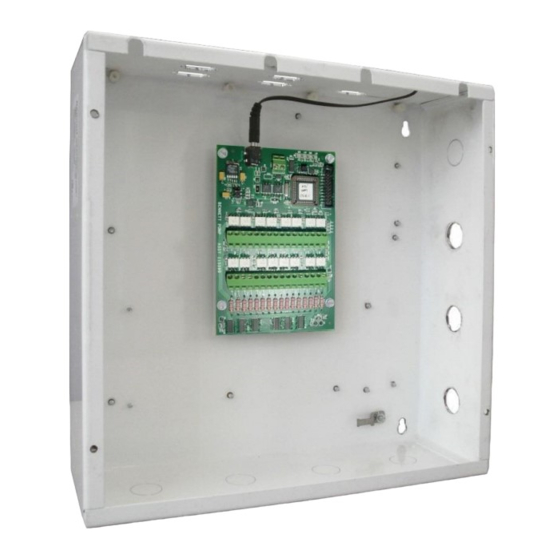
Page 8: Pump Controller Assembly 621 Box
Bennett 621 Interconnection Box Instruction & Service Manual Product Introduction PUMP CONTROLLER ASSE MBLY 621 BOX The 621 Interconnection Box is used to interface with third party point-of-sale systems and supports the Generic Current Loop Fuel protocol. ITEM DESCRIPTION Enclosure... - Page 9 GROUND SCREW AC LINE VOLTAGE INPUT The AC Power Module is used to provide AC power to the 621 board at the J1 connector. Only one dispenser electronics Hot and Neutral needs to be pulled per dispenser. Each 621 Interconnection Box uses one 120V, 50/60 Hz, or 240V, 50/60 Hz circuit for power. Make sure the power source has the correct frequency...
- Page 10 DISPENSER & POS COMMUNICATION The 621 Circuit Board has surface mount LEDs that are used for troubleshooting. If the console and dispensers are communicating, all LED’s will be flashing. If not communicating with the POS or Dispenser then the “Transmit” LED will be on constantly and the “Receive” LED will be off. Refer to the troubleshooting section for more information.
- Page 11 Bennett 621 Interconnection Box Instruction & Service Manual Product Introduction FAN-OUT CIRCUIT BOAR D The Fan-Out Circuit Board in the Bennett Interconnect Box provides a connection to the dispenser’s payment module. The Fan-Out Circuit Board has three sets of 10-position screw terminal strips. ...
- Page 12 Bennett 621 Interconnection Box Instruction & Service Manual Product Introduction CONNECTOR DESCRIPTIONS The following is a description of the connections and switches located on the Fan-Out Circuit board. RS485 COMMUNICATION – DATA (+) POSITIVE A 10-poition screw terminal strip provides a DATA (+) positive connection for each debit/credit terminal.
-
Page 13: Section 3: Installation Instructions
Voltmeter HOW TO MOUNT THE 621 INTERCONNECTION BOX The 621 Interconnection Box measures 12” x 12” x 4”. The enclosure requires four mounting screws. These four screws are on 10 ½” by 10 ½” centers. Note: When installing a 621 Interconnection Box pay attention to the locations of the AC Power Module port. -
Page 14: Ac Power Wiring
Fueling points 1 through 16 are labeld as 1 through 8. Fueling points 17 through 24 are labeld as 9-12. (e.g. Fueling point 1 & 2 are labeled as 1, fueling point 3 & 4 are labeled as 2 and etc. Refer to the 621 Wiring Diagram (P2915) for detailed information. -
Page 15: Connect Rs485 Communication Wires To Pos Interface
The following description is used for a RS485 payment communication. Field connections will depend on the Generic Current Loop Equipment Available at the Site. Please read and understand other manufacturer information prior to installation. Refer to the 621 Wiring Diagram (P2915) for detailed information. -
Page 16: Connection Diagram
Bennett 621 Interconnection Box Instruction & Service Manual Installation Instructions CONNECTION DIAGRAM... -
Page 17: Section 4: Service Instructions
LED DIAGNOSTICS The 621 Circuit Board has surface mount LEDs that are used for troubleshooting. If the console and dispensers are communicating, all LED’s will be flashing. If not communicating with the POS or Dispenser then the “Transmit” LED for that side will be on constantly and the “Receive”... -
Page 18: Helpful Programming Hints
NUCLEUS PROGRAMMING In order for the Bennett dispensers to function properly, the correct settings must be made in the pump-programming window of the Nucleus system. Three settings in the “Pump Options” window will need to be programmed correctly in order for the dispensers to function. -
Page 19: Section 5: Parts
PARTS LIST The parts listed in the table below are basic components needed for a new or existing 621 Interconnection Box. Some 621 Interconnection Boxes may require basic and/or additional materials such as bolts, fittings, etc. These items can be found in your local hardware store. - Page 20 Bennett 621 Interconnection Box Instruction & Service Manual Parts Page Intentionally Left Blank...
- Page 21 Bennett 621 Interconnection Box Instruction & Service Manual Bennett Limited Warranty...
- Page 22 Bennett 1218 E. Pontaluna Road, Spring Lake, MI 49456 USA 800-235-7618 ~ Outside USA 231-798-1310 sales@bennettpump.com ~ www.bennettpump.com...
Need help?
Do you have a question about the 621 and is the answer not in the manual?
Questions and answers