Advertisement
BOLT Control With Indication (BCI8000) Installation & Quick-start Instructions
For information on installing a complete BOLT Trim Tab System, please visit BennettTrimTabs.com/BOLT-Install
User Quick-start Guide
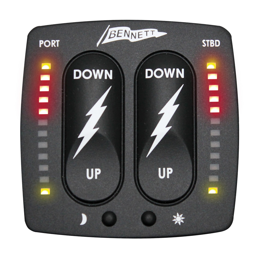
Lowers
Port Bow
BCI8700
Red LEDs indicate
the tab position.
All red LEDs
illuminated
indicate that the
tabs are fully
deployed (down)
Raises
Dims
Port Bow
LEDs
BCI Control Installation Instructions
• Before drilling any holes, read the entire instructions.
• Using the included template below, mark the
locations for the 3/16" holes and the 1"
center hole.
• Check carefully to ensure there are no obstructions behind
the console before drilling any holes.
• Using a 1" diameter hole-saw, drill the center hole.
Use a 3/16" drill for the four mounting stud holes.
• Place the helm display keypad onto the console, feeding the
pre-connected wires through the 1" center hole while
inserting the screws into each of the four holes.
• Once the control plate is properly seated, use the 4 white
nylon thumb nuts provided to secure the display.
• Connect the orange wire to the power source for the gauges
at the helm. This will power the control with all other dash
devices.
• Connect the purple wire to the ignition switch (or any 12V
circuit that turns ON and OFF with ignition) for auto tab
retraction. This wire is used to initiate Auto Tab Retraction
(ATR) when the ignition is switched to the OFF position. If
ATR is not desired, this connection may be omitted.
• BCI requires calibration. See reverse side.
Both templates on this page are identical. The second has been provided for dual station applications.
Both control templates below are identical. The second has been provided for dual station applications. Must be copied at 100% if replicated.
13
"
—
2
16
Verify template dimensions if
printed from the web or copied
Lowers
Starboard Bow
Red LEDs indicate
the tab position.
All red LEDs
illuminated
indicate that the
tabs are fully
deployed (down)
Brightens
Raises
LEDs
Starboard
Bow
BCI Control Installation Templates
BCI or BCN Control Templates
3
"
—
16
1
"
2
1
"
—
2
8
1
"
—
2
8
Diagnostics Relay Module Installation
BCI8500
• Mount the Diagnostics Relay Module under the helm using
the mounting hardware (2 screws provided) to secure it in
place.
• Plug the (2) 20 ft. wire harnesses (BAW20XX) into the port
and starboard actuators at one end. Then plug the other end
of the (2) 20 ft. wire harnesses (BAW20XX) to the port and
starboard plugs on the Diagnostics Relay Module (If cable
length is not long enough, an extension is available).
• Plug the 3 ft. wire harness on the display to the 3 ft. wire
harness on to the Diagnostics Relay Module (If cable length
is not long enough, an extension is available).
• Find a suitable dry location and mount using #8 x 1/2"
screws
• Connect helm control
• Plug the port yellow/blue 20ft. twisted cable (PN#
BAW20XX) to the port connector on the BRC Rocker
Control.
• Plug the starboard yellow/blue 20ft. twisted cable (PN#
BAW20XX) to the starboard connector on the BRC Rocker
Control. Connect ground (black wire) to ground bus
• Connect power (orange wire) to a supply capable of a 20A
(12V), or 10A (24V)
• Press any button on the control to power up (connect battery
or switch battery)
• See reverse side for system startup and wiring diagram
13
"
—
16
13
"
—
2
16
Verify template dimensions if
printed from the web or copied
Green Communications LED
Red Power LED
Starboard actuator up
(yellow), down (blue)
Port actuator up (yellow),
down (blue)
3
"
—
16
1
"
1
"
—
2
8
1
"
—
2
8
13
"
—
2
16
Advertisement
Table of Contents

Related Manuals for Bennett BOLT Control BCI8000


Summary of Contents for Bennett BOLT Control BCI8000
- Page 1 BOLT Control With Indication (BCI8000) Installation & Quick-start Instructions For information on installing a complete BOLT Trim Tab System, please visit BennettTrimTabs.com/BOLT-Install User Quick-start Guide Diagnostics Relay Module Installation Lowers Lowers Green Communications LED Port Bow Starboard Bow BCI8700 Red Power LED Starboard actuator up Red LEDs indicate Red LEDs indicate...
- Page 2 If either of the upper yellow LEDs is flashing, try to move the the relay module. Contact Bennett Marine Technical Support for actuator using the control to confirm that there is a problem.
Need help?
Do you have a question about the BOLT Control BCI8000 and is the answer not in the manual?
Questions and answers