Table of Contents
Advertisement
Quick Links
Advertisement
Table of Contents

Related Manuals for Keysight U9391C


Summary of Contents for Keysight U9391C
- Page 1 Keysight U9391C/F/G Comb Generator Operating and Service Manual...
- Page 2 Dec- set forth specifically in writing else- understood and met. laration of Conformity. where in the EULA. Keysight shall be under no obligation to update, revise or WARNING otherwise modify the Software. With respect to any technical data as defined by FAR 2.101, pursuant to FAR...
-
Page 3: Compliance Notices And Regulatory Information
This instrument complies with the outside of the home. WEEE Directive (2002/96/EC) marking requirement. This affixed MSIP-REM-Kst- product label indicates that you must xxxxxxxxxxxxxx not discard this electrical or electronic product in domestic household waste. Keysight U9391C/F/G Operating and Service Manual... -
Page 4: Waste Electrical And Electronic Equipment (Weee) Directive 2002/96/ Ec
To return this unwanted instrument, contact your nearest Keysight Service Center, or visit http://about.keysight.com/en/companyinfo/environment/takeback.shtml for more information. Sales and Technical Support To contact Keysight for sales and technical support, refer to the support links on the following Keysight websites: – www.keysight.com/find/mta (product-specific information and support, software and documentation updates) –... -
Page 5: Table Of Contents
......... .12 Key features of the U9391C/F/G Comb Generator . - Page 6 ......... . . 48 Keysight U9391C/F/G Operating and Service Manual...
- Page 7 ....30 Figure 3-2 1.85 mm, 2.4 mm, and 3.5 mm connector pin depths Figure 3-3 Dimensions of the U9391C comb generator ..34 Figure 3-4 Dimensions of the U9391F comb generator .
- Page 8 THIS PAGE HAS BEEN INTENTIONALLY LEFT BLANK. Keysight U9391C/F/G Operating and Service Manual...
- Page 9 U9391C/F/G environmental conditions ... .38 Table 4-1 Recommended test equipment for S-parameter test Table 4-2 Recommended test equipment for the NVNA test . . .42 Keysight U9391C/F/G Operating and Service Manual...
- Page 10 THIS PAGE HAS BEEN INTENTIONALLY LEFT BLANK. Keysight U9391C/F/G Operating and Service Manual...
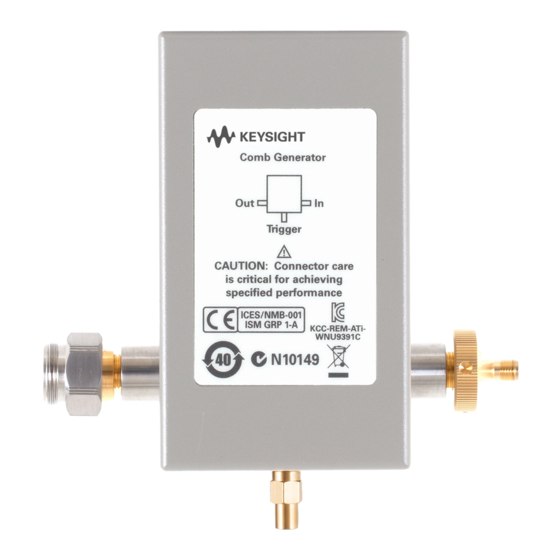
- Page 11 Keysight U9391C/F/G Comb Generator Operating and Service Manual Introduction Product Overview This chapter provides an overview of the Keysight U9391C/F/G Comb Generator.
-
Page 12: Introduction
Comb generators generate frequency harmonics at integer multiples of an RF input signal. Generally, comb generators available in the open market today are made with SRD diodes. The U9391C/F/G comb generator is based on the Keysight InP MMIC technology to ensure superior phase stability of the combs. - Page 13 This module has a trigger output which enables synchronization with the pulse’s repetition frequency. Calibration data stored inside the U9391C/F/G can be accessed directly by the PNA-X via the USB interface to be used in phase calibration.
-
Page 14: Key Features Of The U9391C/F/G Comb Generator
29 for more details). The network analyzer software automatically controls the U9391C/F/G via USB after it has been designated as a phase reference and/or calibration module. The phase calibration procedure is carried out by following the on-screen instructions on the PNA or PNA-X. -
Page 15: Options
Introduction Options There are two connector options available for the Keysight U9391C/F/G. Table 1-1 U9391C/F/G options Option U9391C U9391F U9391G 3.5 mm female 2.4 mm female 1.85 mm female Option FFF (output connector) (output connector) (output connector) 3.5 mm male 2.4 mm male... - Page 16 Introduction THIS PAGE HAS BEEN INTENTIONALLY LEFT BLANK. Keysight U9391C/F/G Operating and Service Manual...
- Page 17 Keysight U9391C/F/G Comb Generator Operating and Service Manual Installation Initial Inspection Service and Recertification Operating and Safety Precautions Applications This chapter provides you important information on how to check and prepare your instrument for operation.
-
Page 18: Installation
– Procedures for checking electrical performance are given under “Operator’s check” on page 40. 2 If the contents are damaged or defective, contact your nearest Keysight Technologies Service and Support Office. Refer to “Sales and Technical Support” on page 4 of this manual. Keysight Technologies will arrange for repair or replacement of the damaged or defective equipment. -
Page 19: Service And Recertification
Installation Service and Recertification If your comb generator modules require service or recertification, contact the nearest Keysight office for information on where to send it. Refer to “Sales and Technical Support” on page 4 of this manual. The performance of the comb generator modules can only be verified by specially manufactured equipment and calibration standards from Keysight. -
Page 20: Operating And Safety Precautions
– Wear a heel strap when working in an area with a conductive floor. – Ground yourself before you clean, inspect, or make a connection to the U9391C/F/G module. You can, for example, grasp the grounded outer shell of the analyzer test port or cable connector briefly. -
Page 21: Connector Care
– Gage connectors periodically. This not only provides assurance of proper mechanical tolerances, and thus connector performance, but can also indicate situations where the potential for damage to another connector may exist. The U9391C/F/G modules can be damaged if excessive torque is applied to CAUTION the connectors. -
Page 22: Applications
10MHz reference output and the input to comb generator. NVNA Two units of U9391C/F/G are required to carry out non-linear measurements. One unit is used as the phase reference module and the second unit as the phase calibration module. - Page 23 The phase calibration procedure is carried out by following the on-screen instructions on the PNA-X. After completing the calibration, the U9391C/F/G unit used for phase calibration can be disconnected. The other unit that is used as the phase reference will remain connected while the measurement is carried out.
- Page 24 (http://na.support.keysight.com/ pna/nvna/NVNAWebHelp/NVNAHelp.htm). For more information about NVNA application, please refer the publication document 5989-8575EN. When connecting the U9391C/F/G directly to the instrument test ports, the CAUTION modules will require mechanical support so as not to overstress the test port connectors.
-
Page 25: Smc+Phase
U9391C/F/G comb generator can be used. When using a comb generator, the calibration is done as a two-part process. In part one, a... - Page 26 DUT, receiver and transmitter hardware, calibration controller PC with Signal Optimizer, and all the necessary accessories such as cables and connectors including the U9391C/F/G comb generator. This helps engineers to set up and configure the DUT and test instruments easily and quickly for complicated 5G design verification test systems.
- Page 27 Keysight U9391C/F/G Comb Generator Operating and Service Manual Specifications General Specifications Mechanical Characteristics Environmental Conditions This chapter provides the specifications of the U9391C/F/G comb generator.
-
Page 28: Specifications General Specifications
1, 2, 4, 8, 16 1, 2, 4, 8, 16 Input return loss, S11 >10 dB (10 MHz to 6 GHz) >10 dB (10 MHz to 6 GHz) >10 dB (10 MHz to 6 GHz) Keysight U9391C/F/G Operating and Service Manual... -
Page 29: Physical Specifications
>5 dB (45 GHz to 67 GHz) [a] When driven by low phase noise sources, the U9391C/F/G will operate at frequencies lower than 10 MHz, but performance is not guaranteed. [b] For operations below 100 MHz, use a square wave to drive the U9391C/F/G. - Page 30 Specifications Current drawn will change when drive voltage changes. NOTE Figure 3-1 U9391-20013 DC bias cable Keysight U9391C/F/G Operating and Service Manual...
-
Page 31: Mechanical Characteristics
It reads as a negative value on the gage. The pin depth for a 1.85 mm, 2.4 mm, and 3.5 mm connector is shown in Figure 3-2 page The typical pin depths for the U9391C/F/G connectors are listed in “Typical pin depth values” on page 33. - Page 32 Specifications Female Male Outer conductor Center conductor Male pin depth Female pin depth Outer conductor Outer conductor mating plane mating plane Figure 3-2 1.85 mm, 2.4 mm, and 3.5 mm connector pin depths Keysight U9391C/F/G Operating and Service Manual...
-
Page 33: Typical Pin Depth Values
(0 to –50.0) (0 to –50.0) If the pin depth of a device does not measure within the observed pin depth limits, it may be an indication that the device fails to meet electrical specifications. Keysight U9391C/F/G Operating and Service Manual... -
Page 34: Mechanical Dimensions Of The U9391C/F/G
Specifications Mechanical dimensions of the U9391C/F/G Dimensions in millimeters (inches) Figure 3-3 Dimensions of the U9391C comb generator Keysight U9391C/F/G Operating and Service Manual... - Page 35 Specifications Dimensions in millimeters (inches) Figure 3-4 Dimensions of the U9391F comb generator Keysight U9391C/F/G Operating and Service Manual...
- Page 36 Specifications Dimensions in millimeters (inches) Figure 3-5 Dimensions of the U9391G comb generator The hand grip is designed for the U9391G only for better gripping and as a heat NOTE insulator for user's handling. Keysight U9391C/F/G Operating and Service Manual...
-
Page 37: Mechanical Dimensions For Squaring Circuit
Specifications Mechanical dimensions for squaring circuit Dimensions in millimeters (inches) Figure 3-6 Dimensions of the U9391-60009 squaring circuit Keysight U9391C/F/G Operating and Service Manual... -
Page 38: Environmental Conditions
5 to 500 Hz, 0.5 grms, 10 min/axis, four resonance search, 10 min dwell ESD immunity 8.0 kV per IEC 61000-4-2 – Direct discharge 15 kV per IEC 61000-4-2 – Air discharge [a] To outer conductor Keysight U9391C/F/G Operating and Service Manual... - Page 39 Keysight U9391C/F/G Comb Generator Operating and Service Manual Operating Guide Operating Instructions Service Instructions This chapter provides simple quick-check instructions to verify the U9391C/F/G comb generator’s functionality prior to usage. It also provides information on service and maintenance of the U9391C/F/G.
-
Page 40: Operating Guide
– Current: 2 x 0.85 A [a] N5242A, N5244A, N5245A, and N5247A [b] 26.5 GHz for the U9391C, 50 GHz for the U9391F, and 67 GHz for the U9391G [c] To power up two units of the U9391C/U9391F [d] To power up two units of the U9391G [e] Current drawn by the device under normal operating condition after start up. -
Page 41: Table
1 Click on the PNA-X application. Calibrate the network analyzer with full 2-port calibration using the appropriate electronic or mechanical calibration kit. 2 Connect the Input of the U9391C/F/G to Port 1 of the network analyzer and the Output of the U9391C/F/G to Port 2 of the network analyzer. -
Page 42: Recommended Test Equipment For The Nvna Test
Not applicable [a] N5242A, N5244A, N5245A, and N5247A [b] 2650 for the U9391C, and 5000 for the U9391F, and 6700 for the U9391G [c] To power up two units of the U9391C/U9391F [d] To power up two units of the U9391G... - Page 43 3 Shut down the network analyzer application and turn on the NVNA application. Leaving the network analyzer application running in the background will cause the NVNA applications to not function properly. 4 Click Response and select Couple Segment from the Keysight NVNA’s main menu as shown in Figure 4-3.
- Page 44 Maximum harmonics: 2650/5000/6700 d IFBW: 10 Hz Figure 4-3 NVNA’s main menu 7 Click Response and select Calibration to start the NVNA Cal Wizard. [1] 2650 for the U9391C, 5000 for U9391F, and 6700 for U9391G Keysight U9391C/F/G Operating and Service Manual...
- Page 45 10 Select Port 1 or Port 3 and follow the instructions to perform the Amplitude Calibration using the power sensor, before performing the Phase Calibration. 11 To perform Phase Calibration, select the phase reference unit that is identified to use for calibration. Then click Next. Keysight U9391C/F/G Operating and Service Manual...
- Page 46 Format: Select Log Mag (to measure comb amplitude) or Phase (to measure comb phase) b Domain: Select Frequency Click Apply to apply the measurement settings before selecting the measurement mode (single or continuous). c Measure: Select Single or Continuous Keysight U9391C/F/G Operating and Service Manual...
- Page 47 Operating Guide Figure 4-6 NVNA’s main menu 14 Compare the measurement results with the specifications in Table 3-1 page 15 The phase measurement will fluctuate between +180 to –180 due to phase ° wrapping. Keysight U9391C/F/G Operating and Service Manual...
-
Page 48: Service Instructions
Operating Guide Service Instructions Adjustment The U9391C/F/G comb generator does not have internal adjustments and should not be opened. Repair If your U9391C/F/G comb generator requires repair services, contact your nearest Keysight Sales and Service Center. Maintenance The connectors, particularly the connector faces, must be kept clean. For instruction on connecting and care of your connectors, refer to the Microwave Connector Care Quick Reference Card (08510-90360). - Page 49 This information is subject to change without notice. Always refer to the English version at the Keysight website for the latest revision. © Keysight Technologies 2008 - 2017 Edition 8, July 2017 Printed in Malaysia *U9391-90001* U9391-90001 www.keysight.com...
Need help?
Do you have a question about the U9391C and is the answer not in the manual?
Questions and answers